The USB interface began to be widely used about 20 years ago, to be precise, since the spring of 1997. It was then that the universal serial bus was implemented in hardware in many personal computer motherboards. Currently, this type of connecting peripherals to a PC is a standard, versions have been released that have significantly increased the data exchange speed, and new types of connectors have appeared. Let's try to understand the specifications, pinouts and other features of USB.
What are the advantages of Universal Serial Bus?
The introduction of this connection method made it possible:
- Quickly connect various peripheral devices to your PC, from the keyboard to external disk drives.
- Make full use of Plug&Play technology, which simplifies the connection and configuration of peripherals.
- Refusal of a number of outdated interfaces, which had a positive impact on the functionality of computing systems.
- The bus allows not only to transfer data, but also to supply power to connected devices, with a load current limit of 0.5 and 0.9 A for the old and new generations. This made it possible to use USB to charge phones, as well as connect various gadgets (mini fans, lights, etc.).
- It has become possible to manufacture mobile controllers, for example, a USB RJ-45 network card, electronic keys for entering and exiting the system
Types of USB connectors - main differences and features
There are three specifications (versions) of this type of connection that are partially compatible with each other:
- The very first version that has become widespread is v 1. It is an improved modification of the previous version (1.0), which practically did not leave the prototype phase due to serious errors in the data transfer protocol. This specification has the following characteristics:
- Dual-mode data transfer at high and low speed (12.0 and 1.50 Mbps, respectively).
- Possibility of connecting more than a hundred different devices (including hubs).
- The maximum cord length is 3.0 and 5.0 m for high and low transfer speeds, respectively.
- The rated bus voltage is 5.0 V, the permissible load current of the connected equipment is 0.5 A.
Today this standard is practically not used due to its low throughput.
- The dominant second specification today... This standard is fully compatible with the previous modification. A distinctive feature is the presence of a high-speed data exchange protocol (up to 480.0 Mbit per second).
Due to full hardware compatibility with the younger version, peripheral devices of this standard can be connected to the previous modification. True, the throughput will decrease up to 35-40 times, and in some cases more.
Since these versions are fully compatible, their cables and connectors are identical.
Please note that, despite the bandwidth specified in the specification, the actual data exchange speed in the second generation is somewhat lower (about 30-35 MB per second). This is due to the implementation of the protocol, which leads to delays between data packets. Since modern drives have a read speed four times higher than the throughput of the second modification, that is, it does not meet current requirements.
- The 3rd generation universal bus was developed specifically to solve problems of insufficient bandwidth. According to the specification, this modification is capable of exchanging information at a speed of 5.0 Gbit per second, which is almost three times the reading speed of modern drives. Plugs and sockets of the latest modification are usually marked blue to facilitate identification of belonging to this specification.

Another feature of the third generation is an increase in the rated current to 0.9 A, which allows you to power a number of devices and eliminate the need for separate power supplies for them.
As for compatibility with the previous version, it is partially implemented; this will be discussed in detail below.
Classification and pinout
Connectors are usually classified by type, there are only two of them:

Note that such convectors are compatible only between earlier modifications.

In addition, there are extension cables for the ports of this interface. At one end there is a type A plug, and at the other there is a socket for it, that is, in fact, a “female” - “male” connection. Such cords can be very useful, for example, to connect a flash drive without crawling under the table to the system unit.

Now let's look at how contacts are wired for each of the types listed above.
USB 2.0 connector pinout (types A and B)
Since the physical plugs and sockets of early versions 1.1 and 2.0 do not differ from each other, we will present the wiring of the latter.
 Figure 6. Wiring the plug and socket of type A connector
 Designation:
- A – nest.
- B – plug.
- 1 – power supply +5.0 V.
- 2 and 3 signal wires.
- 4 – mass.
In the figure, the coloring of the contacts is shown according to the colors of the wire, and corresponds to the accepted specification.
Now let's look at the wiring of the classic socket B.

Designation:
- A – plug connected to the socket on peripheral devices.
- B – socket on a peripheral device.
- 1 – power contact (+5 V).
- 2 and 3 – signal contacts.
- 4 – ground wire contact.
The colors of the contacts correspond to the accepted colors of the wires in the cord.
USB 3.0 pinout (types A and B)
In the third generation, peripheral devices are connected via 10 (9 if there is no shielding braid) wires; accordingly, the number of contacts is also increased. But they are located in such a way that it is possible to connect devices of earlier generations. That is, the +5.0 V contacts, GND, D+ and D-, are located in the same way as in the previous version. The wiring for Type A socket is shown in the figure below.
 Figure 8. Pinout of Type A connector in USB 3.0
 Designation:
- A – plug.
- B – nest.
- 1, 2, 3, 4 – connectors fully correspond to the pinout of the plug for version 2.0 (see B in Fig. 6), the colors of the wires also match.
- 5 (SS_TX-) and 6 (SS_TX+) connectors for data transmission wires via the SUPER_SPEED protocol.
- 7 – ground (GND) for signal wires.
- 8 (SS_RX-) and 9 (SS_RX+) connectors for data receiving wires using the SUPER_SPEED protocol.
The colors in the figure correspond to those generally accepted for this standard.
As mentioned above, a plug from an earlier model can be inserted into the socket of this port; accordingly, the throughput will decrease. As for the plug of the third generation of the universal bus, it is impossible to insert it into the sockets of the early release.
Now let's look at the pinout for the type B socket. Unlike the previous type, such a socket is incompatible with any plug of earlier versions.

Designations:
A and B are plug and socket, respectively.
Digital signatures for contacts correspond to the description in Figure 8.
The color is as close as possible to the color markings of the wires in the cord.
Micro USB connector pinout
To begin with, we present the wiring for this specification.

As can be seen from the figure, this is a 5 pin connection; both the plug (A) and socket (B) have four contacts. Their purpose and digital and color designation correspond to the accepted standard, which was given above.
Description of the micro USB connector for version 3.0.
For this connection, a characteristically shaped 10 pin connector is used. In fact, it consists of two parts of 5 pins each, and one of them fully corresponds to the previous version of the interface. This implementation is somewhat confusing, especially considering the incompatibility of these types. Probably, the developers planned to make it possible to work with connectors of earlier modifications, but subsequently abandoned this idea or have not yet implemented it.

The figure shows the pinout of the plug (A) and the appearance of the micro USB socket (B).
Contacts 1 to 5 fully correspond to the second generation micro connector, the purpose of the other contacts is as follows:
- 6 and 7 – data transmission via high-speed protocol (SS_TX- and SS_TX+, respectively).
- 8 – mass for high-speed information channels.
- 9 and 10 – data reception via high-speed protocol (SS_RX- and SS_RX+, respectively).
Mini USB pinout
This connection option is used only in early versions of the interface; in the third generation this type is not used.

As you can see, the wiring of the plug and socket is almost identical to the micro USB, respectively, the color scheme of the wires and the contact numbers are also the same. Actually, the differences are only in shape and size.
In this article we have presented only standard types of connections; many manufacturers of digital equipment practice introducing their own standards; there you can find connectors for 7 pin, 8 pin, etc. This introduces certain difficulties, especially when the question arises of finding a charger for a mobile phone. It should also be noted that manufacturers of such “exclusive” products are in no hurry to tell how the USB pinout is done in such contactors. But, as a rule, this information is easy to find on thematic forums.
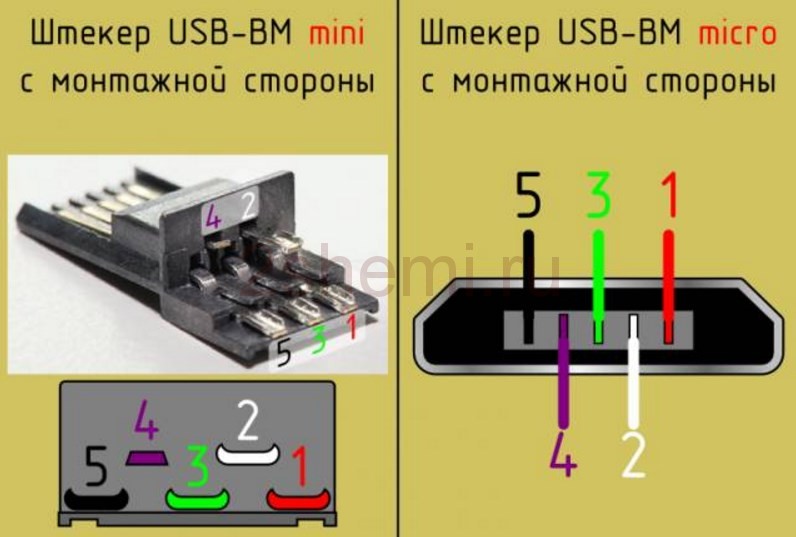
Correct pinout of the plug and socket of the Micro-USB connector for connecting power and charging a mobile phone or tablet.
Pinout diagram

Assignment of micro-USB connector contacts - socket and plug
The USB (Universal Serial Bus) connector is a universal-purpose serial bus, the most common wired method of connecting external devices to a computer. This connector allows you to organize data exchange between a computer and a video camera, card reader, MP3 player, external hard drive, or smartphone.
Charging the battery via Micro USB
In addition, it supplies a 5-volt power supply to charge the battery of wearable gadgets. Since almost all modern lithium batteries have an operating voltage of 3.7 V, the 5 V supplied via Micro-USB is excellent for replenishing energy. True, not directly to the battery, but through the charger converter.
I’m glad that the connector pinout is the same for all smartphone manufacturers - Samsung, LG, Huaway and others. Thus, a 220 V charger-adapter from one phone is most often suitable for charging another without changing the pinout.
- The main advantage of the Micro-USB connector over other types is the ability to connect Plug&Play devices without the need to restart the computer or manually install drivers. Devices can be connected while the computer is running and disconnected without having to press any buttons.
Difference between Micro-USB A and B
Please note: The micro connector contains 5 pins. Type B connectors do not use the fourth pin. In type “A” connectors, the fourth contact is connected to GND (minus). And for GND - the fifth contact.

The USB (Universal Serial Bus) interface has been in active use for 2 decades, and during this time several standards have been created. This first happened in 1997, when a corresponding connector appeared on motherboards. Today we will talk about USB standards and pinouts, but first you need to highlight the benefits tires.
One of the main ones is Plug & Play support. Now, after connecting the device, you no longer need to manually install the necessary drivers and restart the personal computer.
The bus not only allows information to be transferred, but also provides power to the connected device. As a result Have an opportunity create mobile network and sound cards, as well as other types of controllers.
USB versions
Currently created 3 standards this interface. The main differences between them are not the pinout of the USB connector, but the speed of information exchange. At the same time, compatibility of new versions with previous ones is ensured, which makes life much easier for users.
Type 1.1
This standard is capable of providing transmission speed information up to 12 Mb/s. At the time of its creation, this was a good indicator, but there was still a faster interface - IEEE 1394 or FireWire (up to 400 Mb/s), developed by Apple. However, USB 1.1 became quite widespread and was used for several years.
Among the main characteristics of this specification it should be noted:
- Possibility of connecting more than 100 devices, including hubs.
- Maximum cord length 3 m.
- The bus voltage is 5 V and the load current is 0.5 A.
Type 2.0

It should be taken into account that the actual throughput of USB 2.0 differed significantly from that specified in the specification. This is due to the implementation of a protocol that allows delays in the transmission of data packets. In recent years, a lot of devices have appeared, the normal operation of which required a large throughput tire.
Type 3.0
 This is a new standard, the mass distribution of which began in 2010. It allows you to transfer information at speeds of up to 5 Gb/s. Although the pinout of the USB connector 3.0 has some differences from the 2nd version, they are fully compatible. To distinguish the connectors of these standards, USB 3.0 sockets and plugs are marked in blue.
There are also certain inconsistencies in the wiring of connectors. The rated current has been increased to 0.9 A. As a result, the number of peripheral devices has increased, the operation of which no longer requires a separate power source. They have their own classification and USB connectors:
- Type A is designed to connect to a socket installed on the computer motherboard or hub.
- Type B is used in peripheral devices (printers).
Connectors of the second type are quite large and cannot be installed on portable gadgets. To correct the situation, micro- and mini USB standards were created.
Pinout of USB 2.0 connectors (types A and B)
Since the connectors of the first versions of the universal serial bus are not physically different, it is enough to know the wiring of the latest standard. The first contact is supplied with 5 V power, and the 2nd and 3rd wires are used to transmit the signal. The USB cable pinout by color is as follows:
- 1 - red.
- 2 - white.
- 3 - green.
- 4 - black.
USB 3.0 connector pinout
In the latest version of the standard, instead of 4 contacts, 9 are used. The color scheme of the wiring is shown in the figure and looks like this:
- The assignment of pins 1 to 4 is similar to the previous version.
- Wires 5−6 and 8−9 are used respectively for transmitting/receiving data via the Super Speed protocol.
- 7 - mass of signal wires.
Type B connectors version 3.0 are not compatible with previous standards.
The pinout of mini-USB is similar to micro, but in the third version of the interface only the latter type of connector is used. Micro-USB 2.0 has 5 contacts, however, only 4 are used. In the latest version, the number of wires has been doubled. Contacts 1-5 perform the same functions as in the connectors of the previous standard, and the rest are designed to solve the following tasks:
- 6−7 and 9−10 - respectively for transmitting/receiving data via a high-speed protocol.
- 8 - ground of information wires.
Micro USB pinout for charging
Although all mobile gadgets charge via USB, there is no single standard, and each manufacturer has developed its own scheme. You can use any power adapter to recharge the battery. For example, in an iPhone, for this you need to connect pins 2, 3 to 4 using a resistor with a nominal resistance of 50 kOhm, and from 5 to 75 kOhm. The main competitor Samsung Galaxy has a simpler pinout of the micro-USB charging connector. You will need to place a jumper between pins 2 and 3, and connect 4 to 5 with a 200 kOhm resistor.
Alternative connection methods, such as USB connectors, are widely used to connect modern devices.
This name is quite common and is translated from English as “universal serial bus”.
All USB connectors are available in three versions.
Characteristic features of the main three versions of USB connectors
The first version of USB connectors (1.1). Its characteristic feature is a very low speed, at which all information is transmitted with a long delay.
The transfer speed is 12 Mbit/s. Its main purpose is to be used for interconnecting devices.
Second version of USB connectors (2.0).
Characterized by a data transfer rate of 480 Mbit/s. This corresponds to a speed of 48 MB/s.
The bulk of all modern technical instruments and devices are adapted to use this particular version. It is the most popular and well-known, and therefore is in demand in the electrical goods market.
True, due to many factors, the real speed of this standard does not exceed 30 - 33 MB/s.
Since the latest releases of hard drives, for example, SSDs, are designed to read information at a much higher speed (almost 4 times), this version of the standard delays the effect of new drive models.
This shows the main drawback of the properties of USB 2.0 connectors. But despite this, certain devices are quite compatible with this version of connectors: mice, keyboards, scanners and printers.
Third version of USB (3.0).
This version is characterized by the speed of information transfer - 5 Gbit/s – which is considered a fairly high figure.
This speed corresponds 500 MB/s
This is much higher than the speed of the latest generation hard drives (150 - 170 MB/s).
USB 3.0 connectors are specially marked blue for recognition.

Interface compatibility
If we consider the issue of compatibility of devices that have the connectors presented above, we can state that the first and second versions of USB connectors can be interchangeable with each other.
A particular device that has a USB version 2 connection but accepts a version 1 connection may display a message indicating its ability to perform faster.

Because this computer model is designed to receive information through the second version, the speed of which is higher than the first.
That is, the full speed potential of this device will not be used.
Modern devices that have connectors of the second version can be connected to the third version of USB, and the use of the third version relative to the second is excluded, except for USB 3.0 type A.

Additional contacts create conditions for increasing the speed of the interface - this is a feature of the latest models of cables and devices that have connectors of the third version of USB.
USB power supply
The power for which connected devices with USB connectors are designed is 2,5 W and also 4,5 W (for the third version).
Based on this, USB connectors of all versions require voltage 5 V. Current up to 0,5 Oh, and for the third version - 0.9 A.
USB 3.0 pins.

Devices such as players, memory cards, phones, flash drives (that is, devices with low power) can be freely connected using such connectors.
And technical means with high power are connected to an external electrical network.
Connector types
The second and third versions of connectors are distinguished by size: Mini USB (small sizes), Micro USB (even smaller sizes); and also by types: A, B.

USB 2.0 type A connector.

A reliable connector whose main characteristic is the ability to withstand more than one connection without losing its integrity.
The cross-section of the connector has a rectangular shape, which creates additional protection when connecting.

Its disadvantage is its large size, and all modern devices are portable, which influenced the development and production of connectors of a similar type, but of a smaller size.
USB 2.0 Type A was introduced in the nineties and is currently still the most used.
A significant number of low-power devices have it: keyboard, mouse, flash drive and others.
USB connector version 2.0 type B.

We mainly find its application in stationary devices of large dimensions. These include scanners, printers, and less commonly ADSL modems.
It is rare, but it still happens that cables of this type are sold separately from the equipment itself, because they are not part of the technical device kit. Therefore, check the complete set of devices.

Connectors of this type are not as popular as type A connectors.
The square and trapezoidal shape is inherent in all type B connectors.
These include both Mini and Micro.
The peculiarity of the cross-section of type “B” connectors is their square shape, which distinguishes it from other types.
Mini USB connectors of the second version, type B.
The name of this type of connector indicates that it has very small dimensions. And this is not surprising, because the modern market increasingly offers miniature goods.
Thanks to the use of personal hard drives, card readers, players and other small devices, USB Mini connectors related to type B have become very popular.

It should be noted that such connectors are unreliable. It becomes loose with frequent use.
But the use of USB Mini Type A connector models is extremely limited.
Micro USB 2.0 type B connectors.
Micro USB connector models are more advanced than Mini USB models.
This type of connector is incredibly small in size.
Unlike the previous mini types presented, these connectors are very reliable with their fastenings and connection fixation.

The Micro USB 2.0 connector type “B” has been recognized in its qualities as uniform for universal use for charging all portable devices.
What will happen over time, when all manufacturers begin to produce equipment adapted specifically to such connectors. It probably won't take long to see it.
But this decision was already made in 2011 by all modern manufacturers, although the Micro USB 2.0 type “B” connector is not yet present on all devices.
USB third version type A connectors.
USB 3.0 connectors have greater speed for information transfer due to additional contacts.
With such changes, feedback compatibility is still maintained. Its use has been established in computers and laptops of the latest generation.

USB connectors third version type B.
The third version of USB type “B” connectors are not suitable for connecting USB connectors of the second version.
It is used in the operation of peripheral devices with medium and large productivity.

Micro USB 3.0.
Modern high-speed external drives, as well as SSD-type drives, are basically all equipped with a connector that is characterized by a high speed of information exchange.

It is increasingly occupying a leading position due to the fact that it has very high-quality connections.
The connector is easy to use due to its compact size. Its predecessor is considered to be a Micro USB connector.

Connector pinoutUSB.

The main differences between Micro and Mini USB connectors
At first glance, these connectors are very similar. Indeed, most of the characteristic features of the basic parameters of these species coincide.
But upon closer inspection, you can notice the following differences:
- The USB Mini connector is larger than the USB Micro connector.
- The presence of special-purpose latches on the back side of the USB Micro connectors.

Many users have already become convinced that it is most convenient to have not just one type of connector, but several, because different types of devices have different types of USB connectors.
Unfortunately, device manufacturers have not yet come to a single standard, and most likely will not come for a long time, because each type of USB connector has its own purpose.
Most modern mobile phones, smartphones, tablets and other wearable gadgets support charging via a mini-USB or micro-USB USB socket. True, a single standard is still far away and each company is trying to do the pinout in its own way. Probably they should buy the charger from her. It’s good that the USB plug and socket itself were made standard, as well as the supply voltage of 5 volts. So, having any charger adapter, you can theoretically charge any smartphone. How? and read on.

Pinout of USB connectors for Nokia, Philips, LG, Samsung, HTC
Brands Nokia, Philips, LG, Samsung, HTC and many other phones will recognize the charger only if the Data+ and Data- pins (2nd and 3rd) are shorted. You can short them in the USB_AF socket of the charger and easily charge your phone via a standard data cable.

Pinout of USB connectors on the plug
If the charger already has an output cord (instead of an output jack), and you need to solder a mini-USB or micro-USB plug to it, then you do not need to connect pins 2 and 3 in the mini/micro USB itself. In this case, you solder the plus to 1 contact, and the minus to the 5th (last).

Pinout of USB connectors for iPhone
For iPhones, the Data+ (2) and Data- (3) contacts should be connected to the GND (4) contact through 50 kOhm resistors, and to the +5V contact through 75 kOhm resistors.

Samsung Galaxy charging connector pinout
To charge the Samsung Galaxy, a 200 kOhm resistor must be installed in the USB micro-BM plug between pins 4 and 5 and a jumper between pins 2 and 3.

Pinout of USB connectors for Garmin navigator
A special data cable is required to power or charge your Garmin navigator. Just to power the navigator via cable, you need to short-circuit pins 4 and 5 of the mini-USB plug. To recharge, you need to connect pins 4 and 5 through an 18 kOhm resistor.

Pinout diagrams for charging tablets
Almost any tablet computer requires a large current to charge - 2 times more than a smartphone, and charging through the mini/micro-USB socket in many tablets is simply not provided by the manufacturer. After all, even USB 3.0 will not provide more than 0.9 amperes. Therefore, a separate nest (often round type) is placed. But it can also be adapted to a powerful USB power source if you solder an adapter like this.

Pinout of the charging socket of the Samsung Galaxy Tab tablet
To properly charge the Samsung Galaxy Tab tablet, they recommend another circuit: two resistors: 33 kOhm between +5 and jumper D-D+; 10 kOhm between GND and jumper D-D+.

Pinout of charging port connectors
Here are several diagrams of the voltages on the USB contacts, indicating the values of the resistors that allow these voltages to be obtained. Where a resistance of 200 Ohms is indicated, you need to install a jumper whose resistance should not exceed this value.
Charger port classification
- SDP(Standard Downstream Ports) – data exchange and charging, allows current up to 0.5 A.
- CDP(Charging Downstream Ports) – data exchange and charging, allows current up to 1.5 A; hardware identification of the port type (enumeration) is performed before the gadget connects the data lines (D- and D+) to its USB transceiver.
- DCP(Dedicated Charging Ports) - charging only, allows current up to 1.5 A.
- ACA(Accessory Charger Adapter) - PD-OTG operation is declared in Host mode (with connection to PD peripherals - USB-Hub, mouse, keyboard, HDD and with the possibility of additional power supply), for some devices - with the ability to charge PD during an OTG session .
How to remake a plug with your own hands
 Now you have a pinout diagram for all popular smartphones and tablets, so if you have the skill to work with a soldering iron, there will be no problems converting any standard USB connector to the type your device needs. Any standard charging that is based on the use of USB involves the use of only two wires - +5V and a common (negative) contact.
Just take any 220V/5V charging adapter and cut off the USB connector from it. The cut end is completely freed from the shield while the remaining four wires are stripped and tinned. Now we take a cable with a USB connector of the desired type, after which we also cut off the excess from it and carry out the same procedure. Now all that remains is to simply solder the wires together according to the diagram, after which each connection is insulated separately. The resulting case is wrapped on top with electrical tape or tape. You can fill it with hot glue - also a normal option.
Bonus: all other connectors (sockets) for mobile phones and their pinouts are available in a single large table -.


