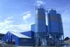
Oil transformers of the TM-250 series as well as transformers TMZ-250 are designed for operation in electrical networks with a voltage of 6 or 10 kV to 35 kV in open electrical installations in temperate climates (version U1 according to GOST 15150-69) and are used to reduce the high voltage of the supply network to the established level consumption. The transformer is placed in a tank with oil to cool and prevent destruction of the transformer windings from the external environment.
Main operational characteristics of TM-250
The guaranteed service life of the TM-250 transformer is 3 years from the date of commissioning of the transformer.
The established mean time between failures is at least 250,000 hours.
The full service life of TM-250 is at least 30 years.
Mains frequency – 50Hz.
Voltage on the HV side – 6; 6.3; 10; 10.5; 27.5; 35 kV.
Voltage on the LV side – 0.4; 0.23 and 0.69 kV.
At your request, we can produce TM-250 transformers on the HV and LV side with other voltage values, as well as non-standard transformers
Symbol of transformers TM-250
Composition and design of the TM-250 transformer.
The TM-250 transformer consists of: a tank with radiators, a tank cover, an expansion tank and an active part.
The tank is equipped with a plug for taking an oil sample and a plate for grounding the transformer. The outer surface of the tank is painted with weather-resistant gray, light gray or dark gray paints (the color tone may vary). All transformer seals are made of oil-resistant rubber.
The transformer tank consists of:
- walls made of steel sheet with a thickness of 2.5 mm to 4 mm. (depending on the power of the transformer);
- top frame;
- radiators;
- loops for lifting the transformer
- bottom with support legs (channels).
The following are installed on the cover of transformers TM and TMG:
- HV and LV inputs
- switch drive;
- loops for lifting the transformer
- safety valve (on transformers type TMG and TMGF),
- membrane safety device
- pressure-vacuum gauge
The expansion tank is used to compensate for changes in oil volume depending on external factors. The tank is equipped with:
- Min and max oil level marks in the transformer
- oil filler neck
Instrumentation and signaling equipment for transformer TM-250.
The oil level in transformers is monitored visually using the oil level indicator, which is located:
- on the wall of the oil conservator for transformers of the TM and TMF types;
- on the tank wall of the TMG and TMGF transformers.
If there is a thermal unit, the temperature of the upper layers of oil in the transformer tank is additionally monitored using an alcohol thermometer.
Technical characteristics of TMG-250 transformers
|
Transformer type |
Voltage class, |
Power, kVA |
Short-circuit voltage at 75ºС |
Losses, W |
Overall dimensions, mm |
Weight oil, kg |
General weight, kg. |
|||||
|
short circuit at 75ºС |
||||||||||||
| 6;10 | 4,5 | 740 | 800 | |||||||||
| TM-250 | 35 | 250 | 6,5 | 770 | 4200 | 1450 | 950 | 1880 | 660 | 660 | 500 | 1550 |
If you want to manufacture a transformer according to your technical requirements, you need to fill out a questionnaire for TM-250, which you can find on our website.
Purpose and scope of transformers type TM
Three-phase transformers with natural oil cooling, designed for converting electrical energy in power supply networks, as well as for powering various consumers in networks alternating current frequency 50 Hz.
The transformers provide the ability to regulate voltage: 5 steps with a regulation range of ±2×2.5% of the nominal. Type of regulation - PSW (switching without excitation). The transformer is switched to another control stage manually in the off state.
Design of transformers type TM
Transformers consist of an active part, a cover and an oval-shaped welded tank. On the cover there are HV and LV inputs, a switch drive, a conservator with an oil indicator and an air dryer.
The active part consists of a magnetic core with windings, lower and upper yoke beams, and a winding tap switch. The magnetic system of the transformer is flat-laminated, rod type, assembled from cold-rolled electrical steel.
The design of the transformer windings is cylindrical. HV windings have adjustable taps. In the manufacture of windings, block winding is used (i.e., the HV winding is wound onto the LV winding).
The active part of the transformer is rigidly fixed in the upper part of the tank in four places with spacer screws. A switch is installed above the active part, to the fixed contacts of which the adjusting taps of the HV windings are connected.
Hooks for lifting the transformer are welded at the top of the tank. There is a ground plate and oil drain plug at the bottom of the tank. The design of the plug allows you to take an oil sample by partially unscrewing it. Strips with holes for attaching the transformer to the foundation are welded to the bottom of the tank.
Types of transformers TM
Transformer TM-6300. Unique power oil transformers, type TM, power 6300 kVA, voltage class 6 (10) kV. Type of regulation - off-circuit switching (switching without excitation) ±2×2.5%
Transformer TM-4000. Unique power oil transformers, type TM, power 4000 kVA, voltage class 6 (10) kV. Type of regulation - off-circuit switching (switching without excitation) ±2×2.5%
Transformer TM-2500. Unique power oil transformers, type TM, power 2500 kVA, voltage class 6 (10) kV. Type of regulation - off-circuit switching (switching without excitation) ±2×2.5%
Transformer TM-1600/ 6. Power oil transformers, type TM, power 1600 kVA, voltage class 6 kV. Type of regulation - off-circuit switching (switching without excitation) ±2×2.5%
Transformer TM-1600/10. Power oil transformers, type TM, power 1600 kVA, voltage class 10 kV. Type of regulation - off-circuit switching (switching without excitation) ±2×2.5%
Transformer TM-1000/10. Power oil transformers, type TM, power 1000 kVA, voltage class 10 kV. Type of regulation - off-circuit switching (switching without excitation) ±2×2.5%
Transformer TM-1000/6. Power oil transformers, type TM, power 1000 kVA, voltage class 6 kV. Type of regulation - off-circuit switching (switching without excitation) ±2×2.5%
Transformer TM-630/ 6. Power oil transformers, type TM, power 630 kVA, voltage class 6 kV. Type of regulation - off-circuit switching (switching without excitation) ±2×2.5%
Transformer TM-630/10. Power oil transformers, type TM, power 630 kVA, voltage class 10 kV. Type of regulation - off-circuit switching (switching without excitation) ±2×2.5%
Transformer TM-400/10. Power oil transformers, type TM, power 400 kVA, voltage class 10 kV. Type of regulation - off-circuit switching (switching without excitation) ±2×2.5%
Transformer TM-400/6. Power oil transformers, type TM, power 400 kVA, voltage class 6 kV. Type of regulation - off-circuit switching (switching without excitation) ±2×2.5%
Transformer TM-250/ 6. Power oil transformers, type TM, power 2500 kVA, voltage class 6 kV. Type of regulation - off-circuit switching (switching without excitation) ±2×2.5%
Transformer TM-250/10. Power oil transformers, type TM, power 250 kVA, voltage class 10 kV. Type of regulation - off-circuit switching (switching without excitation) ±2×2.5%
Transformer TM-160/ 6. Power oil transformers, type TM, power 160 kVA, voltage class 6 kV. Type of regulation - off-circuit switching (switching without excitation) ±2×2.5%
Transformer TM-160/10. Power oil transformers, type TM, power 160 kVA, voltage class 10 kV. Type of regulation - off-circuit switching (switching without excitation) ±2×2.5%
Transformer TM-100/10. Power oil transformers, type TM, power 100 kVA, voltage class 10 kV. Type of regulation - off-circuit switching (switching without excitation) ±2×2.5%
Transformer TM-100/6. Power oil transformers, type TM, power 100 kVA, voltage class 6 kV. Type of regulation - off-circuit switching (switching without excitation) ±2×2.5%
Transformer TM-63/10. Power oil transformers, type TM, power 63 kVA, voltage class 10 kV. Type of regulation - off-circuit switching (switching without excitation) ±2×2.5%
Transformer TM-63/6. Power oil transformers, type TM, power 63 kVA, voltage class 6 kV. Type of regulation - off-circuit switching (switching without excitation) ±2×2.5%
Transformer TM-40/10. Power oil transformers, type TM, power 40 kVA, voltage class 10 kV. Type of regulation - off-circuit switching (switching without excitation) ±2×2.5%
Oil transformers of the TM, TMG, TMF, TMGF series are designed for operation in electrical networks with a voltage of 6 or 10 kV in open electrical installations in temperate climates (version U1 according to GOST 15150-69) and serve to reduce the high voltage of the supply network to the established consumption level.
|
Values of rated line voltages of transformers |
6/0.4kV or 10/0.4kV |
|
|
Environment |
non-explosive, does not contain conductive dust |
|
|
Installation height above sea level |
no more than 1000 m |
|
|
Operating mode |
long |
|
|
Ambient temperature |
from -45 o C to +40 o C |
|
|
Voltage regulation within |
U nom ±2x2.5%* |
|
|
Rated power range |
for transformers of the TM series |
from 25 to 630 kVA; |
|
for TMG series transformers |
from 25 to 1000 kVA |
|
|
for TMF series transformers |
from 250 to 630 kVA |
|
|
for transformers of the TMGF series |
from 250 to 1000kVA |
|
|
Schemes and groups of winding connections |
Y/Yn-0; D/Yn-11; Y/Zн-11 |
|
|
Operating frequency |
||
|
Transformers are not designed to operate in conditions of shaking, vibration, shock, or in a chemically active environment. |
||
* Voltage regulation within ±2x2.5% of the rated value is performed by switching branches on the high voltage side using a five-stage rack and pinion switch, the drive of which is located on the transformer cover. Switching is carried out in the absence of voltage on the transformer.
Symbol of transformer types:
An example of recording the symbol of a transformer with a power of 25 kV.A, hermetically sealed, with a higher voltage of 10 kV, a lower voltage of 0.4 kV, circuit and connection group Y/Yn-0, climatic version U, placement category I when ordering it and in the documentation of another product - “Transformer type TMG-25-10/0.4 U1, Y/Yn-0, TU 16-93 VGEI.672133.002 TU".
Transformer symbol structure TM(G) (F)-XXX -X/Х УI, X/X-X, Where
T - Three-phase
M - Natural circulation of oil and air
(D) - Sealed version (if symbol is present) with radiator tank
(F) - Flange version (if symbol available)
ХХХ - Rated power, in kilovolt amperes
Х/Х - High voltage, kV/Low voltage, kV
U - Type of climatic modification according to GOST 15150
I - Accommodation category
X/X - High voltage winding connection diagram / Low voltage winding connection diagram
X - Winding connection group.
Composition and design of the transformer
The transformer consists of: a tank with radiators, a tank cover, and an active part. The tank is equipped with a plug for taking an oil sample and a plate for grounding the transformer. The outer surface of the tank is painted with weather-resistant gray, light gray or dark gray paints (the color tone may vary). All transformer seals are made of oil-resistant rubber.
The transformer tank consists of:
- walls made of steel sheet with a thickness of 2.5 mm to 4 mm. (depending on the power of the transformer);
- top frame;
- radiators;
- loops for lifting the transformer (on transformers with a capacity of 160-1000 kVA);
- bottom with support legs (channels).
The following are installed on the cover of transformers TM and TMG:
- HV and LV inputs
- switch drive;
- loops for lifting the transformer (on transformers with a capacity of 25-100 kVA);
- safety valve (on transformers type TMG and TMGF),
- membrane safety device (on transformers type TMG(F)-400, 630 kVA and on transformers with a power of 1000 kVA);
- pressure-vacuum gauge (on transformers type TMG(F)-1000kVA).
The active part of the TM and TMG transformers is rigidly attached to the transformer cover, and in the TMF and TMGF transformers it is secured in the transformer tank.
The active part consists of a magnetic system, HV and LV windings, lower and upper yoke pressing beams, HV and LV taps, and a HV winding tap switch. The magnetic system is flat, laminated, with a stepped rod cross-section, assembled from plates of cold-rolled electrical steel. Multilayer cylindrical windings are made of round or rectangular wire with paper, enamel or glass-polyester insulation. The windings are made of aluminum winding wires. The interlayer insulation is made of cable paper. The lower and upper yoke beams are made from bent box-section sections or from channels. The HV winding taps are made of round or rectangular wire, the LV winding taps are made of a rectangular busbar.
The winding tap switch (WTB), rack-mount type PTR-5(6)-10/63-U1 or PTR-5(6)-10/150-U1, provides voltage regulation of the HV winding in four steps of 2.5% each when the transformer is disconnected from the network.
HV and LV inputs are removable.
Types of inputs:
- on the HV side - VSTA - 10/250-U1;
- on the LV side - depending on the rated current - VST-1/250-U1, VST-1/400-U1, VST-1/630-U1, VST-1/1000-U1, VST - 1/1600 - U1.
LV bushings of transformers with a power of 400 kVA and above are equipped with contact clamps. Transformers of lower power are equipped with contact clamps at the request of the customer. The contact clamp material is brass. The transformer is filled with transformer oil, which has a breakdown voltage in a standard arrester of at least 40 kV.
Instrumentation and signaling equipment.
The oil level in transformers is monitored visually using the oil level indicator, which is located:
- on the wall of the oil conservator for transformers of the TM and TMF types;
- on the tank wall of the TMG and TMGF transformers.
If there is an oil limit indicator, additional control of the lower limit level is carried out visually by the presence of an indicator in the glass flask.
If there is a thermal unit, the temperature of the upper layers of oil in the transformer tank is additionally monitored using an alcohol thermometer.
Transformers with a power of 1000 kVA, for measuring the temperature of the upper layers of oil in the tank, are equipped with a manometric electric contact thermometer.
To control internal pressure and signal the maximum permissible pressure values, electric contact pressure and vacuum gauges (hereinafter referred to as pressure and vacuum gauges) are installed on transformers of the TMG-1000 and TMGF-1000 types. Transformers equipped with signaling devices are equipped with a terminal box designed to connect the devices to signaling and protection circuits.
Technical characteristics of transformers type TM and TMG
|
Transformer type |
short circuit, W |
Voltage short circuit, % |
idle speed, W |
idle move, % |
|
TM(G)-25/10 U/Un |
||||
|
TM(G)-25/10 Z/Un |
||||
|
TM(G)-40/10 U/Un |
||||
|
TM(G)-40/10 Z/Un |
||||
|
TM(G)-63/10 U/Un |
||||
|
TM(G)-63/10 Z/Un |
||||
|
TM(G)-100/10 U/Un |
||||
|
TM(G)-100/10 Z/Un, D/Un |
||||
|
TM(G)-160/10 U/Un |
||||
|
TM(G)-160/10 Z/Un, D/Un |
||||
|
TM(G)-250/10 U/Un |
||||
|
TM(G)-250/10 D/Un |
||||
|
TM(G)-400/10 U/Un |
||||
|
TM(G)-400/10 D/Un |
||||
|
TM(G)-630/10 U/Un |
||||
|
TM(G)-630/10 D/Un |
||||
|
TMG-1000/10 U/Un, D/Un |
Overall dimensions of transformers type TM and TMG
|
Transformer type/ Characteristics |
Installation dimensions, mm |
Oil mass, kg |
Total weight, kg |
||||
|
TM-25/10 (6) |
|||||||
|
TM-40/10 (6) |
Having trouble making a choice? Call us +7-495-142-0816, rus-trans
| your name | |
| Job title | |
| Organization | |
| contact number | |
| Delivery area | |
| Delivery city | |
| Delivery area | |
|
This wizard will help you navigate the variety of power transformers and choose the right one specifically for your needs.
|
|
| I Dimension | II Dimension | III Dimension | ||||
For information |
||||||
|
||||||
please fill out the online questionnaire or contact us by phone: +7-495-142-0816, skype: rus-trans |
||||||


FOR REFERENCE:
"Input voltage"- voltage supplied to the high-voltage inputs of the transformer. Also called HV voltage.
In Russia, the most widespread electrical distribution networks are 6 kV, 10 kV and 35 kV. There are specialized electrical networks railways with voltage 27.5 kV.
"Output voltage" - also called LV voltage. This voltage is obtained at the output after conversion in the transformer. For standard Russian civil three-phase networks with a voltage of 220V, the standard LV voltage of the transformer is 0.4 kV.
There are special networks of industrial enterprises with voltages of 0.69 and 3.15 kV
Notes:
1.
In this wizard, to simplify the selection of a transformer, the following initial data are accepted: The frequency of the current in the network is 50 Hz.
2. Voltages 6.3;, 10.5 and 11 kV – are the voltages of standard networks with a rated voltage of 6 or 10 kV, respectively. The increase in comparison with the rated voltage is due to: if this is a high-voltage voltage - the proximity of the supply center, if this is a low-voltage voltage - the voltage reserve for losses in the network.
If you require equipment that does not meet standard parameters,
please fill out the online questionnaire or contact us
by phone: +7-495-142-0816, skype:rus-trans
FOR REFERENCE:
Its climatic design depends on the location of the transformer (according to GOST 15150-69). It is possible to manufacture transformers for almost any operating conditions. In this step, you should choose where the transformer will be located during operation.
Notes:
1. When using a transformer in a mast-type transformer substation, you should select "street" placement of the transformer. For all other types of package transformer substations, you must select the location "Indoors"
2.The use of dry transformers (with some reservations) is only possible indoors. Therefore, if you need a dry transformer, then in this step of the “Wizards” select “Indoors”
Do you have any questions? Please indicate them in this field.
If you require equipment that does not meet standard parameters,
please fill out the online questionnaire or contact us
by phone: +7-495-142-0816, skype: rus-trans
FOR REFERENCE  "Dry"- means a power transformer with solid insulation of the windings, without the use of oil (or other liquid dielectric). In dry transformers.
The main types of dry transformers are TS (without a casing) and TSZ (with a casing). Depending on the country and manufacturer, the designation of transformers may differ slightly, for example: TSZN, TSGL, TTR, CTR, etc.
Dry-type transformers are used mainly at facilities where the dimensions of the transformer are critical, as well as at critical facilities due to their high fire safety.
You can read more about dry transformers in the “Dry Transformers” section of our website. "Oil"- transformers in which transformer oil is used to insulate the windings and cool the active part.
The main types of oil transformers TM and TMG differ in design. In TM transformers, the access of air to the oil is not completely excluded, but an expansion tank is used to compensate for the expansion of the oil when heated. TMG type transformers are completely sealed. To compensate for oil expansion, TMG transformers use the principle of elastic deformation of the corrugated walls of the tank.
Transformers type TMG – relatively new type transformers, which has recently become widespread. At the same time, TM transformers are the most advanced and reliable type of oil transformers.
In addition to oil transformers of the TM and TMG types, there are many specialized oil transformers - TMZ, TMF, TMN, TMZh, etc.
You can read more about oil transformers in the “Oil transformers” section of our website.
Cast iron main hatch TM is a product made of high-strength modified cast iron with the addition of spheroidal graphite, capable of withstanding heavy surface loads without the threat of damage or cracks. Maximum target load is up to 40 tons (class D400). Since the material is valuable, then this type The hatch is equipped with anti-vandal protection. The hatch design has a gas outlet for checking the gas content of the well.
Purpose – providing access to sewer systems and all kinds of utility networks, protecting systems from outside interference, simplifying repair and inspection work, and the ability to withstand the movement of vehicles.
Objects – roads, gas stations, car washes, industrial facilities, warehouse complexes, etc.
Design features of the main cast iron hatch D400:
If you have any questions or need Additional Information for products - please contact us. Standardpark managers will be happy to answer and advise, and clarify the price in your region.


