When organizing lighting in places where it is necessary to control a light source from three or more places, intermediate or cross switches are used. This type switching devices are not used separately, but only with at least two pass-through switches. Installing and connecting them has its own characteristics that you should be aware of. Next, readers of the site will be provided with instructions that clearly explain how to connect a cross light switch from three or more places.
Application of cross switch
Installation of such a device is necessary, for example, if you need to illuminate a long room, corridor, tunnel, and the entrance to it can be made from three or more doors. In this case, each person who comes in can, by moving his hand and pressing the button of the switch installed at each of their entrances, turn on the source of artificial light and, after moving to another door, turn off the same lamp using another switch located near the doors through which he exited.
Thus, any other sequence is possible, but in any case a person can control one lamp or a whole group of light sources from three places. If there are more entrances and exits in the tunnel, then additional intermediate crossover switches can be installed near them. This will not change the essence and performance of the lighting system, only the number of switching devices will increase.
Design features
Structurally, a cross switch with one key is a compact switching device that operates from mechanical impact on him. At the same time, the same touch-sensitive switching elements are also available for sale; they do not have a key, but only a touch button, but the essence of the device’s operation remains the same. Only the mechanism of action changes, but the contact group and principle of operation remain the same. The crossover switch consists of:
- output contact terminals for connecting wires;
- wall mounting mechanism;
- conductive jumpers located inside the housing;
- contact groups;
- mechanism of influence on the contact switching group.
According to the installation method, these switches are divided, like all others, into those intended for open (external) and hidden (laid inside walls) wiring. That is, the design can be of two types: overhead and built-in.


Very rarely, in exceptional cases, hybrid wiring is used, when the entire cable line is laid in a hidden way inside the walls, and the switches are installed externally, that is, of the overhead type. This special case occurs when it is not possible to make niches for trimmers or their implementation is problematic.
Cross switches look like ordinary pass-through switches and do not have a clear on or off position. Their difference is:
- There are four contact terminals for connection. If there are two control keys, then the number of terminals is multiplied by two.
- Pair markings - input and output.
- Inability to be used separately, but only with a pair.
By the way, these switches can be equipped not only with a key, but also with a rotary mechanism. In it, the contacts are closed due to a special rotating mechanism. The principle of operation and the number of terminals do not change. They cost a little more, as they are considered design elements of decor, which are most often used during installation.
Rules for connecting an intermediate switch
Before proceeding directly to the installation and connection of cross intermediate switches, you need to clearly understand the danger electrical voltage and in circuits with incorrect switching. All work should be carried out only with the mains voltage turned off, and also after checking that it is not present on the live parts of the cable to which the connection will be made.
To install a cross switch you will need:
- Distribution boxes, their number depends on the area where you need to carry out this system lighting control. The rules here are similar to conventional wiring, that is, all wire connections are made only in junction boxes.
- Cable products, that is, wires. Their cross section depends on the power of the light source, and the number of cores depends on the presence or absence of grounding on the lamps. To connect between the switches you will need a three-core wire and a four-core wire, preferably, of course, with copper wires and multi-colored markings.
So, by and large, the cross lighting switch is the connecting link between two pass-through switches, if it concerns control from three places.
Connection diagram for a crossover switch with feedthroughs:

The three-core wire is connected to the first junction box, two of which are phase and neutral, and the third is ground. The control of turning the lamp on and off is carried out by breaking and switching along the necessary circuits of the phase wire. The zero is connected directly to the light source.
From the first distribution box (if there are several of them), the phase wire must be connected to the pass-through switch, where it bifurcates due to the design of the device itself.
The next step is to install and connect the wire coming from the first pass-through switch to the crossover switch. On at this stage It is worth carefully examining the marking and connecting it specifically to the input of the switch, which may be indicated by the corresponding arrows.
The output of the cross switch must be connected to the pass-through through the mounting or distribution box; here, too, you must follow the markings according to the diagram and arrows marked on the device. If they are worn out or illegible, it is recommended to use a multimeter or a continuity test to find out where which terminals are, so that after installation and connection to the power supply network, you can be sure that the work was done correctly. Incorrect connection will lead to an emergency and short circuit, and this is fraught with fire.
The single terminal of the pass-through switch is also directed through the distribution box to the light source. From it to the lamp itself you will also need a three-core wire.
The video below clearly shows how to connect a crossover switch and 2 pass-through switches:
Features of installing a two-key switch
A two-key cross or intermediate switch makes it possible to separately control two groups of lamps or any light sources. The peculiarity of the connection diagram is that it is installed only in a circuit with pass-through elements, which also have two keys for turning the load on and off.
Connection diagram for an intermediate switch with two keys:

The two-key crossover switch design has four inputs and four outputs, essentially two single-key switching devices in one housing. Therefore, the choice of conductor cross-section and installation principles are identical. It should be noted that such devices are used extremely rarely; most often, users need to illuminate long corridors or stairs and control one lamp or one group of lighting fixtures, and for this, 1 crossover and 2 pass-through switches equipped with one single button are sufficient.
Four-seat control scheme
This control circuit does not have any major features, except that the cross switches must be intermediate and installed in series with each other, between the pass-through elements for switching on the lighting.
Connection diagram for two cross switches:

It should be noted that all of the above schemes work equally with any type of lamp, and the grounding wire is an element of human protection in case of insulation breakdown. must be performed according to the appropriate rules, the main thing in this is its reliability and durability without oxidation and deterioration of contact.
Now you know how to connect the crossover switch to the feedthroughs. We hope the installation diagrams and video tutorials provided helped you understand the correct wiring!
Greetings to all my readers! In the next article, I will tell you, by popular demand, how to control lighting from two, three, four, five, etc. places
Now I'll show you more complex circuit in order to control lighting from three or more places.
This can be done, for example, using cross switches. What are they and what do they look like? But let's talk about everything in order.
Where in the house might you need to turn on the lights from three places?
 Yes, basically anywhere, for example in the bedroom, install a switch at each bedside table plus a switch near the door.
We went into the bedroom, turned on the light near the door, then went to bed and turned off the light by the bedside table - you will agree that this is convenient.
Another option is to illuminate a long corridor, then you can conditionally divide it into three sections and place a switch at the beginning of each section.
Or another way is to illuminate the entrance to a three-story building. We entered the entrance, turned on the light, went up to our floor, turned it off. Residents of the entrance can turn on and off the entrance lighting on any floor.
Important note: in this case, the lighting will turn on/off simultaneously on three floors!
If you need to control each lamp individually from any floor (for example, on the first floor to control a lamp on the third floor or on the second floor on the first floor, etc.), then you will have to assemble a separate control circuit for each lamp from three or more places.
Yes, by the way, the circuit for controlling lighting from three places is universal, it can be easily extended to control from four, six, ten or more places))) But more on that a little later, but for now I want to start by repeating it - with a simpler circuit -
Lighting control from two places using pass-through switches
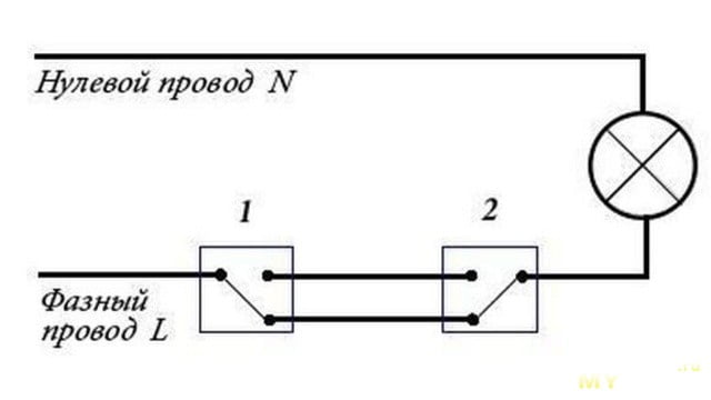
Externally, pass-through switches, and their correct name is pass-through switches, look like an ordinary single-key switch.
Why a switch? The point here is that this device is any key position does not break the electrical circuit, but only switches from one contact to another. that's why- switches .
Here typical diagram lighting control from two places using pass-through switches:

When you press the key of any switch, you can turn the lamp on/off, regardless of the position of the other switch.
I show the phase wire in red, the neutral wire in blue, the switches are labeled No. 1 and No. 2 for convenience.
When you press the key of switch No. 2, the light will go out, since the phase wire in it “breaks” at the place where the red line ends (the green arrow shows in which direction the contact moves):

After this, press the key of the pass-through switch No. 1 and turn on the lamp - the path of electric current through the phase wire is indicated by a red line (this will be the case in all the figures below):

We press the key of the pass-through switch No. 2, the contact flips up and extinguishes the lighting lamp:

Then we press switch No. 1, its contact flips up and turns on the light bulb:

This is how the pass-through switch circuit works to control lighting from two places. In principle, it is not difficult to remember it, despite its apparent complexity.
The main thing is to find the common terminal of the contact on the switch, that is, the terminal in which it does not switch and where the contact is fixed on one side.
Having found these terminals on both switches, we simply connect the phase wire to this terminal to one switch, and the wire from the light bulb to the second.
And we connect the two remaining terminals between the switches in any order - it doesn’t matter. The neutral wire, as usual in the switch circuit, goes to the light bulb directly through the junction box.
In total, this pass-through switch circuit will have 5 wire connections in the distribution box.
By the way, pass-through switches can also be double - that is, two separate independent pass-through switches are placed in one housing; it looks like a regular two-key switch and has six terminals.
Lighting control from three or more places
To do this you will need, as I already mentioned, a cross switch. I won’t show a photo of it, since it also looks like an ordinary single-key switch.
The only external difference is four terminals on the reverse side for connecting wires.
Just like double crossover switches, there are also double crossover switches; they have eight terminals for connecting wires.
So, in order to control the lighting from three places, you will need two pass-through switches and one cross switch.
Pass-through switches are installed at the beginning and end of the line, and crossover switches are installed between them; here is a diagram for connecting pass-through and crossover switches:

Why is the cross switch so named? The fact is that two independent electrical lines pass through this switch and it switches them into a cross.
To understand this, I made two drawings. Figure one - a crossover switch connects electrical lines directly in parallel:

But on this one diagram - electrical the lines intersect each other, hence the name “cross”:

Well, now in more detail -
How does a three-way lighting control circuit work using pass-through and crossover switches?
The cross switch is designated by the letter X (X). The operation of the circuit is indicated by analogy with the above-described circuit of pass-through switches.
Imagine that this is lighting control in the entrance of a three-story building. Pass switch No. 1 is installed on the 1st floor, cross switch is installed on the 2nd floor, and pass switch No. 2 is installed on the third floor.
So, turn on the light (press switch key No. 1) - the light is on, electricity passes along the phase wire as shown in red line:


We go up to the second floor and check the cross switch - press the button, the light turns on:

Press the key back and turn off the light:

We go up to the third floor to the second pass-through switch, press its button - the light turns on:

We leave pass-through switch No. 2 in this position, go down to the 2nd floor and press the cross switch key - turn off the light:

Again, we leave the cross switch in this position and go down to the first floor, press the key of the first pass-through switch - the light turns on:

This is how the lighting control circuit works from three places using pass-through and cross switches.
With this scheme, there will already be 7 connections in the junction box.
If it is necessary to control the lighting not from three, but from four, five or more places, then simply add the required number of cross switches between the passages, that’s all!
For example, here’s what I drew in this diagram:

If you control each light bulb from any floor, then you will have to install three switches on each floor - on the first and third floor there are three pass-through switches, and on the second floor there are three cross switches.
And collect three such circuits - one circuit for each lamp. You can make one double switch, one simple pass-through switch on the first and third floors, and on the second floor you can also make one double cross switch and plus a single cross switch - in this case, there will be two installation boxes for switches on each floor.
But you still have to collect three circuits)))
That's all for me, I hope I clearly explained the circuits of pass-through switches?
Finally, a video on the topic
“How to find the common terminal (clamp) of a pass-through switch”
I will be glad to see your comments, if you have any technical questions, please ask them on the forum, that’s where I answer questions - .
Question: “There are two bedside lamps with separate switches by the bed.
There is a switch by the door. How can I make sure that when I turn on the switch at the door, both lamps turn on, and then at the bed I can turn off one of them or both using the nearby switches?”
Answer: " You will take the very first diagram from this article and add another lamp and another switch to it (duplicate the right side of this diagram). Connect the neutral wire from the second lamp to the zero in front of the first lamp, connect the two wires from the second switch to the corresponding wires coming from the switch at the entrance of the room (the wires between the first and second switches in the diagram from this article). Everything will work, but if you had one lamp on by the bed, the input switch will turn it off, but will light the one that was not on. Explanatory picture below:”


Subscribe to my channel on YouTube ! Watch many more home electrical videos!
If you need to control one lamp simultaneously from different rooms, then use pass-through switch connection diagram. But it is quite difficult to assemble such a circuit using conventional switches; then the use of pass-through switches or switches, as they are also commonly called, is required.
To organize control of lamps from several places, such switches are used. Not only is it very convenient, but it also allows you to save significant energy.
To easily calculate the required number of lamps, use the Calculator for calculating the number of lamps.
Application of pass-through switches especially relevant for controlling the lighting of staircases. For this purpose, circuits using time relays are often used, but such circuits are less economical and reliable, and are also not very convenient to use.
People move up stairs at different speeds, some faster and others slower, so setting large time delays taking into account the reserve means reducing savings.
Connection diagram for a pass-through lamp at the bottom, one switch allows you to turn on the lamps, and going up the stairs, another switch allows you to turn them off. If you need to go down, then to turn on the light a pass-through switch is used at the top, and to turn it off - at the bottom. A similar scheme is convenient to use for lighting long corridors.
Pass-through switches will be very useful not only for owners of long corridors and high-rise buildings, they will also be very useful for residents of small apartments. For example, in an apartment there is a passage room, upon entering which the light turns on, then when you go to the next room, the light turns on in it, and in the passage room it turns off pass-through switch, lighting that has become unnecessary. This scheme is very convenient and eliminates unnecessary walking, and also saves electricity.
Or another example. When an apartment occupant enters the bedroom, the light at the door turns on, and when he goes to bed he turns on the sconce or table lamp to read before going to bed, but now he needs to get up, go to the door and turn off the chandelier. And if in advance install a pass-through switch at the head of the bed, then all these manipulations do not need to be done.
In order to implement such a control circuit, so-called “pass-through switches” are used, which are switches. Unlike conventional switches, they have not two, but three contacts and can switch the “phase” from the first contact to the second or third.
Any type of lamp (from incandescent to fluorescent, LED, and energy-saving) can be used as a lighting source for such a circuit. You can connect according to this scheme not only lamps, but also any other load, the inclusion of which needs to be controlled from several places.
The procedure is not much different connecting a pass-through switch from connecting a conventional switch. The only difference is in the number of wires and contact terminals supplied; there are three of them at the pass-through switch.

It is necessary to take into account in advance that a three-core wire will need to be pulled from the junction box to such a switch.
In this scheme we use two pass-through switches and a distribution box into which wires and three-core wires from switches are brought from the controlled lamp.
From the junction box, the phase wire is connected to the common input contact of the first pass-through switch. Two other (output) contacts are connected to the wires, which come from similar contacts of the second switch. Then it is connected to the wire coming from the lamp, the common (input) contact of the second switch.
The second wire from the lamp is directly connected to the junction box zero
In accordance with the power of the controlled luminaire, it is necessary to select the cross-section of the three-core wire that is supplied to the pass-through switches.
Sometimes it becomes necessary to provide not two control points for lamps, but three or more. For example, on the stairs of a multi-story building, the lights on each floor must be turned on and off. With a long corridor into which the doors of several rooms open, the situation is the same.

To implement this scheme, in addition to simple pass-through switches, you will also need crossover switches. Such switches no longer have three contacts, but four - two input and two output, which represent two pairs of simultaneously switched contacts. A four-wire wire must be connected to such switches accordingly.
Connection diagram for a pass-through switch - control of a lamp from 3 places.
They are used in such a control scheme at the first and last control points of lamps - regular pass-through switches, on all others there are cross switches.
The number of control points is not limited, but the complexity of switching in the distribution box increases due to the large number of wires connected to it. When laying them, you simply cannot do without proper marking of the wires, otherwise you can easily get confused in them.
The connection principle is as follows: the output pair of contacts of the first pass-through switch is connected to wires that go to the input pair of the next cross switch and further, up to the last pass-through switch, the common contact of which is connected to the wire going to the lamp. The phase wire is connected to the input contact of the first switch, and the second wire from the lamp to the junction box zero.
A three-core wire is pulled to each pass-through switch, and a four-wire wire is pulled to each crossover switch.
Pass-through switches allow you to control one model of lighting equipment (lamp, chandelier, floor lamp) from several rooms, and this can be done simultaneously. It is important to know how to connect a pass-through switch so that all lamps work properly. To do this, you should use appropriate diagrams.
Pass-through switches are an indispensable option in private houses, the layout of which includes several rooms located on different floors. Appropriate connection diagrams can be selected for large apartments and institutions with a corridor-type layout. The advantages of such options include not only convenience, but also the opportunity to reduce the amount of electricity consumed: the light is on only where it is needed. In other rooms, the lighting does not turn on, and accordingly, energy is not consumed.
Connecting pass-through switches in the distribution box
Pass-through switches differ from standard models in the following features:
- Their design provides three contacts, in contrast to standard models, which have two contacts
- The equipment allows you to quickly change the “phase” to the second or third contact from the first.
Important! The functions of the light source, under the conditions of the appropriate circuit, can be performed by fluorescent, LED, energy-saving and any other lamps. It is noteworthy that the circuit can be used to connect a load of almost any type, which is controlled from different parts of the room.

Distributor of a group of pass-through switches
Connection diagram: 2 places
For those who are interested in the question of how to connect a pass-through switch, a connection diagram for 2 places will be especially useful. In fact, the process is practically no different from a similar circuit that works in relation to a switch standard type. The main differences are as follows:
- Total number of contact type terminals
- The number of wires that need to be connected to the equipment.
Important: the pass-through switch is connected via three wires and the same number of terminals. You will need a wire with three cores, which will need to be carefully pulled to the switch in the direction from the distribution box.

Control circuit for a group of pass-through switches consisting of two elements
As part of this connection diagram, a distribution box is used, and two pass-through switches are also used. As noted above, wires leading from a chandelier or any other lamp should be placed in the box. Wires with three cores are pulled from the switch. Connecting a pass-through switch according to the diagram from two places involves the use of a phase wire. It is recommended to adhere to the work in the following order:
- From the junction box, the phase wire is pulled to the contact input area on the first switch
- The contacts are fixed on wires that extend from other similar contacts in the design of the second switch
- The input contact of another switch is connected to the wire of a floor lamp, sconce or other lamp installed in the room
- The remaining wire is fixed at zero, and this should be done directly.
Important! The cross-section of a wire with three cores should be selected based on the power of the lighting equipment. If you need to connect several lighting control sections, you will need to purchase cross-type switches. The wiring diagram for the pass-through switch will not work in this case, because several contacts are used, and the wire must have the appropriate number of wires.

Control from two places with two loads
Connection diagram: 3 places
In this case, standard type switches are selected. They are installed in the last and first control sections. For those who want to know how to connect a pass-through switch, a diagram of this type should be clear. It is somewhat more complicated than the connection diagram from three places, but you can understand its specifics. In accordance with it, cross switches should be installed in the remaining sections, that is, not in the last and not in the first.

Connection diagram for three pass-through switches
There can be any number of lighting control sections. Their number determines the complexity of the connection in the distribution box, because many more wires are connected to it. In this case, their correct and orderly labeling will be required. Otherwise, there is a risk that the wires will not be understood.
Work on installing a pass-through switch, the circuit of which is not complicated, is carried out in the following order:
- Two contacts at the output, located in the area of the first switch, are fixed on those wires that are led to the pair at the input of the next cross-type element. This stage is repeated exactly until the last element is connected
- General contact last element is connected to the wire that leads to the floor lamp, lamp, sconce
- A phase-type wire is connected to the contact at the input of the design of the first switch
- The second wire of a lamp, floor lamp or other lighting equipment is fixed to the zero section of the box.
Important! A wire with three cores must be connected to each pass-through element. Wires of four cores are supplied to the cross switches.
Important points
How to disconnect a pass-through switch, connect it - theory and practice will give answers to these questions. It is necessary to clearly understand on what principle the proposed schemes work. Within each of them the same elements are involved:
- Pass-through type switches;
- Boxes;
- Wires, at certain stages replaced by cables;
- Lamps.
The first scheme is considered the simplest. It’s easy to understand how to make a pass-through switch: the neutral wire leads from the power source to the lighting equipment. Plus, it fits in a box. The phase wire is also placed there, but leads through it directly to the contact. All contacts are connected to each other. The phase starts from general contact. The second scheme is somewhat more complex, but it is really convenient.
A simple connection diagram for a pass-through switch
The installation of switches is carried out simultaneously with the installation of the box into which cables from all sources of electricity are routed. In the box they are connected, guided by the selected diagram. It is important to remember that the installation site must be selected correctly, in accordance with the characteristics of the cables, including their length.
The article discusses the operating principle of a pass-through and changeover switch, and provides wiring diagrams for switches designed to control lighting from two, three or more places. Tips for proper execution are provided. installation work related to the connection of pass-through switches.
The idea on which the pass-through switch was created is not new, the first circuits appeared in the homes of radio amateurs back in the 60s, and it gained particular popularity in the 90s, when the first imported switches appeared on the market, “tailored” to control a lamp from different places
Design and principle of operation of a pass-through switch
The simplest representative of the family of pass-through switches is its single-key version.

Externally, it is no different from a regular switch, except for the internal diagram, which is usually indicated on the back of the case.

The operating principle of a pass-through switch is simple: when you move the switch key, the internal moving contact opens one circuit and automatically closes the second (the so-called changeover contact). In the figure, terminal “2” is the common contact, terminals “3” and “6” are the changeover output.
The circuit diagram of the pass-through switch looks like this:

Using this effect, you can create the most simple diagram pass-through switch, in which one lamp will be controlled from two different places at once:
 1,2 - pass-through switches; 3 - to the lamp body
Connecting a pass-through switch
Installation is carried out with a three-core cable. To simplify installation work, its cores must have factory color markings. The cross-section of the selected wire must withstand the load connected through it. Since the power of the switch contacts is limited to 10-16 A, flexible copper cable with a wire cross-section of 1 to 1.5 mm 2 is most often used for installation.
- On the pass-through switch you need to find a common terminal (in the diagram it is indicated by the number “1”).
- We supply a “phase” to the first switch, located closest to the distribution box, and connect it to the common terminal “1”. For installation, we use the brightest wire (usually red or orange, white is used in the explanatory drawing).
- We connect the two remaining wires to the output terminals of the pass-through switch (according to the diagram these are terminals “2” and “3”), remembering the correspondence of the color of the core used and the markings on the terminal block of the pass-through switch.
- On the second switch, we connect the cable in the same way as the first (we strictly observe the color marking of the wires and the corresponding switch terminals).
- In the distribution box we connect the brightest wire (in the explanatory figure it is white), which came from the second pass-through switch with the lamp phase.
- The other two wires, in accordance with the color marking, are connected to a wire of a similar color that came from the first switch (for example, green to green, blue to blue, etc.), in the explanatory figure the green and red wires are connected.
- We immediately connect the neutral and ground wires in the distribution box to a cable of similar purpose that goes to the lamp.
- We tighten the twists, tin them if necessary, and efficiently insulate the exposed sections of the wires.
You can also use the following connection:
 1 - branch box; 2 - to the lamp body; 3, 4 — socket boxes
The pass-through switch is assembled in the following sequence:
1. Disassemble the switch.
2. Connect the wires to the pass-through switch according to the diagram.

3. Insert the switch into the installation box and fix it in it.

4. Cover the switch with protective and decorative covers.

Important! Using a tester, make sure which wire in the distribution box is “phase”. Before carrying out installation work, turn off the supply voltage. Do not twist copper and aluminum wires together.
Checking the operation of the circuit
Make sure that each switch can turn the lamp on or off, regardless of the position of the other switch.


Each switching of the pass-through switch should cause the electric lamps to turn off or on; if this does not happen, it is necessary to find and eliminate the error in the installation performed.
Two-key pass-through switches
These walk-through switches physically consist of two single pass-through switches assembled in one housing.
 1 — pass-through two-key switch; 2 - pass-through switches
A double pass-through switch allows you to control multiple lamps at once. To do this, you need to assemble the following diagram:
 1, 2 — two-key pass-through switch; 3 - to the lamp body
For switching, you can use either three-core wires laid in parallel or six-core wires, the main thing is not to make a mistake when connecting.
The assembled circuit allows you to independently turn on and off two lamps or two lamps from two different places.
For example, let's turn on lamp No. 1 by changing the position of the first rocker switch.

You can turn on the second lamp in the same way.

Disabling can be done using either the first or second switch.
Lighting control from three or more places
In some cases, it is not enough to be able to control the lighting from two places. To effectively control the lighting of a three-story flight of stairs, you will need at least three control points. In this case, together with the classic pass-through switches, an additional type of switch is used - a cross switch.

A crossover switch is installed in the connection gap between two pass-through switches, this allows you to create another lighting control point.
 1, 3 — pass-through switches; 2 - cross switch; 4 - to the lamp body
With the help of additional sequential installation of cross switches, you can increase the number of places from which the lighting is controlled.
As can be seen from the diagram, switching any of the switches will turn the lighting on or off.

Assembling the lamp control circuit from three different places can be done as follows:
 1 — pass-through switch; 2 - cross switch; 3, 5 — socket boxes for pass-through switches; 4 - socket box for cross switch; 6 - branch box; 7 - to the lamp body
Installation is carried out similarly to the option discussed above with a single pass-through switch; installation will require a two- and three-wire cable.
As can be seen from the material discussed, using pass-through switches, you can organize control of one lamp from two different places. Using a cross switch allows you to increase the number of control points to three or more.