Often when repairing various electronic equipment, suspicion arises of a malfunction of bipolar or field-effect (Mosfet) transistors. In addition to specialized instruments and probes for testing transistors, there are methods available to everyone; the simplest tester or multimeter will do the minimum.
As we know, transistors mainly come in two varieties: bipolar and field-effect, their operating principle is similar, but the testing methods are significantly different, so we will consider different testing methods for each transistor separately.
Checking bipolar transistors
Verification methods bipolar transistors are quite simple and for convenience you need to remember that a bipolar transistor is conventionally two diodes with a point in the middle, essentially two p-n junctions.Bipolar transistors have two types of conductivity: p-n-p and n-p-n, which must be remembered and taken into account when checking.

And the diode, as we know, passes current only in one direction, which we will check.
If it turns out that the current flows in both sides of the junction, then this clearly indicates that the transistor is “broken,” but these are all conventions, in reality, when measuring resistance, there should not be “zero” resistance in any of the positions of the transitions being tested - that’s why this There is the easiest way to detect a transistor failure.
Well, now let’s look at more reliable methods of verification in more detail.
And so we set the tester or multimeter to continuity mode (checking diodes), then you need to make sure that the probes are inserted into the correct connectors (red and black), and there is no “discharged” icon on the display. The display should show one and when the probes are closed, zeros (or values close to zero) should be displayed, and a sound should also sound sound signal. And so we were convinced of our choice correct mode multimeter, we can start checking.

And so we check all the transitions of the transistor one by one:
- Base - Emitter - a serviceable junction behaves like a diode, that is, it conducts current only in one direction.
- Base - Collector - a serviceable junction behaves like a diode, that is, it conducts current only in one direction.
- Emitter - Collector - in good condition, the resistance of the transition should be “infinite”, that is, the transition should not pass current or ring in any of the polarity positions.
Depending on the polarity of the transistor (p-n-p or n-p-n), only the direction of the “continuity” of the base-emitter and base-collector junctions depends; with different polarity of transistors, the direction will be the opposite.
How is a “broken” transition determined?
If the multimeter detects that any of the transitions (B-K or B-E) in both polarity switches has “zero” resistance and the sound indication beeps, then such a transition is broken and the transistor is faulty.
How to determine p-n break transition?
If one of the transitions is broken, it will not pass current and will ring in either direction of polarity, no matter how you change the polarity of the probes.
I think everyone understands how to check the transitions of a transistor, the essence of the test is the same as for diodes, we put the black (negative) probe, for example, on the collector, and the red probe (positive) on the base and look at the readings on the display. Then we swap the tester probes and look at the readings again. In a working transistor, in one case there should be some value, usually more than 100, in another case the display should show “1”, which indicates “infinite” resistance.
Checking the transistor with a dial tester
The testing principle is still the same, we check transitions (like diodes)The only difference is that such “ohmmeters” do not have a diode continuity mode and their “infinite” resistance is in the initial state of the needle, and the maximum deviation of the needle means “zero” resistance. You just need to get used to this and remember this feature when checking.
It is best to take measurements in the “1Ohm” mode (you can try up to *1000Ohm limit).

To check in the circuit (without desoldering) Using a pointer tester, you can even more accurately determine the resistance of the junction if it is shunted in the circuit with a low-resistance resistor, for example, a resistance reading of 20 ohms will already indicate that the resistance of the junction is not “zero”, which means there is a high probability that the junction is working. With a multimeter in diode testing mode, the picture is that it will simply show “short circuit” and squeak (of course, it also depends on the accuracy of the device).
If you don’t know where the base is and where the emitter and collector are. Transistor pinout?
Transistors have medium and high power The collector output is always on the housing, which is redesigned for mounting on the radiator, so this does not cause problems. And already knowing the location of the collector, it will be much easier to find the base and emitter.Well, if there is a low-power transistor in a plastic case where all the terminals are the same, we will use this method:
All we need is to measure all combinations of transitions one by one by touching the probes one by one different conclusions transistor.
We need to find two transitions that will show infinity "1". For example: we found infinity between right-left and right-middle, that is, in essence, we found and measured the reverse resistance of two p-n junctions (like diodes), from which the placement of the base becomes obvious - the base is on the right.
Next we look for where the collector is and where the emitter is, for this we measure the direct resistance of the transitions from the base and here everything becomes clear since the resistance of the base-Collector junction is always less compared to the base-Emitter junction.
Fast, accurate transistor testing
If you have a multimeter at hand with a function for testing the gain of transistors, great, the test will take a few seconds, here you just need to determine the correct pinout (unless, of course, it is known).For such multimeters, the test sockets consist of two p-n-p departments and n-p-n, and in addition, each section has three combinations of how a transistor can be inserted there, that is, together there are no more than 6 combinations, and only one is correct, which should show the gain of the transistor, under the conditions that it is working.

Simple sample
In this circuit, the transistor will work as a key; the circuit is very simple and convenient if you need to check transistors often and a lot.
If the transistor is working, when the button is pressed the LED lights up, when released it goes out.
The circuit is presented for n-p-n transistors, but it is universal, all you need to do is put another LED in parallel to the LED in reverse polarity, and when p-n-p check transistor - simply change the polarity of the power source.
If something goes wrong using this method, think about whether the transistor is in front of you and by chance it may not be bipolar, but field-effect or composite.
When checking, composite transistors are often confused when trying to check them. in a standard way, but first of all you need to look at the reference book or “datasheet” with the entire description of the transistor.
How to test a compound transistor
To test such a transistor it is necessary to “start” it, that is, it must seem to be working; to create such a condition there is a simple but interesting way. Using a dial tester set to resistance testing mode (limit *1000?), we connect the probes, positive to the collector, negative to the emitter - for n-p-n (for p-n-p, vice versa) - the tester's needle will not move, remaining at the beginning of the "infinity" scale (for a digital multimeter " 1")
Now if you wet the stick and close it by touching the terminals of the base and collector, the arrow will move because the transistor opens a little.
In the same way, you can test any transistor without even desoldering the circuit.
But it should be remembered that some composite transistors include protective diodes in the emitter-collector junction, which gives them an advantage when working with an inductive load, for example, an electromagnetic relay.
Checking field effect transistors
There is one distinctive point when testing such transistors - they are very sensitive to static electricity, which can damage the transistor if you do not follow safety methods when testing, as well as desoldering and moving. And it is low-power and small-sized field-effect transistors that are more susceptible to static.
What are the security methods?
The transistors should be placed on a table on a metal sheet that is connected to ground. In order to remove the maximum static charge from a person, an antistatic bracelet is used, which is worn on the wrist.
In addition, storage and transportation of particularly sensitive field devices should be with short-circuited leads; as a rule, the leads are simply wrapped with thin copper wire.
Field effect transistor as opposed to bipolar voltage controlled, and not by current like a bipolar one, so by applying voltage to its gate we either open it (for N-channel) or close it (for P-channel).

You can check the field-effect transistor using either a pointer tester or a digital multimeter.
All field-effect transistor terminals should show infinite resistance, regardless of polarity and voltage on the probes.
But if you put the positive probe of the tester to the gate (G) of an N-type transistor, and the negative one to the source (S), the gate capacitance will charge and the transistor will open. And already by measuring the resistance between the drain (D) and the source (S), the device will show a certain resistance value, which depends on a number of factors, for example, gate capacitance and junction resistance.
For the P-channel type of transistor, the polarity of the probes is reversed. Also, for the purity of the experiment, before each test it is necessary to short-circuit the leads of the transistor with tweezers to remove the charge from the gate, after which the drain-source resistance should again become “infinite” (“1”) - if this is not the case, then the transistor is most likely faulty.
A feature of modern high-power field-effect transistors (MOSFETs) is that the drain-source channel is called a diode; the built-in diode in the field-effect transistor channel is a feature of powerful field-effect transistors (a production process phenomenon).
In order not to consider such a “continuity” of the channel as a malfunction, you just need to remember about the diode.
In a working state, the drain-source junction of the MOSFET should ring in one direction like a diode and show infinity in the other (in the closed state - after shorting the terminals). If the junction rings in both directions with “zero” resistance, then such a transistor is “broken” and faulty
Visual method (express check)

- It is necessary to short-circuit the terminals of the transistor
- Using a tester in continuity mode (diode), we place the positive probe to the source, and the negative probe to the drain (a working one will show 0.5 - 0.7 volts)
- Now we swap the probes (the correct one will show “1” or, in other words, infinite resistance)
- We place the negative probe to the source, and the positive one to the gate (open the transistor)
- We leave the negative probe at the source, and immediately put the positive one at the drain, a working transistor will be open and show 0 - 800 millivolts
- Now we can swap the positive and negative probes; in reverse polarity, the drain-source junction should have the same resistance.
- We put the positive probe to the source, and the negative probe to the gate - the transistor will close
- We can check the drain-source junction again, it should again show “infinite” resistance since the transistor is already closed (but remember about the diode in reverse polarity)
The large gate capacitance of some field-effect transistors (especially powerful ones) allows us to keep the transistor open for some long time, which allows us to open it and check the drain-source resistance after removing the positive probe from the gate. But for transistors with low gate capacitance, it is necessary to move the probes very quickly to fix correct work transistor.
Note: for testing P-channel field effect transistor, the process looks the same, but the multimeter probes must be of the opposite polarity. For convenience, you can switch them in places (red to minus, and black to plus) and use the same instructions described above.
When checking a transistor using this method, the drain-source channel can be opened and closed even with your finger, for example, to open it, just touch the gate with your finger while holding the plus with your other hand, and to close it, you still need to touch the gate, but already holding the other finger or second hand minus. An interesting experience that gives an understanding that the transistor is controlled not by current (like bipolar ones) but by voltage.
A simple probe circuit for testing field effect transistors
You can put together a simple and effective circuit for checking field devices that will make it clear enough about the state of the transistor, and you can also switch transistors quickly enough if they need to be checked often and a lot. In some circuits, you can check the transistor even without completely desoldering it from the board.In the process of repairing electronics, it is often necessary to check the functionality of the most common radio components - transistors.
There is a device specially designed for this - R/L/C/Transistor-meter, but it is not always available.
Therefore, it is useful to know how to test transistors, which will be discussed below.
A transistor consists of materials with special electrical properties - semiconductors. The latter are of two types:
- with n-conductivity (electronic);
- with p-conductivity (hole).
The simplest representative semiconductor elements is a diode containing one pn junction.
Transistors are more complex. There are two types of them: bipolar and field.
Bipolar
Also divided into two subgroups:
- with n-p-n junction;
- with p-n-p junction.
The components of a bipolar transistor are called emitter, collector and base. If you imagine this element in the form of two connected diodes, then the base will be their coupling point.
To check a bipolar device, you need to recognize its type (n-p-n or p-n-p) and determine the purpose of the terminals (base, emitter and collector).
Field
 Also divided into two types:
- n-channel;
- p-channel.
In a field-effect transistor, the resistance of the current-carrying section is regulated by the electric field.
The components of the element are called source, drain and gate. The current moves from source to drain, regulation is carried out by the gate.
The design of modern field-effect transistors is supplemented by a diode installed between the source and drain.
Determining the base (gate) output
The easiest way to determine the purpose of the transistor's terminals (pinout) is to download the documentation for it. The search is carried out using markings on the body. This alphanumeric code is typed into the search bar and then “datasheet” is added.
If the documentation cannot be found, the base and other terminals of the bipolar transistor are recognized based on its features:
- pnp transistor: opens by applying negative to the base;
- npn transistor: opens by applying a positive voltage to the base.
They work like this:
- Set up the multimeter: the red probe is connected to the connector with the “V/” icon Ω " (positive potential), black - to the COM connector (negative potential), and the switch is set to the "continuity" mode or, if this is not the case, to the resistance measurement sector (icon " Ω ") to the top position (usually "2000 ohms").
- Define the base. The red probe is connected to the first terminal of the transistor, the black one - alternately to the others. Then red is connected to the second terminal, black again in turn to the 1st and 3rd. A sign that the red one is connected to the base is the same behavior of the device when the black probe comes into contact with other terminals. The device beeped both times or showed a certain final resistance on the display - the transistor is of the n-p-n type; The device was silent both times or displayed “1” on the display (no conductivity) - the transistor belongs to the pnp type.
- Collector and emitter recognition. To do this, connect a probe corresponding to the type of conductivity to the base: for an n-p-n transistor - red, for a p-n-p transistor: black.

Design of a field-effect transistor with a control p-n junction and an n-type channel a) with a gate on the substrate side; b) with diffusion seal
The second probe is alternately connected to the other terminals. When contacting the collector, the display shows a lower resistance value than contacting the emitter.
The terminals of the field effect transistor are usually marked:
- G: shutter;
- S: source;
- D: drain.
If there is no marking, the gate is detected using the same circuit as that of a bipolar transistor.
Field effect transistors are sensitive to static electricity. Because of this, their terminals are short-circuited with foil during storage, and before starting manipulations, wear an antistatic bracelet or at least touch a grounded metal object (instrument cabinet) to remove the static charge.
Checking the transistor with a multimeter
If the purpose of the terminals is known, the bipolar transistor is checked as follows:
- Prepare the multimeter as described above: the switch is moved to the “2K” position in the “ Ω "(resistance measurement) or in continuity mode, the black probe is plugged into the "COM" connector, the red one into the "V/ Ω ».
- Connect the probes to the emitter and collector, then swap them. Normally, in both cases the device does not produce a signal and displays “1”. Some terminal resistance indicates a breakdown.
- Connect a probe corresponding to its type of conductivity to the base: “hole” base (n-p-n type transistor) - red probe, “electronic” (transistor p-n-p type) - black.
- The second probe is connected in turn to the emitter and collector. Test results: the multimeter emits a signal, the display shows a resistance from 500 to 1200 Ohms - the transistor is working; there is no signal and the display shows one - an open circuit.
- Another probe is connected to the base, and the second one is short-circuited in turn with the emitter and collector. Results: no signal, “1” on the display – the transistor is working; the device beeps, the display shows a certain final resistance value - the transistor is broken.
The field device is checked as follows:
- Static electricity is removed from the element.
- Set up the multimeter according to the usual scheme: black probe - into the “COM” port; red - to port “V/ Ω "; switch - to position “2K” of sector “ Ω "(resistance measurement).
- Check the resistance between drain and source: normally the tester displays 400 - 700 Ohms.
- The source and drain are short-circuited in order to reset the junction capacitances, after which the polarity is changed and the measurements are repeated. If the transistor is working properly, the readings change up or down by about 10% (40 - 70 Ohms). An infinitely high resistance between the source and drain (the display shows “1”) indicates a malfunction of the device.
- Check for one-way continuity between source and gate, then between drain and gate. With one polarity of measurements, the multimeter will show a resistance of 400 - 700 Ohms, with the other - unity. Which probe is connected to the gate depends on the type of transistor (n-channel or p-channel). If the conductivity on the drain-gate or source-gate lines is two-way, that is, the device displays a certain final resistance value at any polarity, the transistor is broken.
- When checking an n-channel field switch, the black probe is connected to the drain, the red probe to the source. The channel resistance value is recorded.
- The red probe is connected to the gate, which will lead to a partial opening of the transition.
- Return the red probe to the source and measure the channel resistance. If the transistor is working properly, the resistance will decrease (due to partial opening).
- The black probe is connected to the gate, which will close the transition.
- Return the black probe to the drain and measure the resistance. If the transistor is working properly, it takes on the original value that was recorded.

Transistor test circuit
Check points 6 - 10 for a p-channel field-effect transistor are performed with the opposite polarity - swapping the red and black probes.
The voltage generated by the multimeter is not enough to open the power transistors. In this case, a 12 V power supply is used, connected through a resistor with a resistance of 1500 - 2000 Ohms.
Testing without soldering
A bipolar transistor can be checked without soldering if the circuit is not shunted with low-resistance resistors. Otherwise, instead of a resistance of 500 - 1200 ohms, the multimeter will show only a few tens or even units. Then it is required.
Field-effect transistors are almost always bypassed, so they have to be desoldered before testing.
Gain Determination
When a device fails, another one with a similar gain is selected to replace it. To determine this parameter, you need a multimeter with a transistor testing function. On the switch panel of such a device there is a sector marked “hFE”. It has two rows of ports of three each, which are designated as follows:
- n-p-n;
- p-n-p.

Field effect transistor testing circuit
This is a type of bipolar transistor that needs to be connected to this series ports. The purpose of each port is judged by its letter designation:
- B: base;
- C: manifold;
- E: emitter.
By connecting the transistor leads to the corresponding ports of the appropriate row, the user sees the gain value on the display.
Checking a Composite Transistor
A compound transistor includes two conventional bipolar transistors, and sometimes more. The standard method of checking with a multimeter is not applicable to it. It is necessary to assemble an electrical circuit powered from a constant 12 V power source. “Plus” is connected through a light bulb to the collector, “minus” - to the emitter. The base is connected through a resistor to a switch, which allows you to apply either “plus” or “minus” to it.
The resistor resistance is calculated using the formula:
R = U x h21E /I,
- U - input voltage, V;
- H21E - minimum gain of this transistor;
- I - load current, A.
Consider the following example:
- tested composite transistor: KT827A (h21E = 750);
- lamp power: 5 W.
The load current will be: I = 5 / 12 = 0.42 A.
Then the resistor resistance: R = 12 * 750 / 0.42 = 21600 Ohm, take R = 21 kOhm.
The verification is carried out in two stages:
- Using a switch, “plus” is supplied to the base. If it is working properly, the light will come on.
- The switch short-circuits the base to minus.
If it is working properly, the light will go out.
Even the simplest multimeter, which is not equipped with a function for determining the parameters of semiconductor devices, will help check the performance of the transistor. If you need to select an equivalent one instead of a burnt-out transistor, you will have to look for a tester model with the mentioned function.
The transistor is the most popular active component found in electrical diagrams. Anyone who is interested in electronics needs to check such an element from time to time. Especially often, the test has to be done by beginning radio amateurs who use used transistors in their circuits, for example, soldered from old circuit boards. For “diagnosis”, you can use special testers that allow you to measure the parameters of transistors, so that later they can be compared with those indicated in the reference book. However, for elements included in an amateur circuit, it is enough to check according to the rule: “defective, defective”. This article tells you how to test a transistor with a multimeter using exactly this testing method.
Preparing tools
Every modern radio amateur has a universal tool called a digital multimeter. It allows you to measure constants and alternating currents and voltage, element resistance. It also allows you to check the functionality of circuit elements. Next to the switch for the “dialing” mode, as a rule, there is a diode and a speaker (see photo in Fig. 1).
Figure 1 – Multimeter front panel
Before checking the element, you need to make sure that the multimeter itself is working:
- The battery must be charged.
- When switching to semiconductor test mode, the display should show the number 1.
- The probes must be in good working order, since most devices are Chinese, and breaking the wire in them is a very common occurrence. You need to check them by leaning the tips of the probes against each other: in this case, zeros will appear on the display and a squeak will be heard - the device and probes are working.
- The probes are connected according to the color marking: the red probe goes into the red connector, the black probe goes into the black connector labeled COM.
Verification technologies
Bipolar
The structure of a bipolar transistor (BT) includes 2 p-n or 2 n-p junctions. The terminals of these junctions are called emitter and collector. The output of the middle layer is called the base. Simplified, the BT can be represented as two back-to-back diodes, as shown in Figure 2.
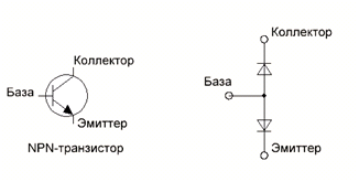
It is not difficult to check a bipolar transistor with a multimeter, as you will now see. As is known to the main p-n property transition is its one-way conductivity. When you connect the positive (red) probe to the anode and the black probe to the cathode, the multimeter display will display the forward voltage at the junction in millivolts. The voltage value depends on the type of semiconductor: for germanium diodes this voltage will be about 200–300 mV, and for silicon diodes from 600 to 800 mV. The diode does not pass current in the opposite direction, so if you swap the probes, the display will show 1, indicating an infinitely large resistance.
If the diode is “broken,” then most likely an audible signal will be heard, and in both directions. If the diode is “open”, then the indicator will display one.
Thus, the essence of checking the health of the transistor is to “test” the p-n junctions base-collector, base-emitter and emitter-collector in direct and reverse connection:
- Base-collector: The red probe connects to the base, the black probe to the collector. The connection must act like a diode and conduct current in one direction only.
- Base-Emitter: The red probe remains connected to the base, the black one connects to the emitter. Similar to the previous point, the connection should conduct current only when connected directly.
- Emitter-collector: In a working junction, the resistance of this section tends to infinity, which will be indicated by a unit on the indicator.
When checking the functionality of a pnp type “diode”, the analogue will look the same, but the diodes will be connected in reverse. In this case, the black probe is connected to the base. The emitter-collector junction is checked in the same way.
The video below clearly shows checking a bipolar transistor with a multimeter:
Field
Field-effect transistors (FETs) or “field-effect transistors” are used in power supplies, monitors, audio and video equipment. Therefore, equipment repair technicians are more often faced with the need to check. You can also independently check such an element at home using a conventional multimeter.
Figure 3 shows the PT block diagram. The Gate (gate), Drain (drain), Source (source) pins can be located differently. Very often manufacturers mark them with letters. If there is no marking, then you need to check the reference data, having previously found out the name of the model.

Figure 3 – Structural scheme PT
It is worth keeping in mind that when repairing equipment that contains PTs, the task often arises of checking the operability and integrity without desoldering the element from the board. Most often, powerful field-effect transistors installed in switching power supplies fail. It should also be remembered that field workers are extremely sensitive to static discharges. Therefore, before checking the field-effect transistor without desoldering, you must wear an antistatic wrist strap and follow safety precautions.
Figure 4 – Antistatic wrist strap
You can check the PT with a multimeter by analogy with checking the continuity of the junctions of a bipolar transistor. A serviceable field device has an infinitely high resistance between the terminals, regardless of the applied test voltage. However, there are some exceptions: if you apply the positive tester probe to the gate and the negative probe to the source, the gate capacitance will charge and the junction will open. When measuring the resistance between drain and source, the multimeter may show some resistance value. Inexperienced technicians often take this phenomenon as a sign of a malfunction. However, this does not always correspond to reality. Before checking the drain-source channel, it is necessary to short-circuit all the PT terminals so that the junction capacitances are discharged. After this, their resistance will become large again, and you can re-check whether the transistor is working or not. If such a procedure does not help, then the element is considered inoperative.
"Field workers" standing in powerful pulse blocks Power supplies often have an internal diode at the drain-source junction. Therefore, when tested, this channel behaves like a regular semiconductor diode. To avoid a false error, before checking the transistor with a multimeter, you must make sure that there is an internal diode. The tester probes should be swapped. In this case, the screen should display one, indicating infinite resistance. If this does not happen, then most likely the PT is “broken.”
The field-effect transistor testing technology is shown in the video:
Composite
A typical compound transistor or Darlington circuit is shown in Figure 5. These 2 elements are located in the same package. There is also a load resistor inside. This model has similar conclusions as the bipolar one. It is not difficult to guess that you can check a composite transistor with a multimeter in the same way as a BT. It should be noted that some types of digital multimeters in test mode have a voltage of less than 1.2 V at the terminals, which is not enough to open р-n junction, and in this case the device shows an open circuit.
Testing semiconductor devices is the most important step in diagnosing faults electronic equipment. Some defective solid-state electronic components show themselves as burnt housing, darkening, etc. If there are simply no such indications of malfunctions, then it’s time to learn how to identify faulty diodes and transistors using a tester. In this article, we will look at how to test simple rectifier diodes, diode assemblies, as well as bipolar transistors using simple equipment. Diodes and bipolar transistors can be checked using a Chinese multimeter.
Regardless of what device you have, you can definitely test any diode and transistor. The main thing is the presence of a special mode, which is indicated in the form of a diode icon. This mode Designed for dialing, as well as for testing semiconductor devices. The multimeter probes must be connected in the same way as in resistance measurement mode: black probe - to COM port, red – to the port for measuring resistance, voltage and frequency. If you have an outdated analog device with a dial indicator of the measurement result, then, probably, such a mode may simply not be there. For such devices, you can use the resistance measurement mode by setting the switch knob to the highest measurement limit.
How to check a diode and diode assemblies made on their basis?
As you know, a diode has 2 working electrodes - a cathode and an anode. A working diode passes current only in the forward direction if you connect the red probe of the device to the anode, and the black probe to the cathode. Connecting the wires in reverse causes the diode to turn off, and its resistance increases almost to infinity. When connecting the multimeter directly, we will notice that the device will indicate the presence of a certain voltage drop. As a rule, this value is several hundred millivolts. Reverse switching is expressed in the absence of any indication of the device. The diode can have only two faults: 1 – open, 2 – short circuit. In the first case, the device will not show any voltage drop in both forward and reverse connection. In the second case, there is infinitesimal forward and reverse resistance. If the device has a sound indication, then the device will beep both in forward and reverse switching on. Four diode rectifier assemblies are tested by testing each of the four diodes in the bridge rectifier.
How to test a semiconductor bipolar transistor?
Before you start testing, you need to determine exactly what type of transistor you are currently testing. In addition to bipolar transistors, there are a great many other types of transistors, which need to be tested in a completely different way. Within the framework of this article, testing of bipolar type transistors will be considered. A bipolar transistor can be represented as an arrangement of 2 diodes. These diodes are connected into a half-bridge using electrodes of the same name. At the output of the transistor there are 3 electrodes, conventionally designated as base, collector and emitter. Depending on the polarity of the diode connection, NPN and PNP transistors bipolar type. The base-emitter junction is a control junction, and the collector-emitter junction is a driven junction. The transistor is designed in such a way that a small current signal, which is supplied to the base-emitter junction, with the correct ratio of resistors in the circuit of the collector, base and emitter junction, causes a higher current signal at the collector-emitter junction.
How to determine where the base, collector, emitter are?
First of all, we note that in any analog tester or digital device, the negative probe is black, and the positive probe is red. Correctly installing the probes, as well as setting the device mode, is very important points. If everything is configured and connected correctly, then determining the pinout of the bipolar transistor will be as easy as shelling pears.
First, you need to determine where the base is. Regardless of whether the experimental transistor has a PNP or NPN structure, we can make the assumption that the base junction is the first electrode. We connect the black probe of the multimeter to the first electrode, and the red one, alternately, to the second and third electrode. Continue searching the base until you find a location where the meter begins to indicate a certain voltage drop, expressed in millivolts. Having noticed an indication of a voltage drop on a certain pair of electrodes, we can say with confidence that either a base-emitter pair or a base-collector pair has been found. Then you need to find the location and polarity of the remaining second pair. Basically, you have to find a pair of diodes whose common electrode is the base. The base can have a negative polarity in the case of a PNP structure, as well as a positive polarity in the case of a PNP polarity. You can check the operation of the transistor already at this stage, because the faulty element will have one of the transitions shorted or broken.
Secondly, when you have already decided on the base electrode, it remains necessary to determine where the emitter is located and where the collector is. Either using the semiconductor test mode on a digital device, or using the resistance measurement mode on an analog device, you need to determine which junction has the highest voltage drop and resistance. We connect the measurement of base-emitter and base-collector diodes in direct connection. We write down the values and compare. As a rule, the difference is not large, but in fact the junction with the emitter electrode turned on will have a slightly higher resistance and voltage drop. Finally, we note that the correctness of the determination of the electrodes can be checked by connecting the transistor to the socket for measuring the parameters of bipolar transistors. If the device shows the h21e parameter close to what is indicated in the datasheet, then the location of the electrodes can be considered correct.
Greetings to all electronics lovers, and today, in continuation of the topic of using a digital multimeter, I would like to tell you how to check bipolar transistor using a multimeter.
A bipolar transistor is a semiconductor device that is designed to amplify signals. The transistor can also operate in switching mode.
The transistor consists of two p-n junctions, with one of the conduction regions being common. The middle overall region of conduction is called the base, the outermost regions the emitter and the collector. As a result, n-p-n and p-n-p transistors are separated.
So, schematically a bipolar transistor can be represented as follows.
Figure 1. Schematic representation of a transistor a) n-p-n structure; b) p-n-p structures.
To make the issue easier to understand p-n junctions can be represented in the form of two diodes connected to each other by electrodes of the same name (depending on the type of transistor).

Figure 2. Representation of an n-p-n transistor structure in the form of an equivalent of two diodes connected with anodes to each other.

Figure 3. Presentation pnp transistor structure in the form of an equivalent of two diodes connected with cathodes facing each other.
Of course, for a better understanding, it is advisable to study how the pn junction works, or better yet, how the transistor works as a whole. Here I will only say that in order for current to flow through the p-n junction, it must be turned on in the forward direction, that is, a minus must be applied to the n-region (for a diode this is the cathode), and a minus to the p-region (anode).
I showed this to you in video for the article “How to use a multimeter" when checking a semiconductor diode.
Since we presented the transistor in the form of two diodes, then, therefore, to check it you just need to check the serviceability of these same “virtual” diodes.
So, let's start checking the transistor n-p-n structures. Thus, the base of the transistor corresponds to the p-region, the collector and emitter to the n-regions. First, let's put the multimeter in diode testing mode.

In this mode, the multimeter will show the voltage drop across the pn junction in millivolts. The voltage drop across the pn junction for silicon elements should be 0.6 volts, and for germanium elements - 0.2-0.3 volts.
First, let's turn on the p-n junctions of the transistor in the forward direction; to do this, connect to the base of the transistor red(plus) multimeter probe, and to the emitter black(minus) multimeter probe. In this case, the indicator should display the value of the voltage drop at the base-emitter junction.


It should be noted here that the voltage drop across the junction B-K there will always be less voltage drop across the junction B-E. This can be explained by lower junction resistance B-K compared to transition B-E, which is a consequence of the fact that the conductivity region of the collector has a larger area compared to the emitter.
Using this feature, you can independently determine the pinout of the transistor, in the absence of a reference book.
So, half the job is done, if the transitions are working properly, then you will see the voltage drop values across them.
Now you need to turn on the p-n junctions in the opposite direction, and the multimeter should show “1”, which corresponds to infinity.
Connecting black probe to the base of the transistor, red to the emitter, and the multimeter should show “1”.

Now we turn on the transition in the opposite direction B-K, the result should be similar.

The last check remains - the emitter-collector transition. Connecting red multimeter probe to the emitter, black to the collector, if the transitions are not broken, then the tester should show “1”.

Changing the polarity ( red-collector, black- emitter) result – “1”.

If, as a result of the test, you find that this method does not comply with this method, this means that the transistor faulty.
This technique is suitable for testing only bipolar transistors. Before testing, make sure that the transistor is not field effect or compound. Many people use the method outlined above to try to check precisely composite transistors, confusing them with bipolar ones (after all, the type of transistor can be incorrectly identified by the markings), which is not the right solution. You can correctly find out the type of transistor only from a reference book.
If there is no diode test mode in your multimeter, you can check the transistor by switching the multimeter to the resistance measurement mode in the “2000” range. In this case, the testing methodology remains unchanged, except that the multimeter will show p-n resistance transitions.
And now, by tradition, an explanatory and complementary video on checking the transistor: