Content:
When insulated conductors are used, it is often necessary to ensure the reliability of the insulation of the current-carrying conductors. Deep damage invisible to the naked eye, especially when it extends all the way to the metal of the conductor, is a capillary. If the damage is covered with a very small amount of moisture, a conductive channel will appear.
In this case, the life of the conductor will decrease the faster the higher the voltage at which the conductor is used. To monitor the condition of the insulation of wires and cables, you need a special device that provides special conditions measurements. This device is a megohmmeter. Next we will talk in more detail about its use.
Design features and their impact on the use of the device
In principle, we are talking about a type of tester (multimeter) operating in resistance measurement mode. In this mode, any of the models of these devices uses a built-in power supply. But in the megohmmeter it is high voltage. For this reason, it is not recommended to hold the probes of this device with unprotected hands while operating it. Depending on the model, there may be several voltage values, and all of them are unsafe for humans.
- To avoid exposure to high voltage, you must first connect the probes in a certain area of the conductor being tested, and only then can the device's power supply be turned on.
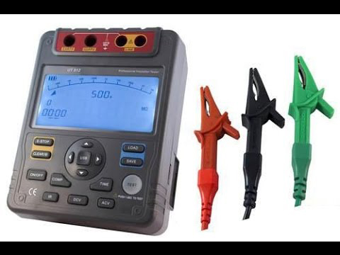
Both models with an analog dial indicator and modern megohmmeters are characterized by some noticeable features. The reader can see them in the image below. Before the appearance digital technologies All measuring devices used dial indicators. Such devices are reliable and durable. That's why they are still used today. The megohmmeter, produced back in the “pre-semiconductor” times, could only be made with an electromechanical voltage converter.
The design of the device used a dynamo, which best ensured a controlled high voltage by rotating the handle. It is a detail that directly indicates the purpose of the electrical measuring device. In modern megohmmeters, high voltage is generated by a generator using semiconductor elements. That's why it doesn't have a handle. But the front panel, on which the regulators are located, as well as the scale, contain voltage in kilovolts.
They are complemented separate button starting the measuring cycle. Therefore, based on the listed signs, it is possible to determine that you have a megohmmeter in front of you. Even if you do not know the language in which the design of the device and its technical documentation. Regardless of how long ago the model was produced, when working, for example, with three-phase cables or wires, the equivalent circuit will be the same (shown below).

High voltage is necessary both to obtain more meaningful current values, which are easier to measure, and to simulate overvoltages, which are characteristic of most electrical networks and are a major source of problems with conductor insulation. Its value is made calibrated, that is, known and maintained at the same value. Therefore, according to Ohm's law, it can be divided by the current strength and the resistance value can be obtained, displayed on a scale.
Measurement progress
Due to the high voltage power supply used in the device and the associated danger to the user, it is recommended that next steps. First of all, the conductor being tested is disconnected from the rest of the electrical circuit. And before this, the circuit is de-energized in one way or another, that is, with a switch, circuit breaker or by unscrewing the plugs, if they are still in use.
Insulation testing is always associated with monitoring earth leakage currents. Therefore, effective grounding is necessary at the place where the megohmmeter is used. A stranded wire with a diameter of 1.5–2 square meters is connected to it. mm. It is designed to nullify the capacitance inherent in wires and cables. To do this, you can use an additional probe from a multimeter or tester, if available. Or make an analogue of it from available materials that is convenient for use.
Before checking extension cords, their plugs are removed from the sockets (as for checking the electrical wiring of sockets). And the conductors and cables of the lighting circuits are checked after removing the lamps from the sockets. The same applies to other electrical appliances whose insulation is checked. They should not be part of the electrical circuit when the megohmmeter is operating.

What security measures should be taken
If the insulation test is not carried out privately, working with a megohmmeter is permitted to a person with an electrical safety permit of at least group three and with a partner. At home, electrical safety is based only on self-control. Therefore, in order not to suffer from high voltage, the instructions are strictly followed. It is the same for any model and contains the following main points:
- Do not touch the operating device and probes without dielectric gloves.
- In order to protect the rest of the company’s employees not participating in the inspection, as well as in an apartment building on the staircase, use standard posters at the place of work

Standard warning posters, or self-made noticeable inscriptions of similar content.
- Do not touch or handle the metal parts of the probes, even with gloves.
- Start each measurement by grounding the conductor being tested, and also complete the test with the same action (touching to remove residual voltage). The relevance of this procedure is directly proportional to the length of the wire or cable that is being tested.
- If there is no information about the built-in device for self-discharge of the device after turning it off, short-circuit the probes.
Correct connection to the conductor under test
The megohmmeter performs two measurements:
- two identical probes are used to check the insulation, for which the first probe is connected to the ground or one of the conductors, and the second to the other conductor (terminals G - ground and L - line);
- The third double probe connects the conductor screen (terminal E) and the core (terminal L) to the device. This eliminates leakage currents.

Selection of test voltage and measurement results
For various elements of electrical networks, the PUE establishes the correspondence of the test voltage and insulation resistance. Some of this data is presented below in table form.

Checking the electrical wiring
If you check the electrical wiring in an apartment or private house yourself, this measurement procedure is recommended.
- First of all, everything that uses detachable connections is turned off (plugs and lamps were already mentioned above).
- Then the grounding is connected to the core.
- According to the table, the range in which the expected resistance value is located is selected, and the device is adjusted to it.
- The absence of voltage is checked on the core (line) (the user decides whether to use a multimeter or a voltage indicator for this).
- Depending on the presence of a screen, two or three terminals with corresponding types of probes are used.
- The grounding is removed.
- Depending on the model (it has a semiconductor generator or an electromechanical one), by pressing a button or rotating a handle, voltage is applied to test the conductor.
- We record the result obtained in a convenient way.
- We touch the core with grounding to remove residual voltage and disconnect the probes.
- We connect the probes briefly, and after that the measurement is completed.
The results obtained are compared with the table ones. If the insulation resistance values are less than the recommended values, this means that either the wiring is worn out or the insulation is damaged. It is better to replace the old wiring. In the new one it is worth trying to find the reason for its low resistance.
Checking the cable
Do not forget to disconnect everything that was connected to the cable being tested. If the cable has two cores, the measurement procedure is the same as for electrical wiring (see above). If there is a screen, a double probe is used. If there are several veins, you will have to perform a check for each of them similar to that done for their pair.

But to fully understand the state of the insulation in this cable, two more measurement options will be required.
- During the testing process, all conductors, except one being tested, together with the screen are connected to the device with one probe. And the core being tested is connected with another probe to terminal L.

Each core is tested against a grounded shield.
But it makes sense to perform all three options only after receiving negative results from the first test option. Elements in distribution boards are checked only after they are switched off and then the residual voltage is removed. Electrical machines are tested in the same way. The test voltage must correspond to the recommended value for the product being tested.
All test options use voltage exposure for at least one minute. The readings are recorded after approximately fifteen seconds from the start of voltage application.
Megohmmeters are convenient and functional devices for measuring insulation resistance; they allow you not only to take accurate measurements, but also to verify the integrity of the insulating material. Insulation resistance meters are used mainly by professional electricians and specialists servicing high-voltage electrical equipment, which is due to the features of such a device. The device allows you to measure large values in the resistance of circuits, insulating materials, engines, telecommunications installations and other types of equipment, and the main purpose is to determine the operational safety of the objects being tested.
Megaohmmeter: what is it, scope and principle of operation
A megohmmeter is a special meter used to measure high resistance values. The main difference from traditional ohmmeters is that measurements are carried out at a significant voltage level, independently generated by insulation meters.
The functioning of insulation resistance meters is explained by Ohm's law, which operates in a section of an electrical circuit: I=U/R. The main components installed inside the housing are represented by a voltage source having a constant and calibrated value, as well as a current meter and terminal outputs.
The connecting wires are fixed to the terminals using conventional alligator clips, and the current values of the electrical circuit are measured using the ammeter present. Some models are characterized by the presence of a scale with two types of values or numbers displayed on the screen.
Operating principle of a megohmmeter
Megohmmeters are used to measure insulation resistance, as well as to determine the insulation absorption coefficient of electrical equipment that is not under operating voltage conditions. Insulation resistance meters are classified depending on the typical features of the circuit and indication method.
Digital models are cheaper devices, while analog devices are expensive, but are distinguished by high accuracy of measurements. The main area of application is currently represented by production and distribution systems of electrical energy, control systems for the operation of electrical equipment in industry, laboratories and in field conditions. In everyday life, such devices are not in great demand.
How the device works
Different models of meters differ in their design features. Old devices have manual dynamos inside them, while new devices are supplied with external and internal sources.

The diagram shows the elements of a megohmmeter
- “L” – “Line” clamp;
- “E” – “Screen” clamp.
- “Z” – “Earth” clamp;

The output power of devices designed to test the insulation of industrial high-voltage equipment can be several times higher than the characteristics of models designed to work in household electrical wiring conditions
The design feature of the measuring head is the frame interaction, and the switch toggle switch is responsible for the switching support. The reliable and durable dielectric housing is equipped with a portable handle, a portable generator-folding handle, a switch and special output terminal elements.
Features of device operation
Any measuring activities in electrical installations are carried out exclusively by serviceable, necessarily tested and fully inspected electrical instruments or devices with strict adherence to all the rules of the measurements taken.

Before starting measurements, make sure the megohmmeter is in working order.
Megaohmmeters are selected for the purpose of checking the insulating properties and measuring the resistance of dielectrics according to established indicators.
Influence of induced voltage
The electricity that is carried by the wires of electric transmission lines creates a large magnetic field that changes according to a sinusoidal law. This feature provokes the induction in metal conductors of an electromotive secondary force and current indicators of significant magnitude.

Electricity transmitted by power lines creates a powerful magnetic field
This feature has a significant impact on the level of accuracy of all measurements performed, and the resulting sum of a pair of unknown current values can make the metrological task very problematic. It is for this reason that measuring the resistance of network insulation under voltage conditions is an absolutely futile exercise.
Effect of residual stress
The generation of voltage parameters by the generator, which enters the measured electrical network, contributes to the appearance of a potential difference between the grounding circuit and the wires, which is accompanied by capacitive formation with the presence of a certain charge.

Before connecting for measurements, you need to make sure there is no residual voltage
Immediately after disconnecting the measuring conductor, a rapid break in the electrical circuit occurs, which contributes to partial conservation of potential due to the creation of a capacitive charge inside the bus or wire system. If you accidentally or intentionally touch this area, there is a risk of electrical injury when a current discharge passes through the body. Injury prevention is ensured by the use of mobile system grounding with a handle provided with high-quality insulation.
Before connecting to perform insulation measurements, it is important to ensure that there is absolutely no residual charge or voltage inside the circuit being tested. For this purpose, specialized indicator devices or voltmeters with appropriate nominal values are used. For quick and absolutely safe operation, you will need to connect one end of the grounding conductor to the ground loop. The other end on the conductor is made contact with the insulation rod, which allows grounding to eliminate residual charge.
How to use the device
When rotating the handle of a hand-held device or pressing a button electronic devices High voltages are supplied to the terminal outputs, which are supplied through wires to the electrical circuit being measured or to electrical equipment. When taking measurements, resistance values are displayed on the scale or screen.
Table: megohmmeter parameters during measurements
| Element | Minimum insulation resistance | Meter voltage | Peculiarities |
| Electrical products and devices with a voltage level within 50 V | Correspond to the passport data, but not less than 0.5 MOhm | 100 V | During measurements, semiconductors are efficiently shunted |
| Electrical products and devices with voltage levels in the range of 50–100V | 250V | ||
| Electrical products and devices with voltage levels in the range of 100–380V | 500–1000V | ||
| Electrical products and devices with voltage levels in the range of 380–1000V | 1000–2500V | ||
| Distribution devices, electrical panels and current wires | Not less than 1 MOhm | 1000–2500V | Each section in the switchgear is measured |
| Electrical wiring, including lighting networks | Not less than 0.5 MOhm | 1000V | Inside hazardous areas, measurements are carried out annually, in others - every three years. |
| Stationary electric stoves | Not less than 1 MOhm | 1000V | Measurements are carried out on heated and switched off stoves annually |
Safety rules when working with the device
Modern megohmmeters generate a voltage level within 2500 V, so only workers who have undergone training can perform work with such a device. full course special training and familiar with safety regulations. Only fully functional and verified measuring instruments may be used in the work. Measurements on short-circuited wires show the magnitude of the insulation resistance.
On older resistance meters, this value is equal to “infinity”.

Be sure to study the safety rules when working with the device
When operating an electronic device equipped with a modern digital display, the measurement indicators are always fixed.
- When performing insulation resistance measurements, any touching of the output terminals of the measuring device and contact with the bare parts of the connecting wires in the form of the ends of the probe are strictly prohibited. Do not touch bare metal parts of the electrical circuit being measured in equipment under high voltage.
- It is strictly prohibited to measure insulation resistance without checking the absence of voltage if measures are planned with the conductors of the electric cable or with any live parts of electrical installations. Checking for the presence or absence of voltage in wires and installations is carried out using an indicator, a special tester or a voltage indicator.
- Measurement activities are prohibited if there is a residual charge on electrical equipment. To remove the residual charge, an insulating rod or grounding with a short-term connection to the current-carrying sections of the device must be used. The residual charge is eliminated after all measurements have been carried out.
The use of a megohmmeter that has undergone inspection and standard testing is possible only after its performance has been confirmed. It is necessary to verify the correct operation of such a measuring device immediately before measuring the insulation resistance. For this purpose, connecting wires are connected to the output terminals, after which a wire short-circuit is performed, which allows you to begin measurements. It should be remembered that in conditions of shorted wires, the resistance readings should be zero, and shorted connecting wires allow you to verify their integrity.
Is there an alternative to a megohmmeter?
Today, a huge number of multimeters are sold that measure resistance levels in the range of up to 100 MOhm. Despite their solid operating range, such testers cannot be a worthy replacement for a megohmmeter, which simultaneously checks the electrical insulation strength and ensures operation with measuring voltages of 250, 500, 1000 V and even more.

The principle of measuring insulation resistance with a megohmmeter
Currently, the most common measuring instruments include the M-4100, ESO202/2G and MIC-1000 megohmmeters, as well as the MIC-2500.
Certified megohmmeters: review of manufacturers
The main, most significant technical characteristics and parameters of megohmmeters include:
- resistance - within 0–49,900 MΩ;
- voltage - 100–5000 V;
- operating temperature ranges - from -20 to + 40°C.
Megaohmmeters, which undergo periodic testing of their performance in METROLOGY and are included in the Register of Measuring Instruments of Russia, are produced by many manufacturers, but the guaranteed safe and reliable models of the measuring device have proven themselves best.
Table: list of devices with characteristics
| Model | Device type | Voltage, V |
Range, gOhm |
PC connection | Nutrition |
Price, rub. |
| 1801 IN | analog | 250 | up to 1 | No | AA batteries | up to 5000 |
| MI 2077 | digital | 5000 | up to 10000 | No | battery | 50–75 thousand |
| MI 3202 | digital | 5000 | up to 10000 | Yes | battery | 50–75 thousand |
| MIC-1000 | digital | 1000 | up to 100 | Yes | battery | 20–50 thousand |
| MI 3103 | digital | 1000 | to 10 | No | AA battery | 10–20 thousand |
| MI 3201 | digital | 5000 | up to 10000 | Yes | battery | 50–75 thousand |
| MI 3200 | digital | 10000 | up to 10000 | Yes | battery | >75 thousand |
| MIC-2510 | digital | 1000 | to 10 | Yes | battery | 20–50 thousand |
| MIC-2500 | digital | 2500 | to 10 | Yes | battery | 20–50 thousand |
| MIC-30 | digital | 1000 | to 10 | Yes | battery | 20–50 thousand |
| E6–24/1 | digital | 1000 | to 10 | No | battery | 20–50 thousand |
| M 4122 U | digital | 2500 | up to 300 | Yes | battery | 20–50 thousand |
| M 4122 RS | digital | 2500 | up to 100 | Yes | battery | 10–20 thousand |
| ESO 202–1G | digital | 500 | to 10 | No | r/generator | 10–20 thousand |
| DT 5500 | digital | 1000 | to 10 | No | AA batteries | 10–20 thousand |
| DT 5503 | analog | 1000 | up to 1 | No | AA batteries | up to 5000 |
| DT 5505 | digital | 1000 | to 10 | No | AA batteries | 10–20 thousand |
| 1800 IN | analog | 1000 | up to 1 | No | AA batteries | up to 5000 |
| 1832 IN | analog | 1000 | up to 1 | No | AA batteries | 5–10 thousand |
| 1851 IN | digital | 1000 | up to 1 | No | AA batteries | 5–10 thousand |
| MIC-3 | digital | 1000 | to 10 | No | AA batteries | 10–20 thousand |
Less popular among consumers, but well-proven models of digital and analog megohmmeters.
Table: characteristics of digital and analog megohmmeters
| Model |
Type device |
Voltage, V |
Range, gOhm |
PC connection | Nutrition |
Price, rub. |
| 4101 IN / 4102 MF | digital | 250–1000 | to 10 | No | AA batteries | 5–10 thousand |
| 4103 IN / 6210 IN | digital | 500–5000 | up to 300 | No | AA batteries | 5–10 thousand |
| 4104 IN / 6211 IN / 6212 IN / 6201 IN |
digital | 10000 | up to 500 | No | battery | 20–50 thousand |
| 2732 IN | analog | 250–1000 | up to 1 | No | AA batteries | 5–10 thousand |
| MIC-5000 | digital | 250–5000 | up to 10000 | No | battery | >75 thousand |
| ESO 202–2G | digital | 250–2500 | up to 1 | No | r/generator | 5–10 thousand |
A megohmmeter is certainly one of the most necessary devices when working with high-voltage equipment. The choice of model and, most importantly, the safety rules for its use should be treated with maximum responsibility.
All electrical installations and systems in operation require mandatory electrical measurements to determine the general condition, safety and performance of electrical networks, including checking insulation resistance parameters. These measurements will require working with a megohmmeter, a device designed for the timely detection of insulation defects. To use a megohmmeter you need to study it specifications, operating principle, device and specific features.
Megaohmmeter device
 A megohmmeter is a device designed to measure large resistance values. His distinctive feature is to perform measurements at high voltages generated by its own converter up to 2500 volts (voltage varies depending on different models). The device is often used to measure the insulation resistance of cable products.
Regardless of the type, the megohmmeter device consists of the following elements:
- voltage source;
- ammeter with instrument scale;
- probes, with the help of which the voltage from the megohmmeter is transferred to the object being measured.
Working with a megohmmeter is possible thanks to Ohm's law: I=U/R. The device measures the electric current between two connected objects (for example, 2 wire cores, wire to ground). Measurements are carried out using a calibrated voltage: taking into account the known values of current and voltage, the device determines the insulation resistance.
Most megaohmmeter models have 3 output terminals: ground (G), line (L); screen (E). Terminals Z and L are used for all measurements of the device; E is intended for taking measurements between two similar live parts.
Types of megohmmeters
Today there are two types of megohmmeters on the market: analog and digital:

Working with a megohmmeter
 To work with the device, you need to know how to measure insulation resistance with a megohmmeter.
The whole process can be divided into 3 stages.
Preparatory. During this stage, it is necessary to ensure the qualifications of the performers (specialists with an electrical safety group of at least 3 are allowed to work with a megohmmeter), resolve other organizational issues, study the electrical circuit and turn off the electrical equipment, prepare instruments and protective equipment.
Basic. As part of this stage, in order to correctly and safely measure insulation resistance, the following procedure for working with a megohmmeter is provided:
- Measuring the insulation resistance of connecting wires. The specified value should not exceed the upper limit of measurement (URL) of the device.
- Setting the measurement limit. When the resistance value is unknown, the highest limit is set.
- Checking the object for absence of voltage.
- Shutdown semiconductor devices, capacitors, all parts with reduced insulation.
- Grounding the electrical circuit under test.
- Recording of instrument readings after a minute of measurements.
- Taking readings when taking measurements of objects with large capacitance (for example, long wires) after the needle has stabilized.
- Removing the accumulated charge by grounding at the end of the measurements, but before disconnecting the ends of the megohmmeter.
Final. At this stage, the equipment is prepared for voltage supply and documentation for measurements is drawn up.
Before you start taking measurements, you need to make sure the device is working properly!
There is a way to check the megohmmeter for serviceability. It is necessary to connect wires to the terminals of the device and short-circuit the output ends. Then voltage is required and the results must be monitored. A working megohmmeter shows the result “0” when measuring a shorted circuit. Next, the ends are separated and repeated measurements are taken. The screen should display “∞”. This is the insulation resistance value of the air gap between the output ends of the device. Based on the values of these measurements, we can draw a conclusion about the readiness of the device for operation and its serviceability.
Safety rules when working with a megohmmeter
 Before you start working with a resistance meter, you must familiarize yourself with the safety precautions when using a megohmmeter.
There are a number of basic rules:
- Probes should be held exclusively by isolated areas limited by stops;
- Before connecting the megohmmeter, it is important to make sure that there is no voltage on the device and that there are no strangers in the work area.
- It is necessary to remove the residual voltage by touching the portable ground of the electrical circuit being measured. The ground must not be disconnected before the probes are installed.
- All work with a megohmmeter according to the new rules is carried out wearing protective dielectric gloves.
- After each measurement, it is recommended to connect the probes to remove residual stress.
To work with a megohmmeter in electrical installations, the device must pass appropriate tests and be verified.
Measuring the insulation resistance of wires and cables
 A megohmmeter is often used to measure the resistance of cable products. Even for novice electricians, if they know how to use the device, it will not be difficult to check a single-core cable. Checking a multi-core cable will require a lot of time, since measurements are taken for each core. In this case, the remaining wires are combined into a bundle.
If the cable is already in use, before starting to measure the insulation resistance, it must be disconnected from the power supply and the load connected to it must be removed.
The control voltage when testing a cable with a megaohmmet depends on the voltage of the network in which the cable is operated. For example, if the wire operates at a voltage of 220 or 380 volts, then for measurements it is necessary to set the voltage to 1000 volts.
To take measurements, one probe must be connected to the cable core, the other to the armor, and then apply voltage. If the measurement value is less than 500 kOhm, then the wire insulation is damaged.
 Before you start checking the electric motor with a megohmmeter, it must be de-energized. To perform the work, it is necessary to provide access to the winding terminals. If the operating voltage of the electric motor is 1000 volts, for measurements it is worth setting it to 500 volts. For measurements, one probe must be attached to the engine body, the other one in turn to each terminal. To check the connection of the windings to each other, probes are installed simultaneously on pairs of windings. Contact must be with metal without traces of paint or rust.
This is an informational article for informational purposes only. More detailed and accurate information is contained in the instructions for using megaohmmeters, technical and regulatory documents.
Video instructions for working with a megohmmeter
What is the correct name for this device for measuring insulation resistance, Megaohmmeter or Megohmmeter?! Almost every device user probably asked this question. And it seems that the essence of the work and measurements will not change from the name, but I want to not only measure correctly, but also speak.
If you search on the Internet for the correct name for a device for measuring insulation resistance on a network, you can come across the name both “megaohmmeter” and “megger”. Since the Internet adapts to people’s needs, it is useless to look for the truth here. Wikipedia says that the device is called a “megohmmeter”, but this name is outdated and you need to use a “megaohmmeter”, that is, the situation is not particularly clear.
Megaohmmeter UNI-T UT502A
In order to still find out what to call this device, you need to return, so to speak, to the original source, in this case to the manufacturer.
As it turned out, the Uman plant, called “Megger,” began producing megohmmeters in 1957. But, it would seem, everyone got to the bottom of the truth, but it was not so, on the instruments that the plant produces there is the inscription “megaohmmeter”.
If you’re really interested, you can look for books about this device to make your task easier, I’ll say. The books say “megohmmeter”, however, the year of publication is 1963. In modern books the name “megohmmeter” is more common.
And again, it is not clear what to correctly call this miracle device, which helps and makes the life of an electrician a lot easier: Megaohmmeter or Megohmmeter.

Megaohmmeter ES0202/2G
A device that measures megaohms, gigaohms, and now logically more, should still be called a Megaohmmeter. But the logic is debatable, based on all this, we can conclude that it is not particularly important what you call the device Megaohmmeter or Megger. The main thing is that before use you carefully study the operating instructions and adhere to safety rules. And the name is just a name, accurate and clear measurements are more important.
At the same time, if you fill out documents, you need to write “Megaohmmeter,” as Wikipedia says, otherwise according to GOST it is not allowed. From this the conclusion suggests itself that the Megaohmmeter would be correct. But if you are used to saying Megger all the time, then there is no need to relearn it, they will understand you anyway.
The resistance of a cable's insulating layer is one of the most important parameters of its performance. If you bought a cable and it was stored in a warehouse for some time, do not think that its insulation will be the same as when you bought it. Insulation can deteriorate both under unsatisfactory storage conditions and during operation and installation. In order to reveal everything possible problems and the cable insulation is checked with a megohmmeter.
Causes of poor cable insulation
There are several factors affecting the insulating properties of cables:

In order to identify an insulation problem in time, you will need a special device - a megohmmeter. These devices are of the old type (mechanical, where you need to rotate the handle):
 and a new model - electronic:
 Let's consider the operation of these devices.
Safety regulations
Checking the cable insulation with a megohmmeter is carried out only with the equipment disconnected and de-energized.
The megaohmmeter is capable of producing high voltage (certain types up to 5000 Volts), so when working with it, strictly follow the following rules:


Preparatory work
The cable under test must be prepared before testing.
 For this:
- ⚡ check that there is no voltage on the cable cores
- ⚡
long cables may have induced or residual voltage
Therefore, before each measurement, using a separate piece of wire or portable grounding, wearing dielectric gloves, it is necessary to touch the core and the grounded body or grounding loop to remove this charge; - ⚡
disconnect the cable from the connected equipment.
This must be done so that when checking the cable insulation with a megohmmeter, only the cable itself is involved in the test, without the equipment or machines to which it is connected. Disconnection must be done on both sides of the cable. Sometimes this is not done to speed up work. First, a measurement is taken, and if it shows a negative result, then only after that the wires are pulled back.
Checking the megohmmeter
Before checking the cable insulation with a megohmmeter, it is necessary to test the operation of the device itself.
Here's how to do it on the M4100 megohmmeter. The device has 2 scales: the upper one for measurements in megaohms and the lower one for measurements in kiloohms.
To work in megaohms:
- ⚡ connect the ends of the probe wires to the two left terminals. The probes must be open;
- ⚡ rotate the knob and watch the arrow readings. If the device is working properly, it will tend to the left - towards infinity;
- ⚡ close the probes together. When you rotate the knob, the arrow should deflect to the right to zero.
To work in kilo-ohms:
- ⚡ Place a jumper between the 2 left terminals and connect one of the ends there. The second end is connected to the rightmost terminal. The probes are open;
- ⚡ Rotate the knob and watch the readings. When the device is working properly, the arrow deviates as far as possible to the right;
- ⚡ After closing the probes and rotating the knob, the arrow will tend to zero on the lower scale (i.e. to the left).
Working with megaohmmeter M4100
- First of all, check that there is no voltage on the cable
- ground all conductors
- place the device on a flat surface
- When measuring conductor insulation to ground, one of the probes is connected to the wire, the other to the armor or grounding device. Then remove the grounding only from the core being measured;
- Rotate the knob evenly for 60 seconds. Rotation speed is two revolutions per second. At 60 seconds, note the readings of the device;
- After each measurement, remove the residual charge from the core and wires of the megohmmeter by touching them to ground.

It is enough to test household networks and home wiring with a voltage of 500 Volts. The minimum value that a cable insulation test with a megohmmeter should show in this case is 0.5 mOhm.
In industrial power networks, cables are tested with 2500 Volt megaohmmeters. The insulation resistance must be at least 10 mOhm.
Working with an electronic megohmmeter
How often is cable insulation checked with a megameter?
- The first measurement is taken at the manufacturer's factory
- Before installation on site
- After installation before applying voltage
- During operation, when defects are detected or during maintenance, once every three years.
- ⚡ some people get confused with the scales of the M4100 device. Where is the measurement scale in megaohms located, and where in kiloohms? In order not to forget, use the hint: megaohm (mOhm) as a unit of measurement is higher than kiloohm (kOhm), respectively, and its scale is higher!
- ⚡ Before measuring, clean the ends of the cable cores from dirt. Dirty insulation may give poor results, although the cable itself will be fine;
- ⚡ The measuring leads of the megohmmeter itself must have an insulation of at least 10 mOhm. Do not use strange scraps or pieces of old wires. You will only worsen the measurement readings and will not know the exact results;
- ⚡ when checking a cable in the circuit of which there is a meter, be sure to disconnect all phase conductors and the neutral conductor from the housing or busbar. Otherwise, due to the metering device, you will have megohmmeter readings as if the cable cores are short-circuiting among themselves;
- ⚡ If you sequentially measure individual sections of wiring, always disconnect the neutral conductors from the common bus. Otherwise, you will get the same measurements on all cables. And these results will be equal to the worst resistance of one of the connected cables;
- ⚡ if the cable is long (more than 1 km), with a large capacity, then the residual charge must be removed using a special rod. Otherwise you can create a big “boom” right before your eyes;
- ⚡ When taking measurements in lighting networks, unscrew the incandescent light bulbs from the lamps and leave the switches themselves turned on. For gas-discharge lamps, measurements can be carried out without removing the lamps from their housings, but with the obligatory unscrewing of the starter.