This article describes a program for adjusting the speed of the processor cooler, video card and other PC elements. It doesn't matter whether you need to change the fan speed due to excessive noise or overheating, SpeedFan will help in any case. The main condition for the correct functioning of the utility is the ability to adjust coolers from the BIOS.
SpeedFan
SpeedFan - absolutely free program for video card cooler, central processor and any other equipment with active cooling. The fan can be controlled automatically or manually.
Before running the utility, it is advisable to disable automatic change speed in BIOS. If this condition is ignored, the correct functioning of the application is not guaranteed. After turning on, SpeedFan reads information about fan speeds and takes these values as maximum. It follows that if BIOS settings do not allow you to spin the cooler to the limit, then the utility will not be able to do this.

For example, the CPU cooler was spinning at 1000 rpm when SpeedFan was turned on. The application will accept this value as an upper limit and will not be able to increase the frequency when it reaches a critical level. If the computer does not turn off automatically, it CPU will fail.
First start
After launching the program for adjusting the cooler speed, it will display a window with brief help. After studying the text, check the box next to the only item and close the window. After this, it will no longer appear on the screen.
Now the program will determine which equipment has active cooling with adjustable capabilities and reads sensor readings. After this, the display will automatically display a list of fan speeds and the temperature of the main components of the PC. In addition, in the application panel you can see information about processor load and voltage.
To switch the language to Russian, go to the "Configure" > "Options" menu. Set the "Language" switch to the "Russian" position. Click "OK".
Main window
The program for adjusting the speed of coolers in Russian displays all the information necessary for the user in separate blocks. In the middle of the window there is data describing all found fan controllers. Their names - etc. Moreover, the list may include many more coolers than are in the PC. Opposite some of them the actual fan speed will be displayed. Others will either show values equal to zero or “garbage” (less than 1000 rpm).

Opposite the data describing the operation of the screws, there is a block of information about the temperature of the main components of the PC:
CPU - processor.
GPU is the core of a video card.
HD0 - hard drive.
There may also be "garbage" here. To determine which values are not real, you need to think logically. For example, the temperature of instruments in a running car is unlikely to reach 5 or 120 degrees.
This is the only drawback that the program for adjusting the cooler rotation speed has not lost over all the years of development. It is worth saying that the official website offers a collection necessary settings utilities for popular PC configurations. However, it is often much faster to do all the settings manually.
Main blocks of the utility
The utility block listing Speed01, 02, etc. contains the propeller speed switches. It is indicated as a percentage. the main task- determine which switches from this block are responsible for which fans.
Go to the first selector and change its value to 20-30%. Observe the speed opposite which line “Fan” changes. Now change the settings of the next switch. Memorize or write down each match you find.
If you cannot identify the sensors, it makes sense to use the AIDA64 utility. Launch it and SpeedFan at the same time. Change the values of the Speed switches, and in AIDA see which specific fans start spinning at a different speed.
Configuration
Go to the "Configuration" menu. Here you can give all rows of blocks in the main window clear names. For example, rename the CPU cooler rotation sensor to "TempCPU". To do this, click on any item in the settings, wait a second and click again. After this, the line will be highlighted and a cursor will appear in it.

Select the name of the required sensor and pay attention to the bottom of the application window. Here you should enter what temperature of each PC device the program for adjusting the cooler speed will consider normal. When the equipment has cooled to this level, the fan speed will become minimal. The alarm temperature should also be specified. Heating to this level will turn on the maximum speed of the cooler.
To find out which values to use, check the official websites of your PC device manufacturers.
Now click on the "+" next to the sensor name. Uncheck all the checkboxes from the "Speed" list. Leave only the one that matches the regulator of this device.
Go to the "Fans" tab and, if necessary, rename them in the same way as the sensors. Disable unused ones by unchecking the boxes.
Speed
To have the program for adjusting the cooler speed perform automatic control, open the “Speeds” tab. Select the line of the desired fan and rename it as you see fit. Now pay attention to the bottom block of the window. There are two points here:

Proportional control is the key to silence!
What is the task facing our management system? Yes, so that the propellers do not rotate in vain, so that the rotation speed depends on temperature. The hotter the device, the faster the fan rotates. Logical? Logical! We'll settle it on that.
Of course, you can bother with microcontrollers, in some ways it will be even easier, but it’s not at all necessary. In my opinion, it’s easier to make an analog control system - you won’t have to bother with programming in assembler.
It will be cheaper and easier to set up and configure, and most importantly, anyone, if desired, will be able to expand and build on the system to their liking, adding channels and sensors. All you need is just a few resistors, one microcircuit and a temperature sensor. Well, also straight arms and some soldering skills.
Shawl top view

Bottom view
Compound:
- Chip resistors size 1206. Or just buy them in a store - average price one resistor 30 kopecks. In the end, no one is stopping you from tweaking the board a little so that in place of the resistor chip you can solder regular resistors, with legs, and there are plenty of them in any old transistor TV.
- Multi-turn variable resistor approximately 15 kOhm.
- You will also need a chip capacitor size 1206 by 470nf (0.47uF)
- Any electrolytic conductor with a voltage of 16 volts and above and a capacity in the region of 10-100 µF.
- Screw terminal blocks are optional - you can simply solder the wires to the board, but I installed a terminal block purely for aesthetic reasons - the device should look solid.
- We will take a powerful MOSFET transistor as the power element that will control the cooler's power supply. For example, IRF630 or IRF530, it can sometimes be torn out from old power supplies from a computer. Of course, for a tiny propeller its power is excessive, but you never know, what if you want to stick something more powerful in there?
- We will measure the temperature with a precision sensor LM335Z; it costs no more than ten rubles and is not in short supply, and if necessary, you can replace it with some kind of thermistor, since it is also not uncommon.
- The main part on which everything is based is a microcircuit that consists of four operational amplifiers in one package - the LM324N is a very popular thing. It has a bunch of analogues (LM124N, LM224N, 1401UD2A), the main thing is to make sure that it is in a DIP package (so long, with fourteen legs, as in the pictures).
Wonderful mode - PWM

PWM signal generation
To make the fan rotate more slowly, it is enough to reduce its voltage. In the simplest reobass, this is done using a variable resistor, which is placed in series with the motor. As a result, part of the voltage will drop across the resistor, and less will reach the engine as a result - a decrease in speed. Where is the bastard, don’t you notice? Yes, the ambush is that the energy released on the resistor is converted not into anything, but into ordinary heat. Do you need a heater inside your computer? Obviously not! So we'll go over in a cunning way– applicable pulse width modulation aka PWM or PWM. It sounds scary, but don’t be afraid, everything is simple. Think of the engine as a massive cart. You can push it with your foot continuously, which is equivalent to direct activation. And you can move with kicks - that’s what will happen PWM. The longer the kick, the more you accelerate the cart.
At PWM When powering the engine, it is not a constant voltage, but rectangular pulses, as if you are turning the power on and off, only quickly, tens of times per second. But the engine has strong inertia, and also the inductance of the windings, so these impulses seem to be summed up with each other - integrated. Those. The larger the total area under the pulses per unit time, the greater the equivalent voltage goes to the motor. If you apply narrow impulses, like needles, the engine barely rotates, but if you apply wide ones, with virtually no gaps, it is equivalent to direct switching on. We will turn the engine on and off MOSFET transistor, and the circuit will generate the pulses.
Saw + straight = ?
Such a cunning control signal is obtained in an elementary way. For this we need comparator drive the signal sawtooth shapes and compare him with anyone permanent tension. Look at the picture. Let's say our saw goes to a negative output comparator, and the constant voltage is positive. The comparator adds these two signals, determines which one is greater, and then makes a verdict: if the voltage at the negative input is greater than the positive one, then the output will be zero volts, and if the positive is greater than the negative, then the output will be the supply voltage, that is about 12 volts. Our saw runs continuously, it does not change its shape over time, such a signal is called a reference signal.
But the DC voltage can move up or down, increasing or decreasing depending on the temperature of the sensor. The higher the temperature of the sensor, the more voltage comes out of it, which means the voltage at the constant input becomes higher and, accordingly, at the output of the comparator the pulses become wider, causing the fan to spin faster. This will happen until the constant voltage cuts off the saw, which causes the engine to turn on at full speed. If the temperature is low, then the voltage at the sensor output is low and the constant will go below the lowest tooth of the saw, which will cause the cessation of any impulses at all and the engine will stop altogether. Uploaded, right? ;) Nothing, it’s good for the brain to work.
Temperature mathematics

Regulation
We use as a sensor LM335Z. Essentially this thermozener diode. The trick of the zener diode is that a strictly defined voltage drops on it, like on a limiting valve. Well, with a thermozener diode this voltage depends on temperature. U LM335 th dependency looks like 10mV * 1 degree Kelvin. Those. counting is carried out from absolute zero. Zero Celsius is equal to two hundred seventy-three degrees Kelvin. This means that in order to get the voltage output from the sensor, say at plus twenty-five degrees Celsius, we need to add two hundred and seventy-three to twenty-five and multiply the resulting amount by ten millivolts.
(25+273)*0.01 = 2.98V
At other temperatures, the voltage will not change much, by the same 10 millivolts per degree. This is another setup:
The voltage from the sensor changes slightly, by some tenths of a volt, but it must be compared with a saw whose tooth height reaches as much as ten volts. To get a constant component directly from a sensor for such a voltage, you need to heat it up to a thousand degrees - a rare mess. How then?
Since our temperature is still unlikely to drop below twenty-five degrees, everything below is not of interest to us, which means that from the output voltage from the sensor we can isolate only the very top, where all the changes occur. How? Yes, just subtract two point ninety-eight volts from the output signal. And multiply the remaining crumbs by gain, let's say thirty.
We get exactly about 10 volts at fifty degrees, and down to zero at lower temperatures. Thus, we get a kind of temperature “window” from twenty-five to fifty degrees within which the regulator operates. Below twenty-five - the engine is turned off, above fifty - it is turned on directly. Well, between these values, the fan speed is proportional to the temperature. The width of the window depends on the gain. The larger it is, the narrower the window, because... the limiting 10 volts, after which the DC component on the comparator will be higher than the saw and the motor will turn on directly, will occur earlier.
But we don’t use a microcontroller or a computer, so how are we going to do all these calculations? And the same operational amplifier. It’s not for nothing that it’s called operational; its original purpose is mathematical operations. All analog computers are built on them - amazing machines, by the way.
To subtract one voltage from another, you need to apply them to different inputs of the operational amplifier. The voltage from the temperature sensor is applied to positive input, and the voltage that needs to be subtracted, the bias voltage, is applied to negative. It turns out that one is subtracted from the other, and the result is also multiplied by a huge number, almost by infinity, we get another comparator.
But we don’t need infinity, since in this case our temperature window narrows to a point on the temperature scale and we have either a standing or furiously rotating fan, and there is nothing more annoying than the compressor of a scoop refrigerator turning on and off. We also don’t need an analogue of a refrigerator in a computer. Therefore, we will lower the gain by adding to our subtractor feedbacks.
The essence feedback is to drive the signal from the output back to the input. If the output voltage is subtracted from the input, then this is negative feedback, and if it is added, then it is positive. Positive feedback increases the gain, but can lead to signal generation (automaticians call this loss of system stability). Good example positive feedback with loss of stability is when you turn on the microphone and poke it into the speaker, usually a nasty howl or whistle is immediately heard - this is generation. We need to reduce the gain of our op-amp to reasonable limits, so we will use a negative connection and drive the signal from the output to the negative input.
The ratio of feedback resistors and input will give us a gain that affects the width of the control window. I figured that thirty would be enough, but you can calculate it to suit your needs.
Saw
All that remains is to make a saw, or rather, assemble a sawtooth voltage generator. It will consist of two opamps. The first, due to positive feedback, is in generator mode, producing rectangular pulses, and the second serves as an integrator, turning these rectangles into a sawtooth shape.
The feedback capacitor of the second op-amp determines the frequency of the pulses. The smaller the capacitance, the higher the frequency and vice versa. Generally in PWM The more generation the better. But there is one problem: if the frequency falls into the audible range (20 to 20,000 Hz), then the engine will squeak disgustingly at the frequency PWM, which is clearly at odds with our concept of a silent computer.
But I was unable to achieve a frequency of more than fifteen kilohertz from this circuit - it sounded disgusting. I had to go the other way and push the frequency into the lower range, around twenty hertz. The engine began to vibrate a little, but it is not audible and can only be felt by the fingers.
Scheme.

Ok, we've sorted out the blocks, it's time to look at the diagram. I think most have already guessed what's what. But I’ll explain anyway, for greater clarity. The dotted lines in the diagram indicate functional blocks.
Block #1
This is a saw generator. Resistors R1 and R2 form a voltage divider to supply half of the supply to the generator; in principle, they can be of any value, the main thing is that they are the same and not very high resistance, within a hundred kilo-ohms. Resistor R3 paired with capacitor C1 determines the frequency; the lower their values, the higher the frequency, but again I repeat that I was not able to take the circuit beyond the audio range, so it’s better to leave it as it is. R4 and R5 are positive feedback resistors. They also affect the height of the saw relative to zero. In this case, the parameters are optimal, but if you don’t find the same ones, you can take about plus or minus a kilo-ohm. The main thing is to maintain a proportion between their resistances of approximately 1:2. If you significantly reduce R4, you will have to reduce R5 as well.
Block #2
This is a comparison block, where PWM pulses are generated from a saw and a constant voltage.
Block #3
This is exactly the circuit suitable for calculating temperature. Voltage from temperature sensor VD1 is applied to the positive input, and the negative input is supplied with a bias voltage from the divider to R7. Rotating the trimmer knob R7 you can move the control window higher or lower on the temperature scale.
Resistor R8 maybe in the range of 5-10 kOhm, more is undesirable, less is also possible - the temperature sensor may burn out. Resistors R10 And R11 must be equal to each other. Resistors R9 And R12 must also be equal to each other. Resistor rating R9 And R10 can, in principle, be anything, but it must be taken into account that the gain factor, which determines the width of the control window, depends on their ratio. Ku = R9/R10 Based on this ratio, you can choose denominations, the main thing is that it is no less than a kilo-ohm. The optimal coefficient, in my opinion, is 30, which is ensured by 1kOhm and 30kOhm resistors.
Installation

Printed circuit board
The device is printed circuit board to be as compact and neat as possible. Drawing printed circuit board in the form of a Layout file posted right there on the website, the program Sprint Layout 5.1 for viewing and modeling printed circuit boards can be downloaded from here

The printed circuit board itself is made one or two times using laser-iron technology.
When all the parts are assembled and the board is etched, you can begin assembly. Resistors and capacitors can be soldered without danger, because they are almost not afraid of overheating. Particular care should be taken with MOSFET transistor.
The fact is that he is afraid of static electricity. Therefore, before taking it out of the foil in which you should wrap it in the store, I recommend taking off your synthetic clothing and touching the exposed radiator or faucet in the kitchen with your hand. The microhull can overheat, so when you solder it, do not hold the soldering iron on the legs for more than a couple of seconds. Well, finally, I’ll give advice on resistors, or rather on their markings. Do you see the numbers on his back? So this is the resistance in ohms, and the last digit indicates the number of zeros after. For example 103
This 10
And 000
that is 10 000
Ohm or 10kOhm.
Upgrading is a delicate matter.
If, for example, you want to add a second sensor to control another fan, then it is absolutely not necessary to install a second generator, just add a second comparator and a calculation circuit, and feed the saw from the same source. To do this, of course, you will have to redraw the printed circuit board design, but I don’t think it will be too difficult for you.
This manual is suitable for any version SpeedFan.
I recommend using the program's English interface. This will avoid problems with resetting the names of temperatures and fans, and the English text will look more concise and compact.
Setting up the program
Press the button " Configure».Before us is the first tab - “ Temperatures", displaying those installed on motherboard sensors and current temperatures with standard parameters.
Let's start setting up
You can see that all available temperature values are displayed, which SpeedFan was able to detect. In a collumn " Chip» the sensor chip is indicated. In this case we have three different chips: one W83782D and two LM75. We can tell the difference between the two LM75s due to the different addresses ($48 and $49). The LM75 chips in this case are actually clones created by the W83782D, and we will not pay attention to them since all temperatures are available directly through the W83782D. But this is not always true. Winbond chips can be configured to actually hide the true temperature received from the main sensor. In this case, you need to work with LM75. So, choose the desired temperature. For example, we chose TEMP02.
We select “Desired” and “Warning” temperature values according to our wishes. Please note that we say “wishes”. You are free to set any values. But you shouldn’t go to extremes and set values, for example, around 15 degrees. This will not bring the desired result.
Ideally, thresholds should be set like this. Select a comfortable CPU fan speed for idle mode (usually set so that it is not audible), and now remember what the processor temperature is at this fan speed. For example, if the processor temperature at idle is 35 degrees, then the desired ( Desire) you need to set more, for example, 37-40. Then, when this threshold is exceeded, the fan will accelerate to the upper value ( Warning) in its settings, and when the temperature starts to fall and crosses this mark ( Desire), then the fan will slow down.1. If the sensor temperature is less Desire, the fan will rotate at the Min speed (set for it).
2. If the sensor temperature exceeds Desire, but less Warning- the fan will rotate at speed Maximum Value(usually set<100%).
3. If the sensor temperature exceeds the value Warning, then the fan starts rotating at 100% of its possible speed.
As you can see, we first have to select the temperature, then we can select its parameters. You can also rename the name of the temperature (using the mouse or clicking " F2"). The new name will be more clearly displayed in the main window.
In modern systems there are usually a large number of different temperature sensors. To correctly identify them, it is recommended to run the program in parallel AIDA64 and rename all the necessary temperatures according to its readings, checking the same indicators.
We have renamed TEMP1 and TEMP2 to CPU1 and CPU0.
So we're done renaming and setting parameters for each temperature. Since in our case the highest temperature in the system is the “Case” temperature, we decided to display it in the taskbar (checkbox “ Show In Traybar»).
Now we must hide in the main window those temperatures that are unused. In our case, these are the indicators of LM75. Not every system has unused sensors, but it also happens that there are unconnected sensors on the motherboard that are reporting incorrect values (like -127 or something like that).
Uncheck any temperatures that you think are not useful or are incorrect.
You can now organize the temperatures displayed in the main window. All we have to do is use drag&drop to move them up or down.
So, the first part of the setup has been successfully completed, and we have achieved the following result:
Fan settings
Just like with temperatures, we can rename the fan names...
... remove unused ones from the main window...
... and organize.
Setting speeds
These are the default settings for this system. You can set your minimum ( Minimum value) and maximum ( Maximum value) power values for each fan.Don't forget that not every motherboard has the ability to control fan speeds. This, first of all, depends on what sensors can be installed on it and detected by the program SpeedFan. The same goes for temperatures, voltages and fans. Not every sensor chip can monitor all of these parameters. SpeedFan displays all the information available to it.
As usual, we can rename...
... remove unused ones from the main window (W83782D has 4 PWMs, but you are unlikely to use them all) ...
... and organize.
We will not describe the voltage settings here, because... they can also, similar to other parameters, be renamed, hidden and arranged.
Assigning speeds to temperatures
Now the main window looks much better than when you first launched the program. The flame icons are gone and unnecessary options no longer clutter the window :-)
But we still have CPU0 speed and CPU1 speed equal to 100%. It is necessary to reduce the fan speed. Please note that you will not be able to change all speeds. This depends on the sensors and controllers installed on your motherboard. Since, in this case, we have a W83782D, we have the ability to change many parameters.
Going back into the settings panel, we can see that the CPU0 temperature is associated with all available speeds, two of which have checkboxes, and the other two do not. This happens because we hid some speeds from the main window and the program, assuming that we don’t need these speeds, automatically unchecked them.
Each PWM can increase or decrease the speed of one fan. Theoretically, each fan can affect any temperature. Here we are telling the program that CPU0 speed and CPU1 speed (which are linked to PWM2 and PWM1) both affect CPU0's temperature. It means that SpeedFan will try to speed up both of these fans when the CPU0 temperature is too high and will try to slow them down when the temperature drops.
This is how we have formed the CPU0 temperature until now. But this is not what actually happens in this system. Here, the temperature of CPU0 changes under the influence of the speed (fan) of CPU0 and the temperature of CPU1 changes under the influence of the speed of CPU1.
We change the configuration accordingly.
There is one more temperature that we would like to control: the temperature " Case" This temperature actually changes under the influence of both fans. We can easily tell the program about this.
Automatic speed change
As you can see, when the “ Automatic Fan Speed", the speed does not change automatically. Therefore, we return to the tab “ Speeds» settings panel.
Select the fan speed we need and put a tick in the “ Automatically varied» (Automatic change). This needs to be done for all coolers whose speeds are planned to be controlled automatically.
Now the speeds of the fans we need will change depending on the temperatures we set on the “ tab Temperatures».
Default, SpeedFan can vary each speed from 0 to 100%. If you uncheck the " Automatic Fan Speed» (Automatic fan speed control), SpeedFan will stop automatically controlling speeds.
Setting the desired speeds
One of the fans in our system is quite quiet already at 65% power ( Minimum Value). That's a good thing because it's still running at 5,700 rpm. The other fan is noisier. Therefore, the value of its power will be slightly different from the first one.
90% power ( Maximum Value) The second cooler is enough to cool the central processor to an acceptable temperature. At 100% the noise level becomes quite high.
With these settings, the program will dynamically change the speed of the first fan from 65 to 100%, and the speed of the second - from 65 to 90%.
Please note that if " Alarming» ( Warning) temperature reached, SpeedFan will set the fan speed to 100%, regardless of what we set previously.
Here we describe the basic settings that need to be made for the program to work successfully.
1.1. Setting up Advanced Fan Control.
In latest versions Speedfan it became possible to set the curve of the dependence of fan speed on temperature - Advanced Fan Control. You can see detailed information on setting up at the link provided. I note that if you are not satisfied with the accuracy of placing points, open the file speedfansens.cfg and there set the points directly with numbers (value ControlPoints, after the change the program must be restarted). Please note that the minimum and maximum fan speed thresholds on the tab Speeds have higher priority than the curve Advanced Fan Control. Temperature is the same: if a point on the curve goes beyond the boundary Warning on the tab Temperatures, the fan will start rotating at 100% speed.2. Enable autoloading.
The program is configured, but now we need it to start every time the computer boots. There are no problems with Windows XP, you just need to drop the shortcut into Startup. But with Windows 7 and 8 it’s more complicated.In Windows 7 with default UAC settings, the program may not start by simply moving the shortcut to startup, so the easiest way is to lower the UAC slider to a minimum. If this does not suit you (and in Windows 8 this may not work), then the Task Scheduler method will help. Right click on My Computer - Management - Task Scheduler - Task Scheduler Library. On the panel on the right - Create a task. On the tab Are common enter the name of the task (optional) and check the box Run with highest rights. Tab Triggers - Create - On login. Tab Action - Create - Run program- please indicate Speedfan.exe button Review. Click OK- a task will be created. You can check its launch immediately: right click - Execute.
3. F.A.Q.
Q: How can I find out what temperature sensors Temp1, Temp2 correspond to?A: Run in parallel AIDA64 and find the same readings. Rename the previous names to the desired ones.
Q: Help! One of the sensors (aux) shows 127 (-125) degrees!
A: If the readings of this sensor are always the same, feel free to remove it from the list of displayed ones.
Q: After changing the names of the sensors and fans to their own, the next boot the previous names vent1, temp2, etc. appear again. I have to click “Configuration - OK” and only then my names appear instead of vent and temp.
A: Use the English interface language.
Q: I did everything as written in the program settings, but the fan on the processor cooler does not change its speed.
A: Make sure the four-pin fan is inserted into the four-pin connector on the motherboard. If the fan has only 3 wires, then speed control is impossible (with rare exceptions).
Q: I have a three-pin connector on the motherboard and the same on the fan / I have a four-pin connector on the motherboard and the same on the fan - the speed still does not change.
A: Change the PWM x Mode value (where x is the desired fan) in the IO settings of the chip (Configure - Advanced) to something like Software Controlled or Manual PWM Control, remembering to check the “Remember” checkbox
Q: The program shows that the voltage on the 12V line is only 9V. What to do?
A: You should not trust this data. The only correct solution is to measure the voltage using a voltmeter.
Q: I'm planning to upgrade my operating system, but I don't want to have to reconfigure the software. How can I save all settings?
A: Copy 3 files from the program’s working folder: speedfanevents.cfg, speedfanparams.cfg, speedfansens.cfg.
Q: Fan speed is huge. It's fine in other programs.
A: First change the Fan Div value in the IO settings of the chip (Configure - Advanced), if that doesn’t help - Fan Mult.
Download SpeedFan from the official website: www.almico.com/sfdownload.php
Please ask all questions related to the setup and operation of the program in the appropriate topic on .
Please indicate any errors or typos you notice in the comments.
There are two main reasons for overclocking the fan. The first one is too high the temperature of the components inside the system unit, not associated with dust contamination of the computer or malfunction of the cooling systems. In this case it is logical increase speed cooling fans within acceptable limits.
The second reason, on the contrary, requires decrease this same speed - increased noise. It is important to find a reasonable compromise in all this - the quietest possible operation with sufficient cooling of the component elements. Therefore, it is necessary somehow change fan rotation speed. How to do this will be discussed further.
Initially, the speed of revolutions is indicated in the settings B.I.OS, based on which the computer motherboard sets the specified parameters, in particular changing the voltage, supplied to the fans, thus controlling the number rpm. However, this speed can be controlled not at all coolers, but only on three outputs, two-output ones will always work on greatest speed.
You can also adjust the speed of the fans installed on the video adapter and the central processor.


This can be done using BIOS(UEFI) or using third-party programs, and some manufacturers produce their own proprietary utilities for monitoring cooling systems for laptops.
Increase speed through BIOS
In order to initialization During system startup, press Del or F2
(or another option, depending on the BIOS). We find there an option related to the cooler speed, usually this CPU Fan Speed and change the value. 
If there is no such item there or it is impossible to make changes, then this can be done using special software.
Some BIOS have options such as Smart CPU Fan Temperature, CPU Smart Fan Control or Noise Control, the inclusion of which will allow you reduce noise when turned on and auto-adjustment rpm during operation, that is, if the load is increased, the rpm increases, otherwise it decreases, until it turns off completely. 
That is, setting up in this way consists of setting a limiting temperature or simply enabling this function in the BIOS.
Using speedfan
The most popular program for adjusting the rotation speed of coolers is SpeedFan. An old and very famous utility, free and easy to use. Finding and downloading it will not be a problem.
The installation process is shown below. Everything is intuitive.


Having installed program we will see the following window. 
The operating principle of all versions is similar.
You can see the current processor load in the field CPU Usage. To enable automatic rotation adjustment, check the box. Automatic Fan speed.
Below is a set of speeds and temperatures set for your fans, where:
- RPM– number of revolutions per minute;
- Fan1– cooler connected to the connector near the chipset;
- Fan2– the cooler on the processor is also called CPUFan,
- Fan4 – second processor fan, if available;
- Fan3– a propeller attached to the AUX0 terminals;
- Fan5– AUX1;
- PWRFan– cooler in the power supply;
- GPUFan– video card fan.
Below in percentage you can change range of smallest and largest rpm, adjusting them by pressing the arrows. This will immediately affect the volume of their work, which you will immediately feel. Just do not turn off the fans completely, there is a risk of burning some of the components.
Speed adjustment using AMD OverDrive and Riva Tunes
Proprietary utility AMD OverDrive will allow you to change settings for AMD platforms. 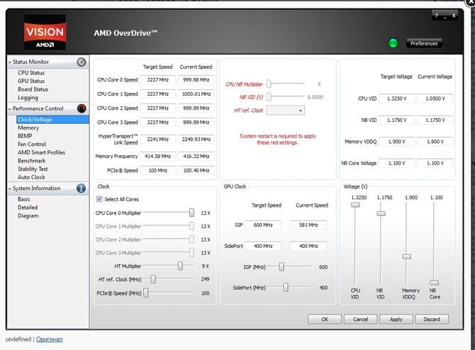
Among many other features, you can also programmatically control rotation speed coolers.
You can run this program only on chipsets supported by AMD 770, 780G, 785G, 790FX/790GX/790X, 890FX/890G//890GX, 970, 990FX/990X, A75, A85X. 
After launching the program, click section Fan control and select the necessary characteristics fan speeds.
Another interesting program with the function of regulating the speed of coolers is Riva Tuner. First of all, owners of very hot video cards prefer to use it.
Download and install the program. In our case, this is version 2.21. 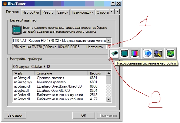
Running it, we find low-level system settings, then open the tab Cooler. The following window opens before us. 
Tick on Enable Low Level Control cooler Creating a preset fan speed, indicating the desired value as a percentage. Let's create several presets. 
Create a task depending on when you want to reduce the fan speed, that is, by adjusting schedule, range temperatures and others characteristics.


This way you can achieve a fine settings cooler speeds depending on changes in temperature of the system unit components.