In this tutorial we'll look at the basic principles of setting up interior lights and creating a global illumination effect in Mental Ray. We'll also look at some problems that can arise when lighting a textured scene, and how to solve them.
To complete this tutorial, we will first need to create a room.
In the projection window Top create a spline Rectangle. Select it and go to the tab Modify command panel. Select a modifier from the list of modifiers Edit Spline. In a scroll Selection click on the button Spline(the red curve is like this), and then in the scroll Geometry click on the button Outline and in the window Top move the spline outward a little. Now again from the list of modifiers select Extrude and extrude a three-dimensional object of suitable height from the spline. These will be the walls.
Now make a floor and ceiling from a regular plane.
Next we will cut out the window. Create Box. Position it in the wall so that all corners stick out from the wall. Select it and in the category drop-down list Geometry tabs Create command bar select line Compound Objects. Click the button Boolean, then, in the scroll that appears, click on the button Pick Operand B. Select a wall object in any window. Set the type operations B-A. The window is ready, as is the stage itself. Although no! Add a couple more objects to the room for beauty. It will be something like furniture. Apply regular standard gray material to the walls, ceiling and everything else.
Place your camera indoors and focus it properly.
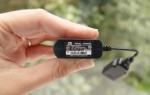
Point a light source out the window mr Area Spot.

Set up the light source. When working with photons, the parameter is of great importance Hotspot in a scroll Spotlights Parameters light source. These parameters must be adjusted as accurately as possible to the size of the window through which light enters the room in order to avoid the loss of photons, the maximum number of which depends on the size of your PC’s RAM. Since the window is rectangular in shape, it means you need to specify the shape Rectangle and adjust the cone to the size of the window. To make it easier to change the direction and cone, switch in one of the windows to the view from the light source. In a scroll Area Light Parameters check the box On and specify the type of ambient light Disc with a dispersion radius of 40. Although, you can set a much larger value. I have never observed a sharp outline of a window opening in the shadow when no sunlight enters the window. From this we can draw conclusions. If you want the sun's rays to shine through a window in your scene, setting blurry shadows would be a big mistake. The situation is different when the light is from heaven.
With the creation of the scene everything seems to be done. Send the scene to miscalculation. It's dark isn't it? It's time to figure out global illumination in Mental Ray. Opening the window Render Scene, select as visualizer mental ray. Go to the tab Indirect illumination and in the scroll Caustic and Global illumination in the GI block, check the box Enable. Visualize the scene. Almost nothing has changed. You can't do without fine tuning.
So, let's start setting up the lighting of our test scene. Set value Maximum Sampling Radius equal 4 . The Radius value is the photon search radius. It is the search radius for photons, not the size of the photon! Photons from the point of view computer graphics have no size. The absence of the Radius checkbox means that the photon search radius is approximately 110 parts of the scene. Maximum Num value. Photons is the number of samples to calculate the illumination of a point. Meaning Average GI Photons set equal 10 000 . As you already understand, the GI Photons value determines the number of photons of light sources; it is this number of photons that is stored in the photon map. The Decay value determines the attenuation with distance, a physically correct value of 2 is considered. The Global Energy Multiplier value is a kind of regulator with which you can control the overall illumination of the scene.

The Trace Depth value sets the level of reflection and refraction of surfaces in the scene. Photon Map—installation of a photon map. Please note that some resulting parameter values may differ depending on the coordinate system. This applies to all parameters that specify dimensions, distances, radius, etc. We consider all values in Inches, and not in millimeters or meters, etc.
Visualize the scene again.

Bright spots of light with a radius of 4 indicate that photons are being generated, that the photon search radius is 4 inches, and the presence of large unlit black areas in the scene indicates that there are not enough photons for the given scene. We change the number of photons from 10,000 to 500,000.

It's getting better, but it's still dark and noisy. There are two ways to get rid of noise and make the lighting more intense. To reduce noise, you can further increase the Average GI Photons value, but this will increase rendering time, and you will not achieve excellent results. Average GI Photons values are limited by PC memory capacity and you will not be able to use very large values. The second option is to increase the photon search radius, which will lead to a smoother picture. But then the secondary shadows will be calculated ugly, which will not look natural at all. The best option is to adjust these values so that there is no noise and the shadows are normal. Now that's a good image.

Here I used Average GI Photons = 1,500,000, Maximum Sampling Radius = 13, and Global Energy Multiplier = 6500. In fact, the picture is still terrible. Highlights appeared due to the Multiplier value being too high. This can often be seen in galleries, when interior images highlight window sills, window frames and, sometimes, ceilings. It is not right!
Despite the fact that the photon map method gives the most physically accurate results of scene lighting, the number of photons to obtain high-quality lighting with a minimum photon search radius should be too large. Modern PCs and 32-bit operating system will not allow you to calculate such a number of photons.
The most realistic, competent lighting in interiors is provided by the combined use of photons and Final Gather. What does it represent Final Gather? A hemisphere of unit radius is constructed above the point and rays are emitted through the surface of the hemisphere in random directions. The more such rays, the more accurate the calculation and the less noise. In practice, the number of rays is the number of samples in Final Gather. For each ray, the intersection with the nearest surface is found. The beam is processed. No further ray tracing is performed. Final Gather's ray tracing depth is always one. I recommend using only one Final Gather in scenes using HDRI maps in global environments or exteriors.
And so we turn it on Final Gather and set the values as in the figure. But first return the values Average GI Photons = 10000.

Checkbox Preview serves for quick rendering in low quality. Visualize the scene.

As you can see, there is noise, but not as much as when Final Gather is disabled. It is enough to increase the value Average GI Photons before 200000 And Samples in Final Gather with 50 on 500 , and you get a very acceptable picture.

Apply textures. I used standard materials and Max bitmaps (*. jpg). Visualize the scene again.

Not a very pleasant sight? Here! Now is the time to talk about the problems that can arise when using Mental Ray GI. As you have already noticed, in the scene there is quite a strong transfer of color from the walls and floor to the ceiling, and indeed to each other. This effect is called. You can fight this in different ways. For example, controlling color bleeding using photon shaders. But I think the following is the best option. We calculate the photon map and Final Gather in the scene with gray material, as in Figure 9, and save it to a file. Next, we assign the necessary materials to the scene objects and render by loading photons and Final Gather from the file. To be honest, I don’t understand why the developers didn’t make the color bleeding option as, for example, in the finalRender renderer.
Let's see it through to the end. Here is a picture rendered using this method.

For the sake of example, I threw a couple of models of chairs with a carpet and one wall into the scene. I am not an interior designer and this is not a competition entry, so please do not criticize me for such an incomprehensible attempt at arranging furniture.

A good picture without glare on the window and with uniform lighting and only one light source. Some might argue that the stage is a bit dark. Stop! Where have you seen a well-lit room in reality through such a small window? Don't overdo it with the light intensity. This is where overexposure appears and the scene looks unrealistic. A well-lit scene is when it is not bright and without flare, when all objects and angles in the camera’s field of view are clearly visible. To properly illuminate the scene, use the SkyLight light source.
Finally, I want to give some tips that will help you avoid mistakes in your work with Mental Ray.
1. Never make walls, floors and ceilings with zero thickness! Mental Ray will simply ignore rotated wall normals and let light into the room as if it were an open space. This is also true for other visualizers.
2. Use SkyLight for illumination. To add illumination, realism and highlight window openings located in the shadow area, SkyLight is best suited. In large interiors with many windows, instead of a skylight in window openings, you can use a photometric light source - TargetArea.
3. I recommend using only “native” materials in all external visualizers. This applies to Mental Ray to a lesser extent because both standard and tracer and architectural materials work quite well in Mental Ray. But, despite this, only the use of “native” materials, which include DGS material, mental ray, Glass (physics_phen) and Lume shaders, gives the most physically accurate and correct results. When using (in interior scenes using photon maps) mental ray material in the Photon slot, you must use a photon shader. When used in the Surface slot - DGS materiala, in the Photon slot it is better to use DGS material Photon. When using Lume shaders in the Surface slot, for example, Metal(lume) in the Photon slot, it is better to use Photon Basic.
4. Photon rendering, Final Gather and rendering progress can be monitored visually by turning on the Mental Ray Message Window.
5. Adjust the lighting in the scene by assigning a gray material to all objects. Remember that textures and materials tend to hide GI imperfections. And only after you find the optimal GI settings in the scene, assign materials to objects, adjusting the materials to the lighting, and not vice versa. Remember also that in Mental Ray, photon shaders have a direct effect on the lighting in the scene and if you want them not to affect the overall lighting set up in a scene with a gray material, set the photon shaders to the same parameters as they were when setting up lighting in a scene. Now let's talk about radii in Final Gather. Max Radius is the distance between points for which GI (global illumination) is calculated. The smaller the distance between the points, the more accurate the calculation and the more time it will take. Min Radius is the distance used in illuminance interpolations and extrapolations of intermediate points. In practice, to obtain normal quality, GI Min Radius should be 10 times less than Max Radius. Increasing the radius values leads to a decrease in the quality of secondary shadows, while decreasing them leads to more accurate rendering of GI and, as a result, an increase in rendering time. The smaller the radii, the greater the number of samples you have to set in Final Gather. The number of samples required for anti-aliasing with the above radius values ranges from 500 to 3000 depending on the scene. The bigger, the better. But you shouldn’t get too carried away with increasing this value, since the rendering time will increase significantly.
I want to start a series of tutorials on lighting in mental ray. This lesson is devoted to Final Gather, settings for the indirect lighting calculation algorithm, light sources, luminous materials and HDRI maps. The purpose of the lesson is not to create a specific scene, but to consider the general provisions and settings of secondary lighting; all scenes used are of a test nature and have the task of emphasizing a certain effect, usually to the detriment of appearance. The lesson is designed for max 2008 and higher and has example scenes for downloading.
Introduction
First, some necessary information
In mental ray, lighting, according to the calculation algorithm, can be divided into 4 parts:
1. direct tracing (scanline + ray trace).
2. Photon-Based Indirect Illumination (GI + Caustics)
3. Simplified indirect lighting (Final Gather)
4. Lighting in volumes (ray marching).
Note: I do not claim the correctness of the Russian-language interpretation of the terms, since there are many variants of translations of help and lessons and I did not intend to take them as a basis. Often GI and caustics are separated, since different photon maps are used for them, and lighting in volumes is included in GI, due to the fact that it also uses photon maps, not taking into account that a completely different engine starts working and not everything is done there with photons (2 levels of calculations are used, while the second, simplified one does not use photons)
About direct lighting:
Direct lighting means illumination from the emitter of the light source to the surface of the object, after meeting the surface of the object, based on the surface shaders (Surface) and shadow shaders (Shadow), the illumination map and shadow map of the object are calculated. Additionally, shaders from the Extended Shaders group are taken into account (surface displacement, environment). In this case, part of the rays is absorbed, and part (if the object is semi-transparent, reflective) is calculated to the next object in the scene. There is no penetration of rays into the volume of the object; the glow effect (illumination, glow) is taken into account only for the diffuse properties of the object and does not apply to other objects. GI, Caustic and Volume Photon photons are not generated.
Now let's look at the render settings, which affect the quality of the rendering as a whole. These settings are valid regardless of whether GI and FG are enabled
Sampling Quality: The parameters of this group allow you to configure supersampling, designed to eliminate the effect of broken lines, stepped gradients and all artifacts arising from the aliasing effect.
To parameters Samples per Pixel — minimum and maximum set the number of rays per pixel for adaptive supersampling to work, I won’t go into how it works of this algorithm(if you wish, you can easily find theoretical information on the Internet).
In practice, the higher the value, the better, but rendering time increases almost in proportion to the increase in values, so for scene preview it is advisable to set low values (but the maximum value should be at least 2), and increase it for the final calculation.
Parameter group Contrast , regulates the decision-making algorithm used to calculate the minimum or maximum value of Samples per Pixel, values are set from 0.004 (1/256) to 1 and in increments of 0.004 - the smaller the better, but it also affects the rendering speed.
Filter - the simplest and most quick filter- box, and the best and “slow” is mitchel.
Below parameters Rendering Algorithms — of which the most necessary is the tracing depth Trace Depth

Reflection— the maximum number of reflections of a photon, after which it disappears
Regraction- the same for transparency and the value of the maximum amount of effects - max. depth.
Simply put, if you place two mirrors on the stage, “facing” each other and a camera looking between the mirrors, you will get the depth of “infinity” of reflections according to the established parameters.
The main practical meaning of these settings is that during the creation of the scene, set low parameters for fast rendering, and at the final stage increase them to acceptable sizes.
Sources of light:
In mental ray, light sources are divided into:
- standard
the intensity of light from which decreases in direct proportion to distance and is not physically accurate
- improved standard
(postscript mr), from which the shadows are calculated, using an improved algorithm and it is softer.
- photometric
The intensity of light is specified in physical quantities and the attenuation of light is also considered physically correct. The use of photometrics is relevant when the scene scales comply with metric values.
Part One Final Gather
Final Gather — a simplified algorithm for calculating indirect lighting, consists in the fact that from each point of collision of a photon with a surface, rays are randomly emitted that intersect with neighboring objects in the scene (but only once). As a result, FG gives a simplified view of indirect illumination, due to a single reflection of light, but is much faster than a full-fledged GI, and gives a very real picture. With GI enabled (FG+GI), the calculation algorithm changes and the calculation occurs as completely as possible in mental ray, but of course, time...
So let's look at what can be achieved using FG:
First, let's enable the FG algorithm - Rendering > Render... (F10) > Indirect Illumination > check Enable FG
The main settings for adjusting the FG quality are the step with which reference points are placed to calculate secondary lighting - the Initial FG Point Density parameter - the smaller the step, the better the picture will be, and the Rays per FG Point parameter is the number of rays emitted from one point, than the more the better.

The MR developers have made several ready-made profiles that can be selected from the “Preset” drop-down list; you can select from Draft ( low quality, fast render), for viewing scenes in the process of creation, and to believe high - for the final calculations.
Let's start testing FG with an interior scene.
I made a simple scene showing a room with a window and a few lamps. The colors of the walls, ceiling and floor are specially gray - it turned out gloomy, but the lighting effects will be better visible this way
This is what the room looks like without FG turned on, with a temporary light source (after FG is turned on it will be removed)

On the left are two lamps that are not full-fledged light sources, but their material is represented by a mental ray material, the Glow(lume) shader is assigned as the surface:

the glow color (Glow) and diffuse (diffuse) are pale yellow, the surface material is represented by a glass shader (Glass(lume)) whose settings are left at default. The brightness of the glow (Brightness) is also left at default = 3.
These lamps will act as dim, filling lighting for the room.
On the right are two recessed mr Area Spot light sources. - default settings, that is, they have not been changed, they will illuminate glass and metal balls.
All stage materials (except for the described left lamps) are Arch & Design type materials, by selecting which you can quickly get settings for a specific surface from the list of predefined ones:

walls made of rough concrete (Rough Concrete), ceiling made of polished concrete, floor - Glossy Plastic, window - Glass (Thin Geom), with a Checker map applied for transparency.
As a result, we should get a gloomy room, night outside, weak general lighting, and separately illuminated balls.
Click render:

the result is clearly unsatisfactory - the lighting is too dim. You can increase the value of Multiplier, light sources and Glow for the left lamps, but if increasing the intensity of the light sources is still acceptable, then increasing the Glow value will lead to “distorted” lighting - the areas around the lamps will be very bright, and the floor will remain black.
Output in exposure adjustment
Go to the environment settings - Rendering - Environment (button 8) - Exposure Control section and select the exposure type, I left the logarithmic type. But the Mental Ray developers recommend using a photographic exposure controller, especially when working with photometric light sources.

now render again:

It’s already better, but the noise in the illuminated areas from the left lamps has become more visible - this is exactly the effect of setting the FG settings to low (the “Low” profile is set). The question arises - how to calculate the golden mean between rendering speed and quality. Naturally, by installing Very High, we will get a good image, but we will wait a very long time for the result. The render itself can help us with this; let’s ask it to display the FG anchor points for us:
go to the Processing tab (Rendering - Render...)
section “Diagnostics”, check the Enable box and indicate what we want to look at FG:

render again:

distance between green dots in illuminated areas, should be minimal, this is achieved by reducing the step of the reference points, ideally the filling should be continuous, after which further reducing the step will only lead to an increase in rendering time, with a minimal increase in quality. Sometimes noise may occur on surfaces far from the light source; increasing the emitted rays will help here, without reducing the pitch. And don’t forget about the sampling settings, which I wrote about at the very beginning.
Let's continue building the scene:
Very often there is a need to depict some light-emitting objects with complex geometry - shop windows, aquariums, TV screens, which also illuminate the scene, but the task is not to detail the object, but simply to imitate it with textures. At the same time, problems arise with their lighting characteristics - with high brightness, dark objects also begin to glow, and when the brightness is reduced, the light areas do not sufficiently illuminate the surrounding objects. This injustice arises due to the fact that a 24-bit image is not able to store information about the true glow intensity of each pixel. The situation will be corrected by using them as textures HDRI maps.
How to visualize the value of HDRI cards? - imagine that you took a photo of a sea white-sand beach against the sun. Load the photo into Photoshop and use an eyedropper to look at the colors of the pixels on the solar disk and white sand, the colors of the pixels on the solar disk will usually be #FFFFFF and the color of the pixels on the white sand will be either the same or slightly darker. Now let’s lower the brightness of the entire image, for example by 50% - the sand will become darker, which is correct in principle, but the fact that the solar disk will dim is not okay, our Sun is very bright. But if you take a picture with a special camera that can save pictures in HDRI images, this will not happen, the solar disk will remain bright, as if we simply lowered the sensitivity of the camera.
Let's try to use an HDRI map in our scene. I didn’t find a ready-made map that would depict some kind of luminous object, so to test the effect, I simply made an hdr file in Photoshop with a gradient fill - in the middle there is a bright blue line that loses brightness towards the edges. (You can make hdr yourself by selecting 32-bit image mode in Photoshop).
We open the resulting map in Max as a regular Bitmap, an image conversion dialog appears:

The main attention should be paid to the conversion option in the “Internal Storage” section, by default Max suggests discarding the brightness information and simply marking bright and dark places with certain colors - 16 bit/chan mode, this will not suit us, so let’s set the Real Pixels mode and click OK .
I used the selected map for a material similar to the material of the lamps, with the glow parameter, and applied it to the parallelepiped near the far wall
For comparison, two renderings:
the first one is a card in 16 bit mode:

due to the replacement of bright areas with white, the illumination from bright areas occurs with almost white light
the second one is real:

there is clearly a difference.
Using Photoshop, you can make an approximate analogue of hdr images from ordinary photos; to do this, you need to convert the work to 32-bit color, make a copy of the image, increase the brightness on the copy using a histogram (the brightness as such cannot be changed there) and overlay both images with the Multiply parameter (multiplier).
Here is a scene where the TV picture is obtained in exactly this way:

This scene contains three photometric light sources simulating 60-watt incandescent lamps.
Let's look at them in more detail.
Photometric light sources are needed to simulate real light sources in their physical parameters, but certain conditions are required
Use the metric system of measurement when creating a scene
Respect the actual sizes of objects on the stage
The indirect lighting algorithm FG or GI must be enabled, or better yet both
The main characteristics of photometric sources are the emitter temperature, which gives the color of the light stream, and the power of the light source.
Since we are used to measuring power in watts, and we have only a superficial idea of the temperature of the source, I will give a table of the most common household light bulbs
|
Power |
Temperature in K |
|
|
12 volt - display lighting, less often table lamps |
||
|
Household incandescent lamps 220 volts |
||
|
Fluorescent lamps |
||
|
As such, they do not have a temperature, and are divided according to the color of the limuniphor: Cold white 4500k, Daytime white 6500k, Warm white 3000k |
||
|
Arc mercury\sodium |
||
|
The temperature is 6500 - 11000K, but as a rule, it is necessary to apply a filter, for example, sodium ions color the light red, and the inert gases present add a blue-green spectrum. |
||
Now let's talk about sunlight.
The developers of the mentality divided sunlight into direct light from the solar disk - bright with strongly pronounced shadows - mr Sun and filling from the cloud cover and atmosphere with strongly blurred shadows - mr Sky.
When you add the mr Sky light source to the scene, you will be automatically prompted to add the mr Physical Sky shader to the environment, which is advisable to agree with.

in the settings you need to specify the color of the sky at night “Night Color”, with low brightness values - multiplier the color of the sky will tend to this color.
Adjust the height of the horizon and the color of the earth's surface, add haze (Haze) and the parameters of the ratio of red and blue colors in the sky (evening\day) in the Non - Physical Tuning section:

mr San settings also have options for adjusting the horizon, brightness and color, haze, and also added an option for adjusting shadows - Softness - shadow softness and quality at the boundaries of soft shadows: Softness Samples.
sample test room scenes
with the sun outside the window

and in cloudy weather

I forced the light intensity up so that I could see the light filling the room and the shadows on the floor. In the first case, the rays are straight and almost parallel - a spot on the floor is illuminated and, secondarily, a reflection from the floor, a spot in the window area is illuminated. And in the second case, almost the entire room is illuminated. When rendering both scenes, FG was configured to the Low profile, which caused loud noise on illuminated areas.
Often, when depicting rooms where light comes from a window, it is desirable to add a Volume Light effect to the light sources to enhance the effect of bright rays or the dusty atmosphere of the room. On the mr Sun light source, this effect is not applied correctly, probably due to a different principle for calculating shadows; the illuminated volume is simply filled, without taking into account the shadowed areas. Therefore, for this effect you will have to use standard sources:

Let's finish with the premises and move on to simulating external lighting
If we have an hdr map that simulates the sky, then we can easily apply it to our scene. This is done by applying the map to the Skylight light source. The light source itself can be placed anywhere in the scene - this is not important, the main thing is that FG is turned on, otherwise it will not work.
Click on the button that says None (there is no map by default) and select our hdr image (as I described above), or specify a slot from the material editor where such a map is already open.
Here is an example of a scene where a small building is depicted, surrounded by a moonlit night. The environment map is applied not only to the light source but also to the Environment map slot.

we see soft lighting from the sky throughout the scene, as well as pronounced shadows from the moon.
And now here's the fly in the ointment:
For the picture shown above, I specifically used a dark map with a bright spot of the moon, which I further processed in Photoshop to increase the brightness of the moon and darken the sky, otherwise the effect of the map would not be noticeable. In fact, in MR, in my opinion, the algorithm for taking into account the brightness components of the map for the Skylight source does not work quite correctly.
I will give examples of comparing scenes for MR and V-Ray.


in both cases multiplier = 3 I did not change the other parameters of the card, I tried to use materials with similar properties.
As you can see, in the second case the picture is “tastier.” The only thing I want to note about Vi_rey is that you need to remember that you cannot use the same card for lighting and reflection. Look carefully at the picture - where the moon is according to the reflection and where its shadow is directed - the difference is 180 degrees. There is a parameter in the settings for map rotation, but you need to remember this!
True, I took the most difficult map - the moon is not bright and small, on good maps the differences are almost invisible, but the fact of different calculations is obvious. Let everyone draw their own conclusions.
I think that's all I wanted to show in this lesson. Finally, I will highlight some small features that, in my opinion, are worthy of attention.
- Glow material. IN previous versions Incorrectly illuminated himself. If not the entire surface of the material is illuminated, but only some individual areas (a map is applied) or the material is part of a Blend material, then the luminous area will illuminate neighboring objects with another material, but objects with the same material will not illuminate itself. There is no such problem in 2008 Max. Here's an example scene:

the entire structure consists of one material based on Blend. As we can see, the material illuminates itself perfectly (there are no light sources on the stage).
- except using hdr cards, you can also use.exr cards, which are less common but also carry information about light intensity. Exr format file conversion window when assigning a card:

- While creating animations where there are bright light sources or textures based on hdri images on the stage, Motion effect Blur in all versions of Max up to and including 2008 does not work correctly, since the design of our vision (and camera matrices) is such that the brighter the spot, the brighter the “blur track” it will leave. Happy owners of Max 2009 The kit includes an HDR Image Motion Blur(mi) shader, which is placed in the “Output” slot of the camera effects, which are available in the “Renderer” render settings:

This shader allows you to blur the image of not only scene objects, but also the scene background to which the map with the image is applied.
For comparison
Blur on glowing objects in the scene

and for the background on the same card with the moon

This concludes the first part of the lesson. In the next part I will touch on the problems of GI and light in volumes.
Hi all. My name is Maxim Ganzha, today after numerous requests from my friends, I finally decided to write a short article about how I create my interiors. We'll look at one of the latest works with crazy lighting and amazing composition =), which I did in MentalRay.
"Livingroom"
Have you ever wondered why some works attract more interest on forums than others? I'll tell you a little secret. It's all about beautiful lighting and strong composition. We will talk about this, as well as many other things, in this article. =)
I think we will skip the modeling process, otherwise the article will be very long and tedious. So let's go!
1. Setting up and adjusting lighting.
In order to get started, first of all you need to open the scene and select the Mental ray render from the list of available renders.
We open the scene.

Go to render settings F10, In the "Assign renderer" tab, click the "Choose renderer" button and select Mental Ray.

After we have selected the render, Mental Ray shaders and materials will become available in the materials and maps browser. Select the "Arch & Design" Material and configure the RGB diffuse color as follows, about 0.8 0.8 0.8 and the rest of the settings in the screenshot. I would also like to note that you should not forget to include “AO” in your materials. With this setting the shadows will look more realistic. and the darkening characteristic of real light will appear in the corners. I always set “Max Distance” to about 3 meters (distance from floor to ceiling).

Open the render settings. In the "Translator Options" tab, turn on the Eneble checkbox for Material Override and throw our prepared gray material into the slot. This will ensure that all objects in the scene are painted with the same material. This will make it easier for you and your computer to adjust the lighting. The rendering will be fast and time-consuming. We will look at the materials of all objects in the scene later.

After assigning a gray material to all objects, we must create a "Daylight System"

create and place the sun; it’s okay if it shines in the other direction. go to the system settings and, as shown in the figure below, check the “Manual” box, after that we can set the sun as we please without adjusting the time and date. Place the sun as shown in the picture.

When creating a daylighting system, 3ds max will offer us to set “mrSky” as the environment, we agree and move on.

After we installed the daylighting system, we move on to the windows. You need to put “mr Sky Portal” in them; it is located next to the photometric lamps.

press the button and set it as shown in the figure below.


As you noticed, the portal is directed with an arrow in the wrong direction. We need the arrow to point into the room. To do this, simply click the Flip Light Flux Direction checkbox. And everything will fall into place as in the picture below. =)

We select our portal, hold down the "Shift" key and move it to the left to the second window. 3ds max will offer us a copy type. Select "Instance"

Finally they turned on daylighting. Now we just need to configure it. Press "F10" and turn on Final Gather (FG) Global and Illumination (GI). The settings are shown below. I also turned on the FG & GI checkboxes and reduced the quality of the FG Precision Preset.

We set the image resolution to 450 by 338 and make a test render.

Press key 8 and in the “Environment” settings in the “Exposure Control” tab set “mr Photographic Exposure Control”.

Click render and see what we got =)

The following exposure settings correspond to this render:
As you can see, nothing remarkable happened. The light is dim and ugly. In order to create beautiful lighting, we will have to tweak the exposure control a little. Then I remembered that I wanted to use artificial light. Turn on the floor lamp next to the sofa. The sun would obviously interfere with this and I turned it off. Go to the Daylighting System settings and uncheck "On" in the "mr Sun Basic Parameters" tab.

Now press the “8” key again and set up the exposure control as shown in the figure below.

And this is what we got.

Well, that's a completely different matter. The light became like daylight. =)
Now let's start setting up the floor lamp lighting. For artificial lighting, I like to use photometric lights. Choose this lamp:

And we put the light bulbs in the floor lamp in place as shown in the pictures below.


In the lamp settings, turn on the shadows "Ray Traced Shadows" In the "Shape/Area Shadows" tab, set the disk with a radius of 30 mm. Turn on the "Light Shape Visible Rendering" checkbox and set 64 samples. These settings will allow us to achieve beautiful realistic shadows from the lamp.


Let's see what happened.

We see that the light from the lamp is white. But I would like to make it more like a simple light bulb. To do this we need to lower the temperature of the light. We also see that the light is too intense. With such a shutter speed of the camera and such daylight, it should practically not be visible. and he is like a spotlight for us. =)
Open the settings of the photometric lamp again and adjust the temperature with intensity.

Let's see what happened:


That's what we need. Perfect light! I don't know about you, but I really like it. And for whom is the play of orange light with blue a win-win option in architectural visualization? =)
I would like to add some special effects. To do this, go to the render settings, and in the "Camera Effects" tab, turn on the "Output" checkbox. DefaultOutputShader (Glare), take the shader with the mouse and throw it into the "Material Editor", after which 3ds max will offer us the copy type. We check "Instance" and click " ok".

Behind the windows, as in the figure below, we place a “plan” object, which will play the role of a background.

In the settings of the “plan” object, turn off the checkboxes as follows.

And assign it the material "Arch & Design"

Once again we press the render button and see what we got. =) For quick calculation, I assigned a gray material to all objects except the background.

Well, we got a good picture. A slight haze from the glow effect gives the picture a lively atmosphere. You can stop with the render settings and start looking at the materials.
2. Setting up materials.
It's time to look at the most basic materials that I used in this scene. Let's start with the most interesting thing.
Carpet.
As you can see from the mesh, the geometry is very simple.

The carpet used simple "Arch & Design" material with the following parameters:
Diffuse map.


The following texture was used in "Displacement".


Sofa.
The sofa mesh is quite complex. On this model I used two materials. Fabric and wood on legs.

Let's look at the fabric material first.

We throw the “Ambient/Reflective Occlussion” shader into the diffuse slot and place two fabric textures of the same type in it. The only difference is that one is darker than the other. The settings are in the picture below.

The following parameters are ambient occluded and bump.

now wooden legs.

In diffuse I used simple map parquet The settings are in the picture below.

bump settings.

Coffee table.
The material and mesh of the coffee table are as follows.


with glass everything is simple, select the material “Arch & Design” and select the finished material from it as shown in the figure below.

Magazines.
I wanted to make “Arch & Design” a glossy magazine, I didn’t really bother with the material settings. Therefore, I used simple glossy plastic.

log grid.

the settings look like this.

I colored the pages with the same material only with white in Diffuse color.
Newspaper girl.
The newspaper rack itself is made of varnished wood. I decided to paint it with "ProMaterials" Hardwood.

Newspaper grid.

Promaterial Hardwood settings.

I also used a second material to paint the newspapers themselves and made it matte.

newspaper material settings.

Flower.
On at this stage I used the same, my favorite material "Arch & Design". 

You can see the settings in the pictures below.


Curtains.
I had to experiment a little with the curtains. And finally I came to this option.

Mesh curtains.

In the diffuse as shown in the picture below, I naturally used the texture of the fabric. Also, don’t forget about the AO parameter. =)


Walls.
I wanted the walls to be made from old plaster, which was later painted. And this is what I got, my favorite “Arch & Design” again.

On the wall the map looks like this.

The reflection settings look like this: 

Parquet material (floor covering).

Settings.


Floor lamp.
I used three materials on the floor lamp. These are a lampshade (material is fabric), a stand (material is metal) and an electrical wire (material is plastic).

Let's start with my favorite material "Arch & Design" - this is the fabric on the lampshade of the floor lamp.

It's pretty simple. Diffuse color, slight transparency and bump. We will see this in the settings in the pictures below.


To make the metal stand material I used ProMaterials: Metal.


Floor lamp plastic wiring material ProMaterials: Plastic/Vinyl


I would also like to recommend you one resource that is directly related to Mental Ray materials. He helped me more than once. Thanks to those who founded the site. http://www.mrmaterials.com/
That's probably all, we're done with the materials. Now we can discuss composition.
3. Final render settings.
It's time to increase the render settings and make the final render. In the picture below you can see the settings.


Turn on the render and wait =)
4. Composition.
There are 10 rules of composition that are worth learning.
1. Contrast.

ms_Dessi
How to attract the viewer's attention to your render? There must be contrast in the frame: a lighter subject is photographed against a dark background, and a dark one against a light one.
2. Accommodation.

Morro
Important plot elements should not be placed randomly. It is better that they form simple geometric shapes.
3. Balance.
Objects located in different parts of the frame must match each other in volume, size and tone.
4. Golden ratio.

The golden ratio was known back in ancient Egypt, its properties were studied by Euclid and Leonardo da Vinci. The simplest description of the golden ratio is that the best point to position your subject is approximately 1/3 of the horizontal or vertical edge of the frame. The placement of important objects at these visual points looks natural and attracts the viewer's attention.
5. Diagonals.

FeodorIvaneev

FeodorIvaneev
One of the most effective compositional techniques is diagonal composition. Its essence is very simple: we place the main objects of the frame along the diagonal of the frame. For example, from the top left corner of the frame to the bottom right. This technique is good because such a composition continuously leads the viewer’s eye through the entire picture.
6. Frame format.

Morro

FeodorIvaneev
If the rendering is dominated by vertical objects, use the vertical frame format. If the objects are horizontal, take horizontal shots.
7. Shooting point.

FeodorIvaneev
The choice of shooting point directly affects the emotional perception of the photo. Let's remember a few simple rules: For character rendering, the best point is at eye level. For a full-length portrait - at waist level. Try to frame the frame so that the horizon line does not divide the photo in half. Otherwise, it will be difficult for the viewer to focus on the objects in the frame. Adjust the camera angle at the level of the subject, otherwise you risk getting distorted proportions. If you look at an object from above, it appears smaller than it actually is. So, when drawing a character from the top point, you will get a short character in the render.

Dmitry Schuka
Our brain is accustomed to reading from left to right, and we evaluate a photograph in the same way. Therefore, it is better to place the semantic center on the right side of the frame. Thus, the gaze and the subject of shooting seem to move towards each other. When building a composition, always take this point into account.
9. Color spot.

If there is a spot of color in one part of the frame, then there should be something in another that will attract the viewer's attention. This could be a different spot of color or, for example, an action in the frame.
10. Movement in the frame.

Alexander1
If you decide to draw a moving subject (car, cyclist), always leave some free space in front of the subject. Simply put, position the subject as if it had just “entered” the frame, rather than “exiting” it.
Let's stop at the composition and start post-processing the render.
5. Post processing.
Now it's time to do a little post-processing on the resulting image. I usually always resort to this in my daily work. Since some things are still easier to achieve in Photoshop than by means of rendering. So what do we have =)

If you look closely, the capabilities of Mental Ray are very wide; the picture requires practically no effects. But it's still worth adding a few lens effects. To give the feeling of a real photograph.
It seemed to me that the picture lacks a blue glow effect around the windows, so we open our render in the excellent Fusion program and apply the glow effect to the existing image. In common parlance, we attach the “SoftGlow” node to it

click polygon and outline the window as shown in the figure below. Thus, we drew a mask in fusion on which the glow effect will be applied.


Now click on the SoftGlow node and configure it as follows.

we will have a pleasant glow near the windows.

add the SoftGlow node again and apply the effect to the entire picture. Set it up as follows so that the entire picture has a slight blue glow.

turn off the Red, Green and Alpha checkboxes and move the Gain slider a little to the right. The picture below shows both options. Left before, right after applying the effect.


Close Fusion and open the image in Photoshop.

in photoshop we open the image with the Magic Bullet Photo Looks plugin... and apply the Anamorphic Flare effect with the following settings

a very beautiful glow characteristic of a real camera appeared. Next, apply the Vignette effect and add a slight darkening along the edge of the picture, the settings are also shown in the lower right corner.

Let's add a very interesting effect called Shutter Streak, which adds small rays from the bottom and top of our picture.

now my favorite step =)
Add the Chromatic Aberration effect and configure it as shown in the picture below.

with a high resolution picture it will almost not be visible, but it will still add realism to the picture.
Press the button

and save the image.
Here's what I got.

So my lesson has come to an end, I want to wish you all good luck and fast renders. Always yours Maxim Ganzha.
Lesson taken from 3dmaks.com
Lesson taken from the site RENDER.RU
I continue the topic of lighting in Mental Ray. In this lesson I want to talk about simulating artificial light sources to illuminate rooms. Photometric light sources will be used, which 3D MAX 2009 puts at our disposal. Photometric exposure control will also be considered.
It is assumed that those reading this lesson are familiar with the lesson on indirect lighting: posted earlier.
Let's get started
When choosing any photometric light source, Max insistently suggests turning on photometric exposure control, so I’ll start the lesson with a description of this type of exposure.
Exposure control:
After creating a light source based on its physical characteristics (brightness, color, ...), it is assumed that illuminating the scene with it is the most correct and we can only globally change the brightness of the image (render) using exposure control.
Photometric exposure control is done in MR by analogy with the operation of a camera.
Answering yes to the warning when creating a photometric for the first time:
we agree to the inclusion of appropriate exposure.
The exposure control menu is accessed from the main menu:

or through the “Environment” item (key 8).

in the mr Photographic Exposure Control rollout you are prompted to select preset exposure parameters:

for the exterior scene (day/night) and interior (day/night) scene, but they are usually very rough and it is still better and more correct to configure manually:
Those who use cameras know that the main parameters (for lighting) when shooting are film sensitivity / matrix (ISO), aperture and shutter speed (shutter speed). The brightness of the image depends on the settings of these parameters.
For example, photographs in which there is desk lamp with a light bulb with the following parameters:
that is, the brightness is 370 lm, and the color of the light flow is 4500-5000K (halogen)
Due to the setting of different shutter speeds, the brightness of the image is different. Similarly, in MR, by setting different exposure parameters, we change the brightness of the rendered image, without changing the parameters of the light sources .
For example, I made a very simple scene where there is a light source with the same physical parameters as in the photo, and only the exposure speed changes:
|
|
|
|
|
|


Options:
Shutter speed- this is the shutter speed or shutter speed, the value by which 1 second is divided - the higher the set value, the darker the photo
Aperture- aperture size - the larger, the brighter the picture
Film speed- film sensitivity - the higher, the more sensitive the film is to light and the brighter the picture.
In 3d MAX it is not necessary to edit all three parameters; a parameter is created based on them Exposure Value which is used by the renderer, so it is enough to either set EV, or, as I usually do, set only the shutter speed.
Below the exposure parameters are the image processing parameters, similar to those in digital cameras or similar to the use of film filters. - gamma, adaptation to the type of light sources.
Actually, there is nothing complicated in using exposure, the main thing to remember is that you should not change the intensity of the light sources, thereby introducing an imbalance into the scene - just adjust the exposure for a darker/lighter image in the render.
Now, actually, the light sources
When creating an artificial light source, the editor divides them into targeted and free:

no matter what source is created, you can make it either targeted or free at any time by checking the target checkbox in the main source parameters tab.

From my own experience, I can advise you to first create a targeted source, for the convenience of its location on the stage, and then turn off the target, so that later there will be no problems with the orientation of the emitter in sources other than point ones.
To correctly calculate shadows, it is proposed to use “Ray Traced Shadows”, which are created taking into account the characteristics of the object’s material.

Depending on the requirements of the scene or the effects being created, you can use Shadow Maps, which are calculated faster, but do not take into account all the characteristics of the materials.
Examples of shadows:
Traced shadows:

shadow map with default settings:

As you can see, the transparent material is not taken into account, the shadows are created based on the object mesh. The quality of the shadow depends on the quality of the creation of the shadow map and is configured in the “Shadow Map Params” rollout of the light source settings. For example, by increasing the map size or sampling quality, you can achieve sharper shadows.


Since the lesson is aimed at creating artificial light sources for the interior, I will not dwell in more detail on creating a shadow map, since in interiors (my opinion) it is more relevant to use traced shadows.
As for traced shadows - sometimes when using glass like Thin Geometry, Glass (lume), some artifacts appear on the object, in the form of separate spots (look at the first picture with traced shadows - the right cube has spots on the inner shadow). There is no use in improving the sampling parameters in rendering. You need to enable the two-sided shadows option in the light source settings:


Photometric Web- a light source, the configuration and intensity of which is calculated based on the “photometric web,” most accurately conveys the light parameters and saves a lot of time when creating scene illumination.
Spotlight- a light source of the “spotlight” type is usually used for global illumination of the scene; its use in interior solutions is irrelevant (again, my opinion), except for simulating projectors or special effects.
Uniform Diffuse- a light source illuminating in the direction from the emitter to the target.
Uniform Spherical- a light source that illuminates in all directions from the emitter.
Uniform Diffuse and Uniform Spherical
The settings for these types of sources are identical; with their help, you can simulate almost any light source well - fluorescent lamps, light bulbs and ceiling panels:
In the settings you are prompted to select the emitter type:

and if the emitter is different from the point one, it will be possible to include it in the rendering process

Let's look at some of the nuances of creating specific light sources:
Fluorescent lamps:
When creating a fluorescent lamp, its intensity based on the entered data will be calculated as from a conventional light source, but for fluorescent lamps (especially older models), the light distribution will be visually slightly different. Due to the fact that the luminescent layer is irradiated by ions with a certain frequency (and in old lamps with a frequency of 50 hertz) and due to the peculiarities of our vision, the light intensity will decrease faster than from a source with a filament (this applies only to the visible image, physically , over a certain period of time, the weakening of light is quite normal).
So, let's increase the attenuation:
Pre-render with normal settings:

Let’s set the attenuation to 50% (I didn’t find any information about the exact values, but using the example of the Soviet LB’eshka, testing showed exactly that)

It would seem that you can simply reduce the brightness at the source, but when using ready-made source profiles from IES, it is more convenient and the calculations are more correct:

Incandescent lamps:
Incandescent lamps also have an additional effect of changing light with distance, but it is expressed in a shift of the source spectrum to the red region:
To enable this effect, you just need to check the box:

for example, I slightly increased the attenuation value to have a more visual effect:
preliminary render with a light temperature source of 4000K:

and attenuation is enabled:

examples of scenes using these source types
In this scene, the emitters are not involved in the rendering process, but the highlights on the surfaces still correctly account for the presence of sources:

in the second scene of an object like “public MeZho”, the sources are visualized and imitate the surface of lamps:

Photometric Web
In the real world, the flow of light from lamps is extremely rarely uniform, due to the fact that the lamp bulb itself is a lens, and, as a rule, the flow is changed by reflectors and additional optics in the lamp.
For example, here is a photo of the first light source I came across at lunch:

to create such a picture of the light flux, you need additional constructions near the source, or drawing a map for the “Projector Map”, which requires additional time and distracts from the creative process.
They will simplify the procedure for creating light sources, using the type Photometric Web:
When choosing of this type In the source settings, a scroll will appear to select a settings map:

By clicking on the file selection button, a dialog for selecting a map will open:

The “IES information” section provides a diagram of the propagation of light on the “web” and information about the light source.
IES files can be downloaded from the Internet; as a rule, lighting equipment manufacturers present such maps, or you can find interior design archives. There are also IES generators with which you can create your own sources.
After applying the IES map, the light source icon takes on the source configuration:
in the Photometric Web settings there are parameters for rotation along three axes; these settings are relevant when the source is different from a point source. If the source is, for example, linear, and the card has a complex configuration, then the method of positioning the card becomes relevant:

In the figure at the right source, the map is rotated 90 degrees in Z.
Here is an example of applying a map to a point light source to simulate a lamp

Once upon a time, during 3D Max 6.0, I had a problem with simulating road lighting with car headlights. Then using IES would save me a lot of time.

With the help of IES's juice you can simulate not only individual light sources, but also groups of sources; in fact, this is their widest application.
For example, ceiling lights consist of several fluorescent lamps and are additionally divided into several cells by reflectors. To simulate such a light panel, it is enough to create one light source and apply it to it the desired card. The description of the card describes in sufficient detail the parameters of the light and what generates it. IES files can be opened with Notepad.
For example info:
IESNA:LM-63-1995/GPA22-3t
Photopia 1.10 PHOTOMETRIC REPORT
L.A. LIGHTING MFG. CO.
GPA520-3-2TH-S9
2X2, 3-LAMP, T-BAR, 9 CELL PARABOLIC.
FO17/31K
17 WATTS T8 FLUORESCENT LAMP
indicates that a panel of 3 is being simulated fluorescent lamps, with a power of 17 watts, enclosed in 9 parabolic cells.
An example of simulating LSD lamps with two separated lamps:

On the wall you can clearly see the darkening under the light source, which gives rise to a stiffening rib between two lamps as part of the entire lamp.
Well, that's all I wanted to tell you about simulating artificial light. Perhaps I missed something, because I write about those things that I use in my work and what is relevant in my opinion.
Interior lighting system in mental ray
mental ray uses its own light sources. These sources are very diverse, but we use only those that allow us to conveniently set up soft interior lighting.
The final soft picture will be possible only after adjusting the atmosphere. We will do this later, after working on the light sources. Now our task is to consider the procedure for working with light sources used when working with interiors.
Let's consider working with them using the example of a specific interior.
1. Run the mr_svet.exe file in the Primeri_scenGiava_4 folder on the CD. This is a self-extracting archive that contains all the files needed to open the scene. After launching the file, click the " Extract". After that, run the file mr_svet.max, located at C: mr_Svet.
2. In front of you is a simple scene with an already familiar room. It contains only a table and four chairs located by the window. There is a film camera in the room. To get inside the room, you just need to turn on the camera. Select a projection window Perspective(Perspective) and press the key
3. First, let's create a common source that will allow us to add lighting to the scene. This will be the source of sunlight. It will create the effect of rays of light falling through the window. In the first section of the command panel ( Create) select the last subsection - Systems(Systems). Here we need a system creation tool Daylight(Daylight) (Fig. 4.54). Select this tool, then move the cursor to the center of the room in the projection window Top(Top view), hold down the mouse button and move the cursor to the side, creating a compass diagram. Release the mouse button and move the cursor up - thereby creating a light source.

4. As a result, a light source was added Daylight(Daylight). It needs to be configured. Select the source itself (not the compass-shaped target point) and go to its parameters in the second section of the command panel. Here we first need the scroll parameters Daylight Parameters(Daylight parameters) (Fig. 4.55).

5. Expand the list of lighting type options Sunlight(Sunlight) located at the top of the scroll. Meaning Standard(Standard) here needs to be replaced with Mr Sun(Sun).
6. At the bottom of the scroll you need to replace the value Standard(Standard) parameter Skylight(Sky light) on Mr Sky(Sky). Answer “Yes” to the question that appears.
7. Also in this scroll you need to select the item Manual(Manual) in the parameter group Position(Position). This will allow you to manually change the position of the light source in space. Otherwise, its position could be set by setting the date, time and interior location. In our case, it will be more convenient to move the light source manually. After setting all of the above parameters, the scroll should look like in Fig. 4.56.

8. Now you need to correctly place the source in relation to the room. It is necessary that the rays of light fall obliquely through the window. To do this, select a light source and place it in relation to the room approximately as shown in Fig. 4.57. You can install it at a specific point using the window for accurately entering coordinate values. Select the source, then select the motion handle, click on it right click mouse and set the following coordinate values: X = 420, Y = 600, Z = 400.

9. If you now visualize indoors, the room will remain completely black, but there will be a spot of light on the floor in the shape of a window opening. Light source Daylight(Daylight) only allows you to add light to the scene. But you can correctly distribute the light using an additional source - mr Sky Portal(Sky Light Portal). This source does not illuminate the scene itself, but only collects and directs light from the source Daylight(Daylight).
10. In the first section of the command panel ( Create) select the third subsection - Lights(Light Sources), then select an option from the object type drop-down menu Photometric(Photometric). Here we have a source creation tool mr Sky Portal(Sky Light Portal) (Fig. 4.58).

11. Source mr Sky Portal(Sky Light Portal) has the shape of a plane, from which light is emitted in one direction. Select this tool, then in the projection window Top(Top view) create this source (by stretching its diagonal).
12. Go to the settings of the newly created source. Here we need scroll parameters mr Sky Portal Parameters(Sky light portal parameters) (Fig. 4.59). In Group Dimensions(Measurements) set the following values: Length(Length) - 200 cm, Width(Width) - 200 cm. Thus, you have made a square-shaped source with an area of 4 square meters.

13. The source must be placed indoors, so that it is located directly above the ceiling. In the projection window Front(Front view) Move the source up to the ceiling. You can also place it at the desired point using the window for precisely entering coordinate values. Set the position of the source to X = 250, Y = 200, Z = 260. The source is installed at the required point, but it may be directed in the wrong direction. We need it to shine down into the room. The direction of light is indicated by a special arrow, which is clearly visible in the windows Front(Front view) and Left(Left view). If it shines upward, then in the parameters of this source, at the very bottom of the scroll mr Sky Portal Parameters(Sky Light Portal Options), check the box to the left of the caption Flip Light Flux Direction(Reverse the direction of light flow). As a result, the direction of the arrow will change. Now the source shines inward.
14. Go to the scene view through the camera and render (key - to start visualization). Now the imaging procedure takes much longer. The result is a semi-dark frame, in which the contours of the furniture can only be guessed at the moment.
15. Both required sources are installed. Now you just need to operate with the intensity values of their illumination. Select the created source mr Sky Portal(Sky Light Portal) under the ceiling, go to its parameters and increase the parameter value Multiplier(Amplifier) up to about 25 units.
16. Select the source created in step 3 Daylight(Daylight) and go to its options. Here we need to operate with parameters Multiplier(Boost) in scrolls mr Sun Basic Parameters(Basic parameters of the sun) and mr Sky Parameters(Sky parameters). Set both parameters to 3.
17. Turn on the camera to view the scene and render. There is now enough light in the room (Fig. 4.60).

Thus, we adjusted the lighting of the room using sources Daylight(Daylight) and mr Sky Portal Parameters(Sky light portal parameters). It is already obvious that light sources mental ray allow you to create much more realistic lighting than standard ones. However, the picture can be improved further. For example, by adding atmosphere.
Save the current scene. We will perform subsequent actions to add atmosphere in relation to it.
Clue.
All of the above settings and parameter values (in particular, source intensities) were applied to the 3ds Max 2010 version. In earlier versions necessary settings may vary. If you get a picture that is too bright, or vice versa, too dark, correct the light intensity yourself by working with the parameters Multiplier(Amplifier) created sources.
This text is an introductory fragment. From the author's bookCreating lighting In the library of the Landscaping and Deck Designer program, in the Electrical folder, there is a whole collection of various images that can be useful when designing a site. Garden lights are located in the Street Lamps folder, which is included in
From the author's bookCreating lighting In order for the site to be beautiful in the dark, in order to use it comfortably even at night, it is necessary to think through and include lighting fixtures in the project plan. There are enough such devices in the program library - there are external
From the author's bookLighting Model OpenGL uses the Phong lighting model, according to which the color of a point is determined by several factors: material and texture properties, the magnitude of the normal at that point, and the position of the light source and observer. For correct
From the author's bookPhotometric lighting sources The action of photometric light sources is based on the real properties of light, which makes it possible to organize physically accurate lighting. They are able to almost perfectly reproduce any real light source: from a light bulb
From the author's bookComposition and styles in interior design Creating a design is not an easy task. From an idea to a finished interior is a long and difficult path. the main task, which is carried out by the designer, is the development of the interior of the room, corresponding to the individuality of the owner, his
From the author's bookWorking with mental ray We talked earlier about what the mental ray visualizer is, as well as its features. Let me just remind you that this is a much more powerful renderer, allowing you to create more realistic images by simulating the atmosphere of the scene. Mental ray renderer
From the author's bookEnabling mental ray Working with the mental ray renderer begins at the texturing stage. The first stage - modeling - is performed in the same way, regardless of which visualizer will create final product. Already at the second stage - texturing - it is necessary
From the author's bookMental ray textures There are several types of textures that work well when working with mental ray. In particular, the Arch & Design (mi) type is very useful for creating most materials used in interior and architectural texturing. It is with him that we will be
From the author's bookAtmosphere settings in mental ray By atmosphere in this case we mean the ability of light rays to be reflected from the surfaces of objects and scattered in space. This allows you to make the picture visually much softer and more realistic. Diffused light softens
From the author's bookChapter 5 Interior Design Styles The wealth of options for interior design styles is amazing. When developing an interior concept, the first thing you need to do is find out which style is most preferable in a particular case. Of course, an experienced designer
From the author's bookInterior visualizations Here are some examples of three-dimensional interiors. We have selected those visualizations that clearly illustrate some of the stylistic and technical features of creating interiors in 3ds Max. The ethnic direction in the interior is undoubtedly
From the author's bookChapter 6 Features of creating interiors in the minimalist style In previous chapters, you became acquainted with the basic techniques and methods of creating models, creating and applying textures, and visualizing the scene. We learned how to create models of premises and apply them to
From the author's bookChapter 8 Features of creating interiors in country style Country style is quite common today. Country interiors are dominated by carved wood, textiles, various accessories, and a fireplace. In this chapter we will look at some features, techniques and
From the author's bookChapter 9 Features of creating interiors in high-tech, techno styles The last group of styles that we will analyze is high-tech and techno. Creating interiors in these styles is usually accompanied by setting up unusual futuristic lighting, neon colors,
From the author's bookInterior design You can start interior design in “3D Suite Furniture Salon v2.6” after completing the development of cabinet layouts or immediately after starting to work with the program (if you are sure that the necessary furniture is in the database of cabinet models). In any case, after
From the author's bookLighting Angle Front Lighting All photography manuals say that when shooting in sunlight, it is better to position yourself so that the sun is behind the photographer and its rays illuminate the foreground of the subject. These are the simplest lighting conditions: scene