Motherboards for Overclocking Enthusiasts and Hobbyists computer games do not necessarily have to be made in the ATX form factor. On the one hand, the maximum number of expansion slots is not always required, and on the other hand, the need to purchase a compact model may be dictated by the desire to use a miniature system case. Until recently, MicroATX motherboards were produced exclusively for the assembly of low-cost office or home multimedia systems, while the high-end segment was dominated by full-size products. The situation changed when in 2009 ASUS company introduced the first MicroATX motherboard belonging to the Republic of Gamers family - Rampage II Gene, designed for overclocking experiments. Since then, the ROG product line has constantly included compact models, which, despite their modest dimensions, are not much inferior to older full-size solutions. And today we are going to get acquainted with motherboard ASUS Maximus VI Gene, designed to work with Intel LGA1150 processors.
As you may have guessed, the model is made in the MicroATX form factor, which allows you to create compact high-performance systems for gamers and overclocking enthusiasts on its basis. In the hierarchy of the Republic of Gamers family, the new product is a step above Maximus VI Hero, since it offers a number of features that are not available to owners of the younger model. You will learn about all these features from today's review, but first, we suggest that you familiarize yourself with the technical characteristics of the motherboard.
| Model | |
| Chipset | Intel Z87 |
| CPU socket | Socket LGA1150 |
| Processors | Core i7, Core i5, Core i3, Pentium, Celeron (Haswell) |
| Memory | 4 DIMM DDR3 SDRAM 1333/1600/1800*/1866*/2000*/2133*/ 2200*/2400*/2500*/2600*/2666*/2800*/2933*/3000* (*— OC), maximum 32 GB |
| PCI-E slots | 2 PCI Express 3.0 x16 (x16+x0, x8+x8) 1 PCI Express 2.0 x16@x4 1 mini-PCI Express 2.0 x1 |
| PCI slots | - |
| Built-in video core (in processor) | Intel HD Graphics 4600 |
| Video connectors | HDMI |
| Number of connected fans | 5x 4pin |
| PS/2 ports | - |
| USB ports | 8 x 3.0 (6 connectors on the rear panel, Intel Z87+ASM1074) 8 x 2.0 (4 rear panel, Intel Z87) |
| ATA-133 | - |
| Serial ATA | 6 channels SATA 6 Gb/s (Intel Z87) 2 x SATA 6 Gb/s (ASM1061) |
| eSATA | - |
| RAID | 0, 1, 5, 10 (Intel Z87) |
| Built-in sound | ROG SupremeFX (7.1, HDA) |
| S/PDIF | Optic |
| Built-in network | Intel I217V (Gigabit Ethernet) |
| Thunderbolt | - |
| FireWire | - |
| COM | - |
| LPT | - |
| BIOS/UEFI | AMI UEFI |
| Form factor | MicroATX |
| Dimensions, mm | 244 x 244 |
| Additional features | ASUS Q-LED, DirectKey, MemOK!, mPCIe Combo II, ROG Connect, USB BIOS Flashback, POST code indicator, power and reset buttons, AMD CrossFireX, NVIDIA SLI |
Contents of delivery
The packaging of ASUS products belonging to the Republic of Gamers family cannot be confused with competitors' products, and the new product is no exception to this rule. The box in which the ASUS Maximus VI Gene is supplied is decorated in dark red tones, and only the ROG logo and the model name are printed on its front surface.

On the back of the package there is a brief specification of the motherboard, a schematic illustration of the rear panel, as well as information about the proprietary features of Maximus VI Gene.

The box is equipped with a false lid, on the spread of which details are given about the main innovations used in the design of the new product.

For example, the board is equipped with the advanced ROG SupremeFX audio subsystem, the Extreme Engine Digi+ III digital power supply node for the central processor, as well as the mPCIe Combo II daughterboard. This board is equipped with two ports: mini-PCI Express 2.0 x1, which can be used to install an adapter wireless networks, and an M.2 slot (NGFF, Next Generation Form Factor) designed to work solid state drives the appropriate format. The M.2 slot connects to one of the SATA 6 Gb/s chipset channels, so the SSD can be used both for Intel Smart Response technology and as a system drive.

The ASUS Maximus VI Gene comes with:
- six SATA 6 Gb/s cables;
- plug on back panel I/O Shield;
- NVIDIA SLI bridge;
- mPCIe Combo II daughter card;
- set of Q-Connectors connectors;
- a set of stickers for marking SATA cables;
- door handle sign DO NOT DISTURB Champion in action
- DVD with drivers and software;
- detailed user manual;
- sticker on the system unit.

Surprisingly, among the accessories there was no ROG Connect cable, which is necessary for the operation of the technology of the same name for remote system monitoring and overclocking control. As for the rest, the list of additional accessories of the new product contains everything necessary for assembling a gaming system unit.
Design
The use of the compact MicroATX form factor determined the main design features of the ASUS Maximus VI Gene. Seven screws are used to attach the system unit to the chassis, therefore, the lower left edge printed circuit board will be practically loose, which requires caution when installing expansion cards and connecting front panel connectors.

On the reverse side, in the area of the processor socket, there are a pair of metal plates that prevent the PCB from bending under the radiators on the VRM power elements.

The Maximus VI Gene motherboard is based on Intel Z87 system logic and is designed to operate Intel LGA1150 processors; overclocker CPUs with the letter “K” in the model name are supported. Installation of DDR3 RAM modules is provided by four DIMM slots, the total volume random access memory is 32 GB, and its clock frequency in overclocking mode can reach 3000 MHz. Not far from the RAM slots there is a MemOK! button, which allows you to boot even if you set non-working RAM parameters. There is also a POST code indicator, and along the ATX24 power connector there is a line of Q-LED diagnostic LEDs, which serve to monitor the initialization process of the main subsystems of the motherboard.

At the bottom of the Maximus VI Gene there are hardware power and overload buttons, which are useful when working in an open bench. Next to them is the ROG chip, which provides advanced overclocking capabilities and system monitoring, and is also responsible for the operation of ROG Connect technology. There is also a special ROG EXT connector, to which the external OC Panel, supplied with older models of the Republic of Gamers family, is connected.

As for support for graphics accelerators, the motherboard has two PCI Express 3.0 x16 slots, which can operate in “x16+x0” or “x8+x8” modes, providing the ability to organize AMD CrossFireX and NVIDIA SLI systems. To install expansion cards, you can use the mini-PCI Express 2.0 x1 connector, which is located on the mPCIe Combo II daughter card, as well as the PCI Express 2.0 x4 port connected to the system logic.

The ASUS Maximus VI Gene storage subsystem allows you to connect up to eight drives with a SATA 6 Gb/s interface. Six chipset ports and another pair connected to an additional ASMedia ASM1061 controller are intended for these purposes. Please note that when using the M.2 (NGFF) connector located on the mPCIe Combo II daughterboard, the fifth SATA 6 Gb/s chipset port becomes unavailable.

On the back panel of the new product are located:
- Clear CMOS and ROG Connect buttons;
- four USB 2.0 connectors;
- six USB 3.0 ports;
- optical output S/PDIF;
- HDMI port;
- RJ-45 network connector;
- six analog audio outputs.

An Intel I217V chip is used as a Gigabit Ethernet network controller, while the new product does not support wireless networks. The ROG SupremeFX sound system is based on the Realtek ALC1150 7.1 HD audio codec, using low-frequency circuits to achieve high sound quality electrolytic capacitors ELNA, and an insulating gap is made in the copper conductors of the printed circuit board, which reduces the level of high-frequency interference.
The configuration of the ASUS Maximus VI Gene power subsystem is completely identical to that of the Maximus VI Hero model. The voltage converter assembly is powered by an eight-pin EPS12V connector, and the processor VRM itself has eight phases. It is controlled by an ASP1251 digital PWM controller, and NexFET CSD87350Q5D integrated assemblies manufactured by Texas Instruments are used as power elements.

On the reverse side of the printed circuit board there are eight IR3535 driver chips, which are in contact with metal reinforcing plates through thick gaskets made of thermally conductive material. In our opinion, due to the low heat dissipation, there is absolutely no need for additional cooling for the drivers.

Excess heat from the VRM power elements of the central processor is removed by a pair of radiators. The design uses a thermosiphon tube, which improves the uniformity of heat removal, and reliable clamping is ensured by the use of screw fastening and metal reinforcing plates.


The cooling system of the system logic chip consists of a massive flat radiator. There are no complaints about its efficiency, since the chipset has a very modest heat dissipation - about 4 W.

The Maximus VI Gene firmware is based on control microcode produced by AMI, the user interface of which has undergone significant changes. To configure basic functionality and control system monitoring parameters, EZ Mode is provided.

In this mode, you can adjust the system performance, enable H.M.R. profiles. for RAM modules, as well as adjust fan speeds. Among the features of EZ Mode is setting the boot order from disk drives and setting the system date and time.

By and large, EZ Mode offers a set of settings that are sufficient for the initial configuration of the motherboard. But this is not why they buy models from the Republic of Gamers series, whose element is working in overclocking mode, which is possible when using the advanced UEFI Setup - Advanced Mode. The Extreme Tweaker section displays the current operating mode of the central processor and RAM modules, and also concentrates all the main performance parameters. These include adjusting the base frequency, setting the CPU Strap parameter, which allows you to raise BCLK from the standard 100 MHz to 125 MHz, 167 MHz or 250 MHz, as well as the PLL Selection and Filter PLL options, by adjusting which the maximum values of the reference frequency are achieved.

The ASUS MultiCore Enhancement parameter corrects the operation of the technology Intel Turbo Boost, increasing performance in multi-threaded applications, and for manual overclocking, control of the multipliers of the computing cores and the Uncore part of the processor is available. Enabling the Internal PLL Overvoltage option should improve stability when overclocking using liquid nitrogen.

In the Extreme Tweaking section, the EPU Power Saving mode is enabled and the automatic CPU Level Up overclocking function is launched, which offers a choice of one of three performance profiles.

The voltage management capabilities of the Maximus VI Gene firmware, as befits a product from the ROG series, are at the highest level.


The list, ranges and step of parameter adjustments are presented in the following table:
| Parameter | Voltage range, V | Step, B |
| CPU Core Voltage Override | 0,001-1,92 | 0,001 |
| CPU Core Voltage Offset | -0,999…+0,999 | 0,001 |
| CPU Cache Voltage Override | 0,001-1,92 | 0,001 |
| CPU Cache Voltage Offset | -0,999…+0,999 | 0,001 |
| CPU System Agent Voltage Offset | -0,999…+0,999 | 0,001 |
| CPU Analog I/O Voltage Offset | -0,999…+0,999 | 0,001 |
| CPU Digital I/O Voltage Offset | -0,999…+0,999 | 0,001 |
| Initial CPU Input Voltage | 0,8-2,44 | 0,001 |
| Eventual CPU Input Voltage | 0,8-2,44 | 0,001 |
| DRAM Voltage | 1,2-2,4 | 0,005 |
| PCH Core Voltage | 0,7-1,8 | 0,00625 |
| PCH VLX Voltage | 0,8-2,0 | 0,00625 |
| VTTDDR Voltage | 0,6-1,4 | 0,00625 |
We note the precision setting of voltages on the computing cores, the Uncore part, the system agent and the input/output circuits of the central processor, as well as the two-stage adjustment of the CPU Input Voltage values supplied to the input of the integrated voltage regulator.
The setup menu allows you to increase the RAM frequency up to 3200 MHz inclusive.

In the DRAM Timing control tab, the main and many secondary timings of the RAM modules are set.


The GPU.DIMM Post function displays information about the use of PCI Express x16 slots and RAM slots, and the DIGI+ Power Control submenu contains numerous adjustments to the motherboard's digital VRM.


The Tweakers Paradise subsection gives access to subtle firmware tweaks that are designed to increase stability at higher frequencies.

Several other voltages are also regulated here.
| Parameter | Voltage range, V | Step, B |
| VCCIN Shadow Voltage | 0,8-2,44 | 0,01 |
| Initial PLL Termination Voltage | 1,0-3,0 | 0,00625 |
| PLL Termination Reset Voltage | 1,0-3,0 | 0,00625 |
| Eventual PLL Termination Voltage | 1,0-3,0 | 0,00625 |
| Clock Crossing Vboot | 0,1-1,9 | 0,00625 |
| Clock Crossing Reset Voltage | 0,1-1,9 | 0,00625 |
| Clock Crossing Voltage | 0,1-1,9 | 0,00625 |
To be honest, during overclocking “in air” this subsection is unlikely to be useful; another thing is the use of cryogenic cooling systems, which will require the entire arsenal offered by the Maximus VI Gene firmware.
Finally, the Extreme Tweaking section controls the CPU power-saving features and Intel Turbo Boost technology, as well as additional settings for the integrated voltage regulator.


The Main section is intended for setting the date and time, displaying information about the current firmware version, and selecting the language for displaying the setup menu.

Alas, Russian localization turned out to be far from ideal, some sections were not translated at all, and the use of different fonts did not add any comfort to the work. So, we postponed further study of the quality of the Russian translation until better times.

With the exception of annoying localization flaws, the ASUS Maximus VI Gene firmware left only positive impressions. The Advanced tab controls the motherboard expansion functions. This is where the operation of the integrated video core, chipset and additional controllers is configured.

For example, in the CPU Configuration submenu it is displayed detailed information about the installed processor, and also configures the operation of specific functions, such as Hyper Threading, virtualization or hardware virus protection.


In the CPU Power Management Configuration tab, as the name suggests, you can find management of processor power saving technologies.

The section responsible for system monitoring and control of fan speeds is called Monitor.

The Voltage Monitor tab displays the voltages on the processor and main components of the motherboard, and the Temperature Monitor submenu displays the temperatures of the CPU and motherboard, respectively.

Alas, Maximus VI Gene does not support connecting external temperature sensors, so the Temperature Monitor content is not very abundant.

Fan speed control is located in the Fan Speed Monitor subsection, and control of their operating modes is entrusted to the Fan Speed Control tab.

The firmware offers several built-in profiles, as well as the ability manual settings depending on temperatures.

The new UEFI Setup has a number of additional features, such as a control microcode update program, or a solid-state drive cleaning function that restores SSD performance to its original level.


In addition, the setup menu is equipped with the ability to save up to eight sets of user settings, as well as the ASUS SPD Information utility, designed to view the parameters of RAM modules.


Finally, the firmware allows you to create your own section from those functions that are most in demand by users.

Bundled software
The set of software supplied with the ASUS Maximus VI Gene motherboard includes the AI Suite 3 software product, which offers overclocking capabilities, hardware monitoring and a number of other useful functions. At the bottom of the main window, the readings of diagnostic sensors are displayed, and alert thresholds are also set.
To control performance, energy saving and fan operating mode, use the Dual Intelligent Porcessor 4 utility. Its main window displays the 4-Way Optimization control panel, which displays the current state of the components and provides the ability to select an energy saving mode.

The TPU tab, responsible for overclocking, allows you to set the values of BCLK, core multipliers and the CPU Strap parameter, as well as adjust the voltages on all main components of the motherboard.
The EPU tab is used to manage and monitor energy savings, and in the DIGI+ Power Control menu you can configure the digital power subsystem.


AI Suite 3 has advanced fan control capabilities. To do this, automatic and manual mode adjusting the speed of rotation of the impellers, and, in the latter case, the speed can be associated with changes in temperature, or fixed at the desired level.
In addition to the above, using the utility, users can obtain basic information about the version of the control microcode, the installed processor and RAM modules.
Unlike the younger model ASUS Maximus IV Hero, the heroine of today's review supports the function remote control overclocking ROG Connect. This will require a second Personal Computer, on which you need to install a special program RC TweakIT, after installation of which users have the ability to remotely adjust the base frequency, multiplication factor and all main voltages. There are also hardware monitoring functions that allow you to monitor temperatures, voltages and fan speeds.

In addition, RC TweakIT allows you to remotely read POST codes, disable, reboot the motherboard, and even reset firmware parameters, and using the RC Diagram module, track changes in system monitoring readings in real time.

In addition to the AI Suite 3 and RC TweakIT programs, the ASUS Maximus VI Gene package includes the RAMDisk utility, designed to create a virtual hard drive in the field of RAM.

To control RAM timings, use the Mem TweakIT program, which allows you to configure any RAM modules for maximum performance.

Finally, to throttle your Internet connection bandwidth, GameFirst II is offered, which automatically recognizes game traffic and assigns it the highest priority.

We began our study of the overclocking potential of Maximus VI Gene by determining the maximum BCLK at which the motherboard remained stable. During the experiment, the base frequency was increased to 195 MHz, which is a very good result.

But don’t delude yourself, to work in this mode you need Intel Haswell “K” series, while with “regular” Intel Haswell this trick won’t work, and the most you can count on is a measly 6-8% increase in BCLK.
Next, we checked the operation of automatic overclocking. When selecting the CPU Level Up 4.60GHz mode in the setup menu, the motherboard supplied CPU a voltage of 1.248 V, which turned out to be insufficient for stable operation at a frequency of 4600 MHz, so we had to limit ourselves to a profile with lower speed - CPU Level Up 4.40 GHz, when using which the system worked without failures and signs of overheating.
Noctua NH-U14S. Its efficiency did not allow raising the voltage on the computing cores above 1.25 V, which was enough for stable operation only at a frequency of 4500 MHz. At this time, the Uncore part of the processor operated in 4200 MHz mode at a voltage of 1.175 V, and a very gentle 2133 MHz mode with latencies of 10-11-11-31-2T was selected for the RAM modules.

Thanks to energy-saving technologies, the voltage and frequency of processor cores decreased during idle time, and the internal features of the integrated Haswell voltage regulator made it possible to forget about CPU Core Voltage drops with increasing load.
Test bench
The productivity and overclocking potential of ASUS Maximus VI Gene were assessed using the following components:
- processor: Intel Core i7-4770K (3.5 GHz, 8 MB L3 cache);
- cooler: Noctua NH-U14S (2 fans 140 mm, 1300 rpm);
- memory: G.Skill TridentX F3-2400C10D-8GTX (2x4 GB, DDR3-2400, CL10-12-12-31);
- video card: ASUS HD7950-DC2T-3GD5 (Radeon HD 7950);
- hard drive: Intel SSD 320 Series (300 GB, SATA 3Gb/s);
- power supply: Seasonic X-650 (650 W);
- operating system: Windows 7 Enterprise 64 bit SP1;
- Chipset driver: Intel INF Update Utility 9.4.0.1017 and Intel Management Engine 9.5.0.1345;
- Video card driver: AMD Catalyst 13.5.
In performance tests, the new product was compared with motherboards ASUS Maximus VI Hero (UEFI Setup 0224 from 04/25/2013), Gigabyte GA-Z87X-UD3H (UEFI Setup F6f from 06/03/2013) and MSI Z87-GD65 Gaming (UEFI Setup V1.4B3 from 07/09/2013). The heroine of today's review worked under UEFI Setup 0711 dated 07/01/2013.
In the comprehensive Futuremark PCMark 7 benchmark, ASUS Maximus VI Gene shared first place with the MSI Z87-GD65 Gaming motherboard, although in all test scenarios the new ASUS model earned the maximum number of points.


Futuremark 3DMark 11, a semi-synthetic test package that evaluates the gaming performance of motherboards, could not determine a clear leader. All four participants showed identical performance.


Finally, in real-world gaming applications, Maximus VI Gene delivered frame rates on par with its competitors. However, there is potential for improvement, and we hope that it will be implemented in updated firmware.
Energy consumption
To assess the energy efficiency of motherboards, we used the Basetech Cost Control 3000 device, which was used to estimate the average power consumption test bench“from the outlet” during system idle, as well as the peak value of power consumption during the stress test.

Both under load and at idle, the new product demonstrated exemplary energy savings, so in terms of energy consumption, ASUS Maximus VI Gene can serve as an example to follow.
conclusions
Getting to know the ASUS Maximus VI Gene motherboard proved that even in a compact MicroATX form factor you can create a full-fledged product with functionality that would be the envy of other full-size models. The new product has sufficient expansion capabilities, a solid margin of safety for the power subsystem and advanced firmware, which allows you to fully unlock the overclocking potential. Alas, in the process of our overclocking experiments we once again encountered the problem of heat removal from the Core i7-4770K processor, but here the question is not with the motherboard, but with the technical implementation of Intel Haswell itself, which for successful overclocking requires a powerful heat exchanger, or better — cryogenic cooling system.
The undoubted advantages of the heroine of today's review include a rich set of bundled software that allows you to control the process of increasing performance in the MS Windows environment. Everything is fine with the Maximus VI Gene and its performance in normal mode, and with the release of updated firmware versions, the motherboard can claim best-in-class performance. Alas, today the new product is not sold in Ukraine, but in foreign online stores it can be purchased for an amount equivalent to the cost of Maximus VI Hero, which gives us the right to predict a retail price of 225 US dollars.


Testing equipment was provided by the following companies:
- ASUS - maternal ASUS boards Maximus VI Gene and ASUS Maximus VI Hero, video card HD7950-DC2T-3GD5;
- G.Skill - G.Skill TridentX F3-2400C10D-8GTX memory kit;
- Intel - Intel SSD 320 Series 300GB drive and Core i7-4770K processor;
- Noctua - Noctua NH-U14S cooler, NF-A15 PWM fan and NT-H1 thermal interface;
- MSI - MSIZ87-GD65 Gaming motherboards;
- MTI - GigabyteGA-Z87X-UD3H motherboard;
- Syntex - Seasonic X-650 power supply.
Review and testing of the ASUS ROG Maximus VI Extreme motherboard.
ASUS ROG Maximus VI Extreme is the most sophisticated board in the Maximus VI line. For those who don’t already know, these motherboards are designed for Intel Haswell LGA1150 processors. It is impossible to confuse ROG products with any other in the store - the logo and name are on the box, which is made in the company’s color scheme. Additionally, we note that our board comes with an additional ASUS OC Panel, the functionality of which we will look at in the review.
On the back of the box you can read the main expansion capabilities and the features of the board. There are two modes of operation of the OC Panel, the Extreme Engine Digi+ III power subsystem and support for 4-Way SLI or CrossfireX. 
We fold back the front side of the box and admire the motherboard itself and the OC Panel. 
And then we turn our gaze to the inside of the “cover” and study the information about the OC Panel, the power subsystem and something else - an additional board with two slots. One is for a combo card of Wi-Fi (AC standard) and Bluetooth (4.0), and the second is NGFF, for example, for connecting SSD drives with this interface. 
The delivery set is very rich, so we will consider it in parts.
To combine video cards, three SLI bridges are offered (for 4-Way, 3-Way and 2-Way SLI) and one Crossfire (usually they come with video cards). 
As many as 10 SATA 6 Gbit/s cables will help us organize a huge file dump (although who needs it on a board for overclockers?) or build a RAID array (not of all 10) for PCMark testing. 
User manual, disk with drivers and software, plug for the rear panel, stickers for SATA cables and an ASUS Q-Connector set for convenient connection of the front panel of the case. 
Additional combo board and Wi-Fi antenna. 
NGFF slot for SSD drives. 
ROG Connect cable (white) and a special cable for connecting OC Panel. 
A plastic “box” in the case in which you can place the OC Panel. 
And here is the OC Panel itself. It looks amazing, the buttons are rubberized and comfortable. 
The display rotates 90 degrees. This is necessary in order to place the panel in the housing. 
On the left there are places to connect two thermocouples. 
At the bottom there is a connector for connecting to the motherboard and a connector for additional power in SATA format. Additional power is necessary if you plan to connect fans and use VGA SMB. 
OC Panel is ready to be installed in the case. 
Do you think that OC Panel is not capable of anything else? No matter how it is! 
The main features hidden from view are shown in the photo: 
And here is the motherboard itself. It is immediately clear that this is a top-class product - many switches, control buttons, a sufficient number of expansion slots, good cooling, a pair of BIOS chips...
Video card operating modes: x16, x8+x8, x8+x16+x8, x8+x16+x8+x8. 
A massive aluminum radiator, which is attached to the board with screws, is responsible for cooling the chipset. 
There are a total of 10 SATA 6 Gbps ports. When connecting a combo board and using NGFF, one of the ports will not work. 
Next to the RAM slots there are power buttons, reboot buttons, MemOK!, POST code indicator, Slow Mode switch, DIP switches for PCI-Express slots (red). 
To power the processor, you can connect as many as two cables - 8-pin and 4-pin. And nearby there are pins for connecting that same combo board. 
On the rear panel there are:
-Clear CMOS button
-ROG Connect button
-2xUSB 2.0 (top - for connecting ROG Connect)
-6xUSB 3.0
-combined PS/2
-HDMI
-DisplayPort
-RJ45
-Optical S/PDIF out
-6x audio connectors 
Next to the top PCI-E slot there is a connector for additional power supply for video cards, which should be used when building a bundle of three or four video cards. 
An aluminum radiator, which consists of three sections strung on one heat pipe, removes heat from the mosfets. The heatsink temperature during testing did not exceed 42 degrees when overclocked to 4.5 GHz at a voltage of 1.21 V. 
Two of the three radiator sections have a backplate. 
The power subsystem has 8 phases for the processor and two phases for RAM. 
The processor power subsystem is controlled by the Digi+ ASP1251 controller. And two phases of memory power supply - Digi+ ASP1103 
Radiators come into contact with hot elements through thermal pads. 
UEFI BIOS
Don't assume that when you enter the BIOS you will see this menu :)
This is just EZ Mode, which must be turned on forcibly. 
But what you will see is an extended mode. And immediately the Extreme Tweaker tab, which contains all the main parameters. 
Scroll below... 
And even lower. 
Choosing a strap. 
Submenu Tweakers' Paradise - a paradise for those who like to tweak the system :) 

Managing RAM timings. 
There is a choice of Maximus Tweak modes. 
Digi+ settings. 
Energy saving settings. 
Ability to customize the My Favrites bookmark. We select the setting we need... 
...and press F4. 
We receive a message about successful addition to the corresponding menu. 
Main tab. 
Advanced tab. 
Advanced - CPU Configuration tab. 
Monitor tab. 
Boot tab. 
When exiting and saving the settings, the user is asked to look again at what he changed and, possibly, correct something. 
Testing
Overclocking capabilities have been demonstrated by many overclockers in the world. For example, overclocking the i7-4770K to 7 GHz.
Under the Corsair H100i, as was already tested earlier, it is possible to overclock the processor to 4.5 GHz. 
Speed of native (Intel Z87) SATA ports. 
Speed of SATA ports provided by ASMedia controllers. 
To test Wi-Fi, an additional stand was assembled (let's call it a server), which was connected network cable to the router. The router and the test bench were located at a distance of about 12 meters through a load-bearing concrete wall and another, but plasterboard wall.
Copying a file from the test bench to the server (1 file, 1.82 GB). The speed during the copying process reached 145 Mbit/sec. 
Copying files from the test bench to the server (126 files, 1.40 GB). The speed during the copying process reached 140 Mbit/sec. 
Copying a file from the server to the test bench (1 file, 1.82 GB). The speed during the copying process reached 375 Mbit/sec. 
Copying files from the server to the test bench (126 files, 1.40 GB). The speed during the copying process reached 315 Mbit/sec. 
Conclusion
The ASUS ROG Maximus VI Extreme motherboard is the best that exists in the world for professional overclockers: high-quality components, rich expansion options, additional functions through the OC Panel - all this will allow you to achieve the highest results that every overclocker strives for! 

Preface
Sometimes buyers purchase computers based on a single characteristic - price. The principle “the cheaper, the better” sometimes works successfully, but most often they try to choose not the most inexpensive, but the most balanced configuration. The optimal computer for one category of users may turn out to be extremely unsuccessful for another, it all depends on its purpose and the range of tasks being solved. Everyone knows that even when a high-performance system is being assembled, it is irrational to buy the most advanced components. There is no point in choosing a flagship processor if it is only five percent faster than the previous one, but is twice as expensive. There is no need to take a top-end video card when the model one step lower differs only slightly in frequency, but very noticeably in price. The difference in speed will not be noticeable at all, but to reassure yourself it is easy to eliminate it by overclocking. As for motherboards, the role of this once most important component has been steadily declining and has been reduced to a minimum today. You just need to decide on the form factor, estimate the required set of interfaces, and even the younger models will be able to provide it with a reserve, not differing from the older ones either in supported memory volumes or overclocking capabilities, you can take any.However, situations are different, sometimes the most expensive computer will be optimal, only because it provides maximum capabilities, and its high price is not critical. For example, let’s imagine an adult; he earns enough to provide for himself and his family. In his free time, which he doesn’t have much of, he wants to rest and relax, to play quietly. And there is not the slightest desire to study meticulously comparative characteristics various models of components, look through company offers to find cheaper ones, and then engage in a painstaking search for a balance between speed and quality. An extra hundred or two spent on a computer will not force you to save on breakfast for six months, nor will it require you to give up your summer vacation or any other planned major purchases. But a computer with the maximum configuration for today will provide all the necessary interfaces, allowing you to install without hesitation best quality display in any game and at the same time provide highest speed work. It is for such consumers that flagship components are produced - these people worked hard enough in their time to now get the maximum possible quickly and without hassle.
It is no coincidence that the ASUSTeK motherboards of the “Republic of Gamers” series are called “Maximus”, and the top, oldest, most important LGA1150 board is the Asus Maximus VI Extreme model. The high price of this model discourages, but attracts a huge range of possibilities. Let's get to know them better. Who knows, maybe after studying the board we will come to the conclusion that for such a rich set of abilities the price is not so high. Or, on the contrary, will we understand that the possibilities are exaggerated, the functions will not be in demand, and the price is prohibitive? Let's get started.
Packaging and accessories
Boxes with motherboards from ASUSTeK "Republic of Gamers" series are usually oriented vertically and have a characteristic, easily recognizable design. The front cover is attached with Velcro and folds back. On the double page you can get acquainted with some of the features of the model and see the board itself through a large transparent window. On the back of the box there are several additional photos, an image of the back of the board and a detailed list of technical specifications.The considerable size of the box with the Asus Maximus VI Extreme board is explained not only by the care of packaging, but also by the large number of components. Inside, the board is in a large box with a transparent plastic cover, and the included accessories are in a separate multi-section box. The list of components is very large and looks like this:
ten SATA cables with metal latches on the connectors, half of them are straight, the other one is L-shaped, all are specifically designed for connecting SATA 6 Gb/s devices;
mPCIe Combo II (mPCIe/M.2) expansion card with dual-band Wi-Fi module 802.11 a/b/g/n/ac and Bluetooth v4.0/3.0+HS (AzureWave AW-CE123H);
dual-band Wi-Fi antenna “ASUS 2T2R”;
OC Panel Kit, including command center“OC Panel”, connecting cable and dock for mounting the panel in a five-inch bay of the system unit;
flexible bridge for combining two video cards in SLI mode;
flexible bridge for combining two video cards in CrossFire mode;
hard bridge for combining three video cards in 3-Way SLI mode;
hard bridge for combining four video cards in 4-Way SLI mode;
plug for the rear panel (I/O Shield);
“ROG Connect” connecting cable for monitoring and controlling the system from another computer;
a set of “Asus Q-Connector” adapters, including modules to simplify the connection of buttons and indicators on the front panel of the system unit, as well as a USB 2.0 connector;
user guide;
a booklet with brief assembly instructions;
decorative ROG Magnet emblem;
stickers for SATA cables “12 in 1 ROG Cable Label”;
DVD with software and drivers.

The bulk of the accessories are well known to us and do not raise any questions; we just need to highlight a few points in more detail. For example, now instead of the usual sticker on the system unit, the kit includes a magnetic “ROG Magnet” emblem. Undoubtedly, the “mPCIe Combo II” expansion card with a Wi-Fi/Bluetooth module is of interest; we will tell you more about it in the next chapter of the review, which examines the board’s capabilities. Now let’s turn our attention to a unique accessory - the “OC Panel” command center for overclocking and monitoring.

The panel is equipped with a rotating display with four buttons; below there is a block of eight control buttons. The panel is connected to the motherboard with a special cable, and energy is supplied through a second cable, as for powering SATA devices. You can remove the cover at the bottom to gain access to additional connectors and switches. The result is a convenient control center for monitoring the state of the system and changing various parameters of its operation - frequencies, multiplication factors and voltages. Similar opportunities are provided by the ROG Connect technology when using a second computer or mobile device with Android or iOS, but the OC Panel is more compact than a laptop and more convenient than a smartphone.

The command center is especially useful for experiments when using the board as an open test bench. However, it will not turn into an unnecessary and useless accessory, even after you “play enough” and determine the operating and overclocking modes suitable for your system. Using the included docking station, the panel can be secured in a free five-inch bay of the system unit. In this form, its capabilities will be limited, but it will still allow you to control various parameters of the system: temperature, base frequency, processor multiplier, fan speed.

Design and features
The Asus Maximus VI Extreme motherboard is a flagship model and the number of its different capabilities and features is so great that it makes your eyes wide open. You feel like a puppet on strings, constantly pulled by these various abilities, now in one direction, now in the other. One function must be talked about and another must be mentioned, but there is a third one nearby, which is also very important... As a result, you get lost and don’t even know where to start... Let’s start with the basic capabilities, with the powerful digital power system “Extreme Engine Digi+ III” . It supports LGA1150 processors, operates according to the 8+2 formula and is based on quality components: NexFET Power Block MOSFETs, 60A BlackWing Chokes and 10K Black Metallic Capacitors. The heating elements of the power converter are covered with a pair of radiators; using a heat pipe, they are combined into a complex with a third radiator in the center of the board. Unlike some other models, the central heatsink is not just a decorative element and a symbol of the high status of the board. It is designed to cool the PLX PEX 8747 hub, which adds additional PCI Express 3.0 lanes that are used when multiple PCI Express 3.0 x16 slots work together.
LGA1150 processors provide 16 PCI Express 3.0 lanes, which chipsets can use to connect external video cards, and Intel chipset The Z87 is capable of sharing these lines between multiple connectors. You can select all 16 for single work discrete video card, you can divide them in half between two, and for three the formula will look like x8/x4/x4. The inclusion of a PLX PEX 8747 hub in the circuit allows you to expand the capabilities for combining video cards to those available on the LGA2011 platform. Typically four connectors are used, and not only one, but two video cards can operate at full PCI Express 3.0 x16 speed. When adding a third and fourth card, the speed of the connectors will continue to divide, as a result, the operating formula of the three cards will change to x16/x8/x8, and when installation of four all connectors will operate at x8 speed. The benefits of including additional PCI Express lanes in the design are obvious, but there are also disadvantages. The PLX PEX 8747 hub introduces additional latency, due to which performance when using a single video card may even decrease slightly, the benefit can only be obtained when installing multiple cards. Some board manufacturers have even begun to add a special connector to which PCI Express processor lines are routed directly, bypassing the hub. This allows you to avoid a drop in speed when using one video card, but there remains a second disadvantage - increased power consumption. Even if we use one video card, even if it is installed in a special slot and does not use the PLX PEX 8747 hub, it still works, consumes energy and generates heat.
This is how the situation looks with combining video cards on other motherboards. Now let's see what scheme is implemented on the Asus Maximus VI Extreme board, which has five connectors for video cards. Both on the website and on the box with the board we are given the following formulas for how the connectors work: 1x16, 2x8, x8/x16/x8 and x8/x16/x8/x8. There is a note that when installing one or two cards, the “native” mode is used, in other words, the “native” mode, that is, the PCI Express processor lines bypass the PLX PEX 8747 hub. For one card this is good, but bad for two, because in this case additional PCI Express lanes are not used, the operating speed is the same as on boards without a hub, only power consumption is higher due to its presence. When using three cards, the x8/x16/x8 formula is no different from other boards with a hub, and only in the formula for four cards do we see a difference compared to similar models. Instead of everything running at x8 speed, one connector allows 16 lanes. It turns out that only when installing four video cards do we get an advantage; in all other cases, the board will perform the same or even worse than similar models with a hub. And who needs such a fee? Those who are determined to use at least three, but preferably four, video cards. In fact, everything is not entirely true; the description of the capabilities is inaccurate and incomplete. It is misleading and hides the real capabilities of the board. We are absolutely sure that because of this, ASUSTeK has lost many potential buyers of this model, and due to the high price of the board, there are not so many of them even without these errors.
Let's figure out what capabilities the board actually provides for the joint operation of video cards. Nowhere does it say that when using "native" mode, the PLX PEX 8747 hub is disabled when not in use. This has never happened before, on any other board! Not mentioning such dignity is a colossal mistake. The hub always ran, got hot, and wasted power, even when the PCI Express processor lines were routed directly to a special connector. In addition, there were boards with one such connector, but there was not one that would allow combining two video cards at once in this way. At the same time, no one limits you, depending on the connectors in which the cards are installed, you yourself are free to choose their operating mode - either 2x8 with the hub turned off, or 2x16 when using its additional lines. The Asus Maximus VI Extreme board is not at all a wretched model, on which you need to install at least three, but best of all four video cards at once, as it might seem from the official specifications. In fact, this is a unique board with wide and very flexible capabilities for combining video cards; we have not seen an analogue in any other model. The correct formulas for how connectors work look like this: 1x16 or 2x8 in “native” mode with the hub disabled and 2x16, x8/x16/x8 or x8/x16/x8/x8 when using it. It remains to add that in addition to these five connectors, the board has one more PCI Express 2.0 x4 connector. To ensure its functionality, despite the presence of a large number of additional controllers, which will be discussed further, a PLX PEX 8605 hub is installed on the board, adding four PCI Express 2.0 lanes.

The Intel Z87 chipset provides the board with six SATA 6 Gb/s ports. One of these ports will become unavailable when the drive is installed in the mPCIe Combo II expansion card, but in addition, the board has two integrated ASMedia ASM1061 controllers, which add four more SATA 6 Gb/s ports. We have already seen the double-sided mPCIe Combo II expansion card in the set of ROG series boards. On one side there is an M.2 connector, previously known as NGFF (Next Generation Form Factor). It is designed to replace the mSATA connector; the new SSDs are smaller in width, thinner, and the maximum speed limit of 6 Gbit/s is removed. As for the length, it is expected to use several options, and in this case compact drives measuring 22x42 mm are supported. On the other side of the card there is a mini PCIe connector and the AzureWave AW-CE123H module is already installed in it, which is based on Broadcom circuitry and provides support wireless technologies Wi-Fi 802.11a/b/g/n/ac in the 2.4 and 5 GHz bands, as well as Bluetooth V4.0 or Bluetooth V3.0+HS.

The plug for the rear panel connectors has two holes for connecting and bringing out the Wi-Fi antenna, so first we will see them, and then the following set of elements:
“Clear CMOS” and “ROG Connect” buttons;
two USB port 2.0, and six more can be connected to three internal connectors on the board;
six USB 3.0 ports (blue connectors) appeared thanks to the capabilities of the Intel Z87 chipset and the additional ASMedia ASM1074 controller, and two additional USB 3.0 ports can be output using one internal connector;
connector local network (network adapter built on a gigabit Intel WGI217V controller);
HDMI and DisplayPort video outputs;
universal PS/2 connector for connecting a keyboard or mouse;
optical S/PDIF, as well as six analog audio connectors, which are provided by eight-channel Realtek codec ALC1150.

A significant advantage of the board is its support for USB BIOS Flashback update technology. This is a unique ability of ASUSTeK motherboards; motherboards from other manufacturers do not have an analogue. There is no need to completely assemble the computer, as is the case with most other models, or even install an operating system, as is the case with some boards that do not have a built-in BIOS update utility. There is no need to install a processor, RAM modules or connect a monitor. All that is necessary is to supply power to the board, following the instructions, connect a USB drive with firmware to a specific port, press the button, in this case it is the “ROG Connect” button, and then wait for the update process to complete. The old problems when the board turned out to be incompatible with a new type of processor, could not start due to some peculiarities of the memory modules, or for other reasons that only required a firmware update, became a thing of the past. If such situations arise, owners of Asus boards with USB BIOS Flashback technology will save a lot of time and nerves.
The description of the Asus Maximus VI Extreme motherboard is already nearing completion, meanwhile we have only managed to outline its main capabilities; a huge number of features are still waiting to be covered. For example, you need to pay attention to the upper right corner of the board, where there are a large number of additional elements: a POST code indicator, points for monitoring “ProbeIt” voltages, power buttons, reboot buttons and the “MemOK!” button, which allows the board to start successfully even if there are problems with RAM. The “LN2 Mode” jumper and the “Slow Mode” switch are useful when using liquid nitrogen for cooling, and using the “PCIe x16 Lane” switch group, you can selectively turn off installed video cards without having to deal with lengthy disassembly and physical removal. On the board you can count eight four-pin connectors for connecting fans. Of these, two are processor, three are system, and three are additional; to adjust their rotation speed, you can use additional temperature sensors, the connectors for which are located next to these connectors.

In addition to the main eight-pin ATX12V connector, power can be supplied to the processor using an additional four-pin connector, which will be useful during extreme overclocking. Two “EZ Plug” connectors are used for additional power when installing multiple video cards. One of them is six-pin, like on the video cards themselves, and the second is four-pin, like for powering disk drives, at least one of them should be available and free. The board is equipped with two independent BIOS chips; this feature is rarely found on ASUSTeK motherboards. The “BIOS Switch” button will allow you to select the active chip, and the LED next to it will light up for orientation. The “DirectKey” button on the board or a button of a similar purpose connected to the “DRCT Connector” will allow you to enter the BIOS without additional actions. Finally, a “Fast Boot” switch has appeared, allowing you to immediately disable the technology for accelerating the initial boot stage. The technology is useful for everyday work, but during the setup process it only gets in the way.
It is worth noting the “Q-Design” technology complex, which simplifies the assembly and operation of systems built on the basis of ASUSTeK motherboards. The Asus Maximus VI Extreme board is equipped with all the capabilities included in this complex. “Q-Code” is an indicator of POST codes that allows you to accurately determine the source of problems at startup. Q-LEDs (CPU, DRAM, VGA, Boot Device LED), with their help the diagnosis is less accurate, but it is much simpler and faster. “Q-Slot” are convenient wide latches on connectors for video cards, and “Q-DIMM” are one-way latches on connectors for memory modules. “Q-Shield” is a plug for the rear panel (I/O Shield), but instead of pressed-out tabs that try to get inside the connectors during installation, there is a soft electrically conductive gasket on its reverse side. “Q-Connector” is a set of adapters that includes modules to simplify the connection of buttons and indicators on the front panel of the system unit and one internal USB 2.0 connector.
All major specifications We have compiled the Asus Maximus VI Extreme motherboard into a single table, and by clicking on it, you can open a summary comparative table with the specifications of all previously tested LGA1150 board models:
ASRock Fatal1ty Z87 Professional;
ASRock Z87 Extreme4;
ASRock Z87 Extreme6/ac ;
Asus Gryphon Z87;
Asus Maximus VI Gene;
Asus Maximus VI Hero;
Asus Sabertooth Z87;
Asus Z87-A;
Asus Z87-Deluxe;
Asus Z87-K;
Asus Z87M-Plus;
Asus Z87-Pro;
Gigabyte G1.Sniper 5;
Gigabyte GA-Z87-HD3;
Gigabyte GA-Z87M-HD3;
Gigabyte GA-Z87MX-D3H ;
Gigabyte GA-Z87X-D3H ;
Gigabyte GA-Z87X-OC ;
Gigabyte GA-Z87X-UD4H ;
Gigabyte GA-Z87X-UD5H ;
Intel DZ87KLT-75K ;
MSI Z87 MPOWER ;
MSI Z87-G41 PC Mate;
MSI Z87-G43 ;
MSI Z87-G45 GAMING ;
MSI Z87-GD65 GAMING ;
MSI Z87M-G43.

BIOS Features
The BIOS of all modern motherboards is based on AMI code, so in general their capabilities are very similar, sometimes even the names of the parameters are the same. We have repeatedly studied the BIOS capabilities of LGA1150 boards from ASUSTeK; in general, they are very close, but differ in particulars. Unfortunately, all ROG series boards have almost the same BIOS. Although there are some additional features compared to conventional boards, but in terms of ease of use it is inferior to them. Already from the first screen it becomes clear that it has the same not very successful structure. Unlike ordinary boards, for models of the ROG series, the start page when entering the BIOS is not the limited EZ Mode. We immediately find ourselves in the “Extreme Tweaker” section, and the new “My Favorites” section was left aside, the “Main” section was inappropriately wedged in front of the “Advanced” section, and there was no place for the “Tools” section in the list at all.
Since in general the capabilities of the BIOS of LGA1150 boards from ASUSTeK are already well known to us, let us recall them by briefly going over the main sections, but without going too deeply into the already familiar details. Let's start, of course, with the starting section “Extreme Tweaker”, which contains the bulk of the options intended for customization and overclocking. In its upper part there are information parameters that indicate the current characteristics of the mode being used. Next comes a group of options that allow you to change frequencies and multiplication factors; there are a number of parameters that are useful during overclocking and for enabling energy-saving operating mode.

Despite the enormous length of the “Extreme Tweaker” section, initially you see a far from complete list of parameters, since all of them are set automatically by the board, but as soon as you proceed to manual settings, many previously hidden options immediately appear. Some parameters are traditionally placed in separate subsections so as not to overly clutter the main one. In particular, immediately after the information parameters you can see a new subsection “Overclocking Presets”, with which you can overclock the system in accordance with the profiles specified by the manufacturer, increasing the base frequency and memory frequency. We have seen the “DRAM Timing Control” subsection more than once, which allows you to conveniently configure memory delays. The “GPU.DIMM Post” subsection performs only informational functions; it shows which slots are occupied by memory modules and video cards, as well as their operating mode. We cannot ignore the large number of options that have appeared thanks to the DIGI+ digital power system. Directly in the BIOS, you can control proprietary energy-saving technologies that allow you to change the number of active processor power phases depending on its load level. The “CPU Load-Line Calibration” technology for counteracting the voltage drop on the processor under load can not only be turned on or off, but also the degree of counteraction can be adjusted. The “Tweakers’ Paradise” subsection is exclusive to ROG series boards and is not found on regular models. The options included in its composition make it easier to reach high values during overclocking. ASUSTeK boards have the advantage of numerous options in the “CPU Power Management” subsection. In addition to the usual parameters available on boards from other manufacturers that allow you to increase the permissible limits of processor consumption, a number of additional options will make it possible to speed up response time and reduce power consumption at rest.

We have no comments regarding the final parameters in the “Extreme Tweaker” section that allow you to control voltages. Voltages can be set either higher or lower than nominal, and you can now choose between three different options to change the voltage on the processor. It can be firmly fixed to a certain value, you can only add or remove the required value in the “Offset” mode, or you can use the adaptive (interpolation) option. We have already talked in more detail about the differences between the three methods of changing the voltage on the processor in the review of the Asus Z87-K board. However, the Asus Maximus VI Extreme and Asus Maximus VI Gene models initially had the “Fully Manual Mode” parameter enabled, which the Asus Maximus VI Hero, the simplest board in the “ROG” series, did not have. In this case it becomes possible remote control using ROG Connect technology or the OC Panel command center, but the voltage on the processor can only be fixed, and when you disable this option, you can choose between all three options. It is very convenient that the current values of many voltages are indicated next to the parameters that change them.

However, this is where the capabilities of the “Extreme Tweaker” section end; meanwhile, we have not yet found a whole group of very important options that control processor energy-saving technologies. This is a characteristic drawback not only of ASUSTeK motherboards, but also of most motherboards from other manufacturers. The root of the problem lies in the AMI BIOS, which underlies the UEFI BIOS of modern boards and its irrational basic layout. Motherboard manufacturers can change the BIOS structure, but later we will see that the ROG series models have a very unsuccessful modification option, which is inferior in convenience even to ordinary Asus motherboards, the BIOS layout of which is also far from ideal.
To begin with, a common drawback of any ASUSTeK motherboards is that the new “My Favorites” section turned out to be barely noticeable and seemed to be on the sidelines. It's designed to bring together all the settings you use most often in one place. Initially, the section is empty and contains only reference information on how to add or remove options using the mouse or keyboard. It must be said that there are a number of prohibitions for selecting parameters, and they apply not only to entire sections or subsections, but even to individual parameters that contain submenus. The list of options displayed by pressing the “F3” key has been eliminated from annoying limitations; now it can also be edited, deleting unnecessary ones and adding necessary items. So maximum flexibility can only be obtained from sharing section “My Favorites” and a menu with the most commonly used links, which is not at all as convenient as it could be in the absence of restrictions.

In addition, if we are spending time on designing the “My Favorites” section in the most convenient way and collecting all the parameters we need, then it would be logical to designate it as the starting one, so that it is shown when entering the BIOS. Unfortunately, this is still impossible; ASUSTeK boards do not have the option to choose home page. At the same time, it is possible to select a starting mode - regular boards are loaded into “EZ Mode”, and boards of the “ROG” series are loaded into “Advanced Mode”. Moreover, usually when we switch to the advanced mode we find ourselves in the “Main” section, but in this case the starting section is the “Extreme Tweaker” section. That is, even ASUSTeK boards have the ability to select the start page, but for some reason it is still not available to users.
We move on, but between the “Extreme Tweaker” and “Advanced” sections the “Main” section is not very well wedged. It provides basic information about the system, allows you to set the current date and time, and it is possible to change the BIOS interface language, including Russian. In the “Security” subsection you can set user and administrator access passwords.

The capabilities of the subsections of the next section “Advanced” allow you to configure the operation of the logic set and additional controllers, various interfaces, and enable specific technologies such as “Intel Rapid Start” and “Intel Smart Connect”. There are no differences from ordinary boards, except that the “ROG Effects” subsection has been added, where you can turn off the backlight of the board and the pulsation of the ROG series logo in the upper left corner of the BIOS. In the “CPU Configuration” subsection we learn basic information about the processor and manage some processor technologies. We still don't see parameters related to CPU power saving Intel technologies, since they are placed on a separate page “CPU Power Management Configuration”. These options have a very significant impact on the system's idle power consumption, so it is best to set their values manually rather than leave them to the board's discretion.

We move on to the next section “Monitor”, which allows you to control the values of temperatures, voltages and fan speeds, all of them are divided into separate subsections. The “Voltage Monitor” page shows the current values of numerous voltages; on the “Temperature Monitor” page, which is half empty for other models, we are told the temperature of the processor, PLX hub, system temperature and temperature from three additional sensors, if they are connected. Fan rotation speed is displayed on the “Fan Speed Monitor” page, and their rotation speed is adjusted on a separate “Fan Speed Control” page. For all fans you can select preset modes adjust the number of revolutions from the standard set: “Standard”, “Silent” or “Turbo”, leave the full rotation speed, or select the appropriate parameters in manual mode. A characteristic drawback of most modern motherboards was the lost ability to regulate the rotation speed of three-pin processor fans. Only the second processor fans on boards from ASRock and Gigabyte had such a useful feature, but now this feature has finally appeared on ASUSTeK boards.

Next comes the “Boot” section, where we select the parameters that will be applied when the system starts. During setup, you can disable the “Fast Boot” option so as not to encounter problems when entering the BIOS due to the fact that the board starts up very quickly and you simply do not have time to press the key in time.

That's all. There are no more sections, only the “Exit” button and a couple of dots are visible. In fact, behind the second dot there is a “Tools” section, but for some reason its name did not fit into the menu. It’s not difficult to click on the name of a section, but you don’t always get to the tiny point the first time. Very uncomfortable! Meanwhile, this section contains extremely important and regularly used subsections - “Asus EZ Flash 2 Utility” and “Asus Overclocking Profile”. The built-in utility for updating firmware “Asus EZ Flash 2” is one of the most convenient and functional programs of its kind. One of the advantages is support for reading from partitions formatted in the NTFS system. So far only motherboards from ASUSTeK and Intel have this feature. Unfortunately, the ability to save the current firmware version before updating has been completely eliminated. The “Asus Overclocking Profile” subsection allows you to save and quickly load eight complete BIOS settings profiles. Each profile can be given a short name that reminds you of its content. Profiles can be exchanged by saving them to external media. The downside is that the bug that prevents profiles from remembering whether to disable the display of the start image has not yet been fixed.

In addition, in the “Tools” section there is a subsection “Asus SPD Information”, in which you can view the information embedded in the SPD of memory modules, including XMP (Extreme Memory Profile) profiles. The place for this subsection was very poorly chosen, because memory delays change in a completely different subsection, very far from here and it is inconvenient to use the information provided. There is also a subsection “ROG OC Panel H-Key Configure”, it stores the initial values of frequencies, multiplication factors and voltages, which can be controlled using the “OC Panel” command center. The “BIOS Flashback” subsection appeared to serve two BIOS chips on the board. With its help, you can boot from another chip and copy the contents of one chip to another. One of the very interesting innovations was the appearance of the “ROG Secure Erase” subsection in the “Tools” section. As you know, performance SSD drives decreases over time, and using the “Secure Erase” function it is sometimes possible to return the speed to its original values, although all data will be permanently deleted. So far, the list of compatible ones includes only a limited number of SSD models, but over time, hopefully, the number of supported drives will be expanded.
The last window to appear is the Exit window, where you can apply the changes made, load default values, or enter the simplified EZ Mode. In the center of the right side of the screen, above the constantly reminded list of “hot keys”, two buttons are visible - “Quick Note” and “Last Modified”. The first allows you to write down and leave some important reminder for yourself, and the second displays a list of the latest changes made; it is saved even when you reboot or turn off the system. You can always look and remember what changes were made in the BIOS settings last time, and now you don’t even have to enter the BIOS to do this, since the “Save to USB” button in the “Last Modified” window allows you to save the list of changes on external media.

The “BIOS Setting Change” pop-up window, similar to “Last Modified,” turned out to be extremely convenient, which automatically shows a list of changes every time the settings are saved. By looking at the list, you can easily check that the specified values are correct before applying changes, and make sure that there are no erroneous or forgotten options. In addition, using this window it is easy to find out the differences between the current settings and the values recorded in the BIOS profiles. After loading the profile, you will instantly see its differences from the previously specified parameters in the “BIOS Setting Change” window that appears.
Unfortunately, compared to the BIOS of ordinary ASUSTeK boards, the BIOS of ROG series boards pleases us only with a couple of points. Firstly, there is no need to waste time switching from the useless “EZ Mode” to the “Advanced Mode”, since we immediately find ourselves in the “Extreme Tweaker” section we need to configure. In addition, it may be useful new feature"ROG Secure Erase". Otherwise, the BIOS remains the same as that of regular ASUSTeK boards, retaining its advantages and disadvantages. Profiles do not remember to disable the display of the start image; the widespread use of the “My Favorites” section is hampered by serious restrictions on adding parameters and the impossibility of selecting it as the start image, as well as any other section. The “EPU Power Saving Mode” parameter, which includes proprietary energy-saving technologies, has lost its configuration flexibility. Previously, you could independently choose the most suitable saving level, but now you can only turn it on or off. In addition, the truncated and inconvenient menu is disappointing, which further lengthened the path to energy-saving parameters and hid very important and necessary subsections of the “Tools” section.
Test system configuration
All experiments were carried out on a test system including the following set of components:
Motherboard - Asus Maximus VI Extreme rev. 1.02 (LGA1150, Intel Z87, BIOS version 1402);
Processor - Intel Core i5-4670K (3.6-3.8 GHz, 4 cores, Haswell, 22 nm, 84 W, LGA1150);
Memory - 4 x 8 GB DDR3 SDRAM G.SKILL TridentX F3-2133C9Q-32GTX, (2133 MHz, 9-11-11-31-2N, supply voltage 1.6 V);
Video card - Gigabyte GV-R797OC-3GD (AMD Radeon HD 7970, Tahiti, 28 nm, 1000/5500 MHz, 384-bit GDDR5 3072 MB);
Disk subsystem - Crucial m4 SSD (CT256M4SSD2, 256 GB, SATA 6 Gb/s);
Cooling system - Scythe Mugen 3 Revision B (SCMG-3100);
Thermal paste - ARCTIC MX-2;
Power supply - Enhance EPS-1280GA, 800 W;
The case is an open test bench based on the Antec Skeleton case.
The operating system was Microsoft Windows 8.1 Enterprise 64 bit (Microsoft Windows, Version 6.3, Build 9600), driver set for Intel Chipset Device Software 9.4.0.1027, video card driver - AMD Catalyst 13.9.
Nuances of operation and overclocking
Assembling a test system based on the Asus Maximus VI Extreme motherboard did not usually cause any difficulties, and in this case it is this routine that is surprising. Despite the advanced capabilities, many additional controllers, connectors, ports, control elements and LEDs, the developers managed to fit everything into the standard ATX form factor dimensions of 305 x 244 mm. Gigabyte boards of approximately the same class - models G1.Sniper 5 and GA-Z87X-UD7 TH - are larger in width and belong to the E-ATX format, and the MSI Z87 XPOWER board is also longer, which classifies it as a form factor XL-ATX further limits the usability. One can only admire the talent of ASUSTeK engineers, who have successfully overcome many problems and solved a whole range of very difficult problems. However, in small things they sometimes make shortcomings and even mistakes. It is not clear why on regular models and boards of the “TUF” series the additional SATA connectors are conveniently different in color, but on “ROG” boards they are the same red? Before assembly, you can first look at the manual, you can look for small signatures on the PCB board, but the difference in color makes connecting drives much more convenient and faster.The Asus Maximus VI Extreme model is equipped with two BIOS chips and this is good from a variety of points of view. First of all, this is useful from a reliability point of view, because if one microcircuit fails, it is always possible to use another. In addition, this is convenient during system setup or overclocking, when you can quickly switch between different BIOS versions. Even after all tests and settings are completed, the two chips are useful for easily switching between different operating modes. If you are going to have fun in a resource-intensive game, you can turn on the BIOS with maximum overclocking, but if you just need to check email and read the news, then switch to a chip with economical settings. The profile system performs the same functions, but you need to enter the BIOS, search for the desired profile, press many keys, and when using two BIOS chips, you only need to press the button once. This is where the mistake lies - for some reason, a button is used to select the active microcircuit on the board, not a switch.
Theoretically, everything is thought out - the “BIOS Switch” button allows you to select the active microcircuit; immediately after connecting the power, the LED next to it will light up for orientation. However, the microcircuits are located close to each other, the LEDs are spaced apart, but still at first glance it is not immediately possible to determine which of the microcircuits is active. In addition, with default settings, the board has quite high power consumption when turned off. Typically, boards consume about 2 W, sometimes a little more, sometimes less, but the Asus Maximus VI Extreme model consumes as much as 5 W. It’s not difficult to fix this; just enable the “ErP Ready” parameter in the “APM” subsection of the “Advanced” section, and the consumption will decrease and remain at less than one watt. But in this case, after connecting the power supply to the board, all the LEDs light up and immediately go out. And then how do you find out which BIOS chip is being used? The two-position switch, which, if there is a pair of BIOS chips, is used by all other motherboard manufacturers, leaves no doubt and clearly identifies the active chip. I would like to hope that in the future on ASUSTeK boards the “BIOS Switch” button will be replaced with a switch.
When the ASUSTeK board starts up, they show a boot image, which suggests that you can enter the BIOS by pressing the “Del” or “F2” keys. However, these are standard features that do not require reminders, and the remaining keys, individual for different manufacturers, are traditionally forgotten. For example, to display a menu that allows you to select a starting device for an emergency boot, Asus boards use the “F8” key. There is information about this in the manual, but a hint would be very appropriate and would be very useful when starting the board, but for some reason it is still missing.

But the models of motherboards from ASUSTeK, which belong to the “ROG” series, unlike motherboards of the “TUF” series and regular Asus motherboards, are able to correctly determine not only the nominal, but also the real frequency of the processor. Is it really that difficult for development teams in the same company to agree? Why is it impossible to ensure normal functionality of the starting information for all models, for all series of motherboards?

Modern motherboards start up very quickly, but this advantage of ASUSTeK motherboards has turned into another disadvantage. Only at the first start, such a startup speed is used that the user still has the opportunity to enter the BIOS, but all subsequent reboots occur so quickly that this is already very difficult to do and will not succeed on the first try. You can use the “DirectKey” button, but it is not very convenient, because instead of rebooting and then immediately entering the BIOS, it first turns off the system, after which it must be turned on again, and only then will you “automatically” find yourself in the BIOS. Instead of the button, you can use the “Asus Boot Setting” utility; there are no such comments about its functionality, but the program must be installed first, in addition, it is only suitable for users of Microsoft Windows operating systems. We usually recommend at the setup stage to disable the “Fast Boot” option in the “Boot” section, which works by default, in order to save yourself from unnecessary difficulties with entering the BIOS. In addition to the above, the Asus Maximus VI Extreme board now has a “Fast Boot” switch, which allows you to disable accelerated boot in advance, even before entering the BIOS.
Previously, ASUSTeK boards were even equipped with a separate manual on the features of the Fast Boot technology. Then on some models “DirectKey” buttons appeared for the ability to enter the BIOS, then they were supplemented with “DRCT Connector” contacts so that a button with a similar purpose could be displayed on the front panel of the system unit. Now the “Fast Boot” switch has been added. So much effort to save users from unnecessary problems, so much expense... Persistence is not always a virtue. It would be possible to simply disable the boot acceleration technology so that the user can independently enable it only when necessary. This is done by all other motherboard manufacturers, but ASUSTeK continues to unsuccessfully struggle with independently created difficulties.
Immediately after loading the operating system, it was discovered that the nominal operating mode of the processor was not observed. At any load level, its multiplication coefficient increased to the maximum possible value, originally provided by Intel Turbo Boost technology only for single-threaded loads, and disabling the Asus MultiCore Enhancement function did not help. Previously, we lost a lot of time dealing with the same shortcoming of the Asus Maximus VI Hero board, so this time we dealt with it quickly. Initially, in the BIOS, the “CPU Core Ratio” parameter is set to “Sync All Cores”. It is necessary to change it to “Auto” and only then will the processor behavior return to normal.

It’s only in this case that a drawback characteristic of ordinary ASUSTeK motherboards and models of the “TUF” series will begin to appear - the operation of the Intel Turbo Boost technology will be disrupted. Under high loads, the processor multiplier will stop increasing and will be reset to the nominal value. To fix this error, you should increase the permissible limits for processor consumption in the “CPU Power Management” subsection.

In addition to the “Asus MultiCore Enhancement” function, the Asus Maximus VI Extreme board allows you to use overclocking profiles in the “Overclocking Presets” subsection or the “CPU Level Up” parameter to improve performance. However, any automatic overclocking technology is imperfect. When selecting optimal parameter values manually, you can always achieve a higher or more economical result.
The most rational way is to overclock the processor without increasing its voltage, but on an Asus board you cannot simply increase the processor multiplier and not change anything else. In this case, the voltage on the processor cores will be automatically increased by the board, and the voltage converter integrated into the processor will immediately detect the increase and independently begin to raise the voltage even more under load. All this will most likely lead to overheating and certainly to a waste of energy, and we will not be able to achieve any energy-efficient overclocking. To avoid the board automatically increasing the voltage when overclocking the processor, you need to set the “CPU Core Voltage” parameter to manual mode, but do not touch anything else. In this case, the voltage is not increased by the board, and therefore is not increased by the converter integrated into Haswell processors. Just in case, you can also disable the “CPU Load-Line Calibration” technology to counteract the voltage drop on the processor under load and the “Internal PLL Overvoltage” parameter. They may be needed only at very high overclocking, but are not needed at normal overclocking.
Only overclocking without increasing voltage can be energy efficient. It will significantly increase productivity, speed up calculations, and at the same time, the total energy costs, despite the increase in energy consumption per unit of time, will even be reduced, since by accelerating calculations the amount of electrical energy required to carry out the same amount of calculations will be reduced. Only such acceleration will have a minimal impact on pollution environment, will not have a negative impact on the environment, which was convincingly proven long ago in the article “ Power consumption of overclocked processors" However, when testing motherboards, we are faced with a different task. It is necessary to ensure the maximum possible and most varied load, to test the boards when operating in a variety of modes, which is why we do not use the optimal overclocking method, but the one that allows us to achieve the best results. For motherboard tests, the higher the frequency and voltage, the better, because the greater the load on the board. Only when working in extreme, close to limiting conditions can problems be identified more easily and quickly, errors and shortcomings be detected.
Previously, we always increased the voltage in the “Offset” mode, plus for LGA1150 processors an adaptive or interpolation mode similar in operating principle became available, but for Haswell processors both options turned out to be unacceptable. As you already know, when you add any, even the smallest value to the standard voltage, the stabilizer integrated into these processors immediately notices the changes and when a load appears, it begins to increase the voltage even more. All this naturally leads to an increase in heat generation and temperature, and as a result, this overclocking method turns out to be inapplicable due to overheating. To avoid this negative effect, Haswell processors have to be overclocked at a constant, constant and fixed voltage.
Having habitually set overclocking parameters that had already been tested on several dozen motherboards, we successfully loaded Windows, but were extremely surprised by the very high power consumption of the system at rest - 66 W. We previously said that the Asus Maximus VI Extreme is unique in its ability to turn off the PLX PEX 8747 hub when not in use. As with all other LGA1150 boards, with default settings the power-saving technologies are not fully functional, but if you enable them manually, which we always do, then the system consumption at no load will be only 46 W. When overclocking, we expected to see the same figure; we would not be surprised by the value of 47 W, just one watt more, but about 70 is overkill. Returning to the BIOS, we easily found an explanation for the excessive power consumption of the system, since the most economical, deepest power saving modes were not just disabled, but completely unavailable.

It’s very strange, because we previously manually enabled all these parameters in order to achieve minimal power consumption at rest, but the board independently disabled them and made them inaccessible. This is an extremely unpleasant symptom; previously only Micro-Star motherboards caused severe irritation with their arbitrariness - when some BIOS parameters were changed, completely different ones spontaneously changed. To this day MSI boards We managed to get rid of this drawback; it was quite rare in models from other manufacturers, and it’s a shame that we had to find it in motherboards from ASUSTeK.
Experiments have shown that power saving is disabled even when we do not overclock the processor, but only enable the “X.M.P.” profile. for memory modules. But this is a consequence, and the cause turned out to be the initially enabled “Fully Manual Mode” parameter. Let us recall that when it is turned on, it becomes possible to remotely control the system using the ROG Connect technology or the OC Panel command center, but the voltage on the processor can only be fixed, and when this option is disabled, you can choose between different options for changing the voltage. It must be said that we have previously encountered the “Fully Manual Mode” parameter in the BIOS of the Asus Maximus VI Gene board. We tried overclocking the processor while this feature was running and after it was disabled, but we didn't notice any difference. However, it is not difficult to assume that we only checked the possibility and stability of overclocking, but did not pay attention to the increased power consumption, and the final check was carried out with the “Fully Manual Mode” parameter disabled, when consumption was within normal limits.
Thanks to two BIOS chips on the Asus Maximus VI Extreme board, we were able to verify that spontaneous disabling of power-saving modes is not an unnoticed error in the latest firmware. This is not normal, but this behavior of the board is apparently considered acceptable; it was repeated when using a much older one BIOS version. It’s a shame, because it turns out that the usefulness of the OC Panel command center is significantly lower than expected. It will be useful only for short-term experiments to set overclocking records, but it will be harmful during everyday use, significantly increasing the system's power consumption.
Enabling or disabling the Fully Manual Mode parameter does not affect overclocking results in any way; its functionality only allows for the possibility of remote control of the system using ROG Connect technology or the OC Panel command center, but at the same time it excessively increases power consumption. Therefore, we disabled this parameter, and then successfully overclocked the processor to 4.5 GHz while fixing the core voltage at 1.150 V while simultaneously using the parameters recorded in the “X.M.P.” profile for the memory modules.

Of course, when overclocking with voltage fixing on the processor cores, energy-saving technologies partially stop working, the processor multiplier at rest drops, but the voltage no longer decreases and remains excessively high. We have to reassure ourselves that this is not for long, only out of necessity and only for the duration of tests, and, moreover, this has almost no effect on the system’s power consumption at rest.

By the way, we previously published the article “ LGA1150 Haswell processors - correct operation in normal mode and overclocking methods" This material is intended to explain to new users of the LGA1150 platform the basic principles of selecting optimal parameters for operation in nominal mode and for overclocking Haswell processors on motherboards various manufacturers. There you will find illustrated recommendations for enabling Intel energy-saving technologies and increasing the permissible consumption limits of processors, and how to overclock them with an increase in the voltage on the cores without that.
Performance Comparison
We traditionally compare motherboards by speed in two modes: when the system operates under nominal conditions, and also when overclocking the processor and memory. The first option is interesting from the point of view that it allows you to find out how well motherboards work with default parameters. It is known that a significant part of users do not fine-tune the system; they only set standard values for parameters in the BIOS, which are not optimal, and do not change anything else. So we carried out the test, usually without interfering with the default settings given by the boards. Unfortunately, for most LGA1150 boards this testing option turned out to be prohibitive, since many models required one or another correction of the values. As a result, we were forced to publish a long list of changes we made to the settings of certain models, and the very meaning of testing in this mode was lost. Instead of seeing what the boards would deliver with the default settings, we showed almost identical results from our correction.In a new series of reviews of LGA1150 boards, we decided to return the information content to tests with standard settings. We don't change or adjust anything else. Whatever parameter values the board sets with default settings are what it is tested with, even if they differ significantly from the nominal ones. An exception was made only for the Gigabyte GA-Z87-HD3 model, which, in addition to standard mode was additionally tested with integrated graphics disabled, and the results obtained are indicated in the “GFX off” diagrams. At the same time, you need to understand that it is very bad when some model is slower than all the others, but it is equally no good if the board is faster than all its competitors. In this case, this does not mean that it is better than others, but only that the board does not comply with the normal operating mode. Only average results, close to the majority, are acceptable and desirable, since it is well known that related models, when working under equal conditions, demonstrate almost the same level of speed. In this regard, we even thought about abandoning the designation of the best results on the charts, but then we left the traditional sorting in descending order of performance, and the indicators of the Asus Maximus VI Extreme model are highlighted in color for clarity.
In the Cinebench 15 photorealistic 3D rendering test, we run CPU tests five times and average the results.

The Fritz Chess Benchmark utility has been used in tests for a very long time and has proven itself to be excellent. It produces highly repeatable results, and performance scales well depending on the number of computational threads used.

The x264 FHD Benchmark v1.0.1 (64bit) test allows you to evaluate system performance in video encoding speed in comparison with the results available in the database. The original version of the program with the r2106 encoder allows you to use AVX processor instructions for encoding, but we replaced the executable libraries with the r2334 version in order to be able to use the new AVX2 instructions that appeared on Haswell processors. The average results of five passes are presented in the diagram.

We measure performance in Adobe Photoshop CC using our own test, a creative reworking of the Retouch Artists Photoshop Speed Test, which involves typical processing of four 24-megapixel images taken with a digital camera.

Processor performance under cryptographic load is measured by the built-in test of the popular TrueCrypt utility, which uses AES-Twofish-Serpent “triple” encryption with a buffer size of 500 MB. It should be noted that this program not only is it capable of efficiently loading any number of cores with work, but also supports a specialized set of AES instructions.

The computer game Metro: Last Light is very beautiful, but it is highly dependent on the performance of the video card. We had to use Medium Quality settings to maintain playability at a 1920x1080 screen resolution. The diagram shows the results of passing the built-in test five times.

F1 2013 racing is much less demanding on the computer's graphics subsystem. At 1920x1080 resolution, we set all settings to maximum, selecting the “Ultra High Quality” mode, and additionally enabled all available image quality enhancement features. The test built into the game is carried out five times, and the results are averaged.

In most tests, all ASUSTeK ROG series boards, including, of course, Asus Maximus VI Extreme, are noticeably ahead of their rivals - this clearly indicates that they do not comply with the nominal operating mode of the system; these boards arbitrarily increase the processor frequency at 200 MHz for multi-threaded loads. It is extremely important to note that when you enable parameters that change the standard operating rules of the Intel Turbo Boost technology in the BIOS of most other models, you can get exactly the same results, and the capabilities of the K OC option on Gigabyte boards allow you to achieve even higher performance in some tests It is very easy to launch the same operating mode on other boards if necessary, but disabling it on ROG series models can cause serious difficulties, and therefore this behavior of the boards must be considered as a particularly unpleasant drawback.
Now let's see what results the systems will demonstrate when the processor and memory frequencies are increased. The same performance was achieved on all boards - the processor was overclocked to a frequency of 4.5 GHz with the core voltage fixed at 1,150 V, and the memory frequency was raised to 2133 MHz with timings 9-11-11-31-2N according to the “X.M.P. " It is only necessary to clarify that the Gigabyte GA-Z87-HD3 board did not work stable enough under these conditions, and the Gigabyte GA-Z87M-HD3 model turned out to be virtually inoperable with such settings.


When overclocking the processor and increasing the memory frequency, the performance of the motherboards turned out to be almost the same, which was to be expected. It's a pity that we didn't see a similar situation when comparing boards with standard settings. Depending on the test application, the boards are periodically swapped, but the difference in speed is small; only the Gigabyte GA-Z87MX-D3H model, probably due to a firmware error, failed in both gaming tests. It may seem that the results of the Asus Maximus VI Extreme board when overclocked do not look very good, because the results are mostly average, and in a couple of tests the board is even at the bottom of the charts. The impression is deceptive; most often the difference compared to other models is small, so the board's performance level when overclocked is normal and does not cause any complaints.
Energy consumption measurements
Measurement of power consumption of systems when operating in nominal mode and during overclocking is carried out using the Extech Power Analyzer 380803 device. The device is turned on before the computer's power supply, that is, it measures the consumption of the entire system “from the outlet,” with the exception of the monitor, but including losses in the power supply itself. When measuring consumption at rest, the system is inactive, we wait for the complete cessation of post-start activity and the absence of access to the drive. As in performance tests, special additional mode testing the Gigabyte GA-Z87-HD3 board with integrated graphics disabled is still marked “GFX off”. The results in the diagrams are sorted according to consumption growth; the indicators of the Asus Maximus VI Extreme model are highlighted in color for clarity.
The unique ability to turn off the PLX PEX 8747 hub when not in use would make the Asus Maximus VI Extreme stand out from other similar models. But the board is complex, the number of additional controllers is quite large, more than any other board compared, and therefore its power consumption at rest with default settings is maximum.
It must be said that with all their shortcomings, Haswell processors have an undeniable advantage in the form of lower idle power consumption compared to LGA1155 processors. Unfortunately, boards working with nominal settings do not give us the opportunity to see this, and therefore we added another additional diagram with a mode we called “Eco”. This is the same normal operating mode that the boards provide with default settings; we only manually changed the values of all parameters related to Intel processor energy-saving technologies in the BIOS from “Auto” to “Enabled”.

The difference turned out to be significant, the results improved, system consumption decreased noticeably, and the Asus Maximus VI Extreme board, although it consumes energy above average, turned out to be even more economical than most Gigabyte boards. This is, of course, partly an achievement of ASUSTeK, but to a large extent it is a failure of Gigabyte, whose LGA1150 boards, due to a long-standing and uncorrected error in the firmware, look frankly uncompetitive compared to models from other manufacturers.
Just in case, let us remind you that in the test systems we install a discrete AMD Radeon HD 7970 video card, but if we abandon it and switch to using the graphics core integrated into the processors, then the total consumption of ordinary systems may drop even below 30 W. The cost-effectiveness of Haswell processors at rest is very impressive and looks tempting, but it is a pity that with default settings motherboards do not give us the opportunity to enjoy this advantage; manual correction of BIOS parameters is necessary.
To create a load on the Haswell processor, we returned to the “LinX” utility, which is a graphical shell for the Intel Linpack test, and the version 0.6.4 modification of the program we use uses AVX instructions for calculations. This program provides a load much higher than typical, but when using it, we do not additionally heat the processor with a stream of hot air or an open flame. If one program can load more work than usual and warm up the processor, then it is quite possible that another can too. That is why we check the stability of the overclocked system, and also create a load on the processor during power consumption measurements using the “LinX” utility.

The diagram clearly shows that with default settings, none of the LGA1150 boards from ASUSTeK can provide normal operation of the system. Regular models and boards of the “TUF” series reduce the processor frequency under high load, which is why they consume less, but also work slower, while boards of the “ROG” series overestimate it, and therefore turn out to be the most wasteful. Just a shame and disgrace for such a well-known company.
The numbers turned out to be quite large, but these are still close to the maximum achievable indicators, the result of the work special program. To estimate more typical power consumption levels, we took measurements during system performance tests using Fritz. It must be said that it almost doesn’t matter which utility to use as a load. Almost any ordinary program that can fully load all four processor cores with work will show very close or even exactly the same results. So don't be afraid of high power consumption levels obtained with the "LinX" utility using AVX instructions. In fact, the typical power consumption of ordinary systems when the processor cores are fully loaded will be around 100 W, and for some particularly economical models it will even be noticeably lower. However, the above does not apply to ASUSTeK motherboards from the “ROG” series; all of them, including the Asus Maximus VI Extreme model, continue to pay with increased consumption for choosing a non-standard operating mode.

Let's remember that ROG series boards, due to overclocking the processor, not only consume more than others, they are also noticeably ahead of all other models in most performance tests. One might assume that increased consumption is offset by increased speed, but our measurements show that this is not the case. Depending on the nature of the load, the numbers will change, but on average, increasing the processor frequency by 200 MHz gives a five percent increase in speed. In some places the superiority will be a little greater, in others it will be noticeably less, but for computing tasks it is approximately 5%. At the same time, energy consumption immediately increases by 13-14% - two to three times more. The boards independently increase the frequency, but we know that any automatic overclocking is ineffective. To ensure stable operation in non-standard modes, manufacturers play it safe by raising the frequency lower than possible and the voltage higher than necessary in many cases. If you want productive overclocking, select the optimal parameter values for your system yourself, and the use of non-standard modes by ROG series boards is not an advantage or even a feature, but a disadvantage, a waste of energy.
We must again add that for a summary assessment of the level of energy consumed by the system, you must definitely load the video card with work, and the final result will depend on its power. In energy consumption tests, we use only the processor load, but if we measure the energy consumption when operating the AMD Radeon HD 7970 discrete video card in games, the total power consumption of a conventional system will significantly exceed 200 W, approaching 250 W when operating in nominal mode and exceeding this value when overclocked .
Now let’s estimate the power consumption when overclocking systems and without load.

Even when overclocking, we always make full use of all processor energy-saving technologies, and therefore the arrangement remains approximately the same as it was with the “Eco” settings when operating in nominal mode. There are seven economical models, four show average power consumption and include the Gigabyte GA-Z87-HD3 when the integrated graphics are disabled. Due to its complexity, the Asus Maximus VI Extreme board consumes above average, but with normal settings, any Gigabyte board consumes much more electricity. The Gigabyte GA-Z87X-OC model became the first LGA1150 board whose power consumption during overclocking turned out to be higher than in nominal mode. Later, the small Gigabyte GA-Z87M-HD3 board joined its sad company, and in terms of its uneconomical efficiency it was even ahead of the full-size specialized overclocking model. Now we have a new anti-hero of extravagance - the Gigabyte GA-Z87-HD3 board.
When overclocked and a load appears, the power consumption of any overclocked systems, not just Gigabyte, is already incomparably greater than in the nominal operating mode. Both an increase in frequency and an increase in voltage have an effect. At high loads, the power consumption of motherboards from ASUSTeK and Micro-Star converges, but all Gigabyte models are noticeably more wasteful than others.

From the review of the Gigabyte GA-Z87MX-D3H board We know that an error related to the operation of energy-saving technologies has crept into the BIOS of Gigabyte motherboards. Because of this, the boards look much worse than they deserve, and against their background the Asus Maximus VI Extreme model looks great.

Afterword
Based on the results of reviews of motherboards, we rate them on a five-point scale. They do not appear explicitly in the articles, but serve for the convenience of presenting the results in search engines. Some get four, some get three, some get two points, and the maximum score is four and a half, only because there are no ideal five-point boards. The Asus Maximus VI Extreme motherboard gets its 4.5 points with a margin; I would really like to give it more, but certain shortcomings do not allow it. First of all, this is a standard set of small disadvantages characteristic of ASUSTeK motherboards: boot acceleration technology that works by default, lack of prompts for start screen, its disabling is not remembered in profiles, inconvenient BIOS structure. In addition, I didn’t like the use of a button to select the active BIOS chip instead of a switch. However, these and other minor shortcomings are not too serious, but the board’s spontaneous shutdown of energy-saving technologies was extremely disappointing. The arbitrariness of motherboards in itself is very unpleasant, but, fortunately, it is becoming less and less common, and we did not expect such a trick from an ASUSTeK motherboard. Additionally, this made one of the board's unique features, the OC Panel, even less useful than expected.At the same time, one cannot help but note the many advantages of the board, and one of the most pleasant and certainly the most unexpected is the ability to turn off the PLX PEX 8747 hub if it is not in use. We have never seen anything like this in any other motherboard, as well as such a variety of modes to choose from when video cards work together. Unfortunately, these advantages are not highlighted or advertised by the manufacturer; on the contrary, not all acceptable modes are indicated in the technical specifications, which is why the number of buyers of this model is clearly less than it could be. Of course, this model is not for everyone; it assumes that the user has a desire to experiment and will more fully reveal its capabilities when using several video cards and multiple drives, which may include an SSD in the new M.2 format (NGFF). There are many laptops that use such drives, but there are only a few compatible desktop models. The board is equipped with almost all modern interfaces, including a Wi-Fi / Bluetooth card that provides high-speed wireless connection. There is only support for Thunderbolt technology, but if you wish, you can purchase an Asus ThunderboltEX II expansion card that will add it. Among other things, you need to remember that the board requires sufficient financial security from its buyer.
Asus Maximus VI Extreme is a typical model of the “Republic of Gamers” series, it has a lot of features that are redundant for most, various functions, which are infrequently or even never in demand. With all this, the board does not cause irritation; on the contrary, it is very interesting to understand its capabilities and features. It is very good that the potential of ASUSTeK allows it to develop and produce such exclusive models. It is clear in advance that they will not be in high demand, but how much pleasure will be received by those few who really need this board or those who simply want to purchase it and have such an opportunity. Is it possible to measure positive emotions? They are priceless.
Last Socket platform 1150 from Intel, whose sales began back in June, brought to the market not only 4th generation processors, but also contributed to the emergence of new chipsets and motherboards based on them. For its new platform, Intel prepared the Z87, H87 and H81 chipsets, based on which motherboard manufacturers introduced a wide range of their products to the market.
Company Asus, being one of the leading manufacturers in the field of motherboard production, kindly provided three motherboards for review by the editors of our site: Asus Maximus VI Hero, Asus Sabertooth Z87 and Asus Z87-Plus. In this review we will tell you about the motherboard Asus Maximus VI Hero, related to the Republic of Gamers series.
Packaging and accessories
Asus Maximus VI Hero comes in a large dark red cardboard box.

The box has a hinged lid, opening which you can see the motherboard itself through a transparent plastic blister.

On the inside flap of the box there is information about the proprietary ASUS SupremeFX and SonicRadar technologies used in this board. Sonic Radar is a technology designed to make it possible to visualize all sound sources in computer games, even those sounds that are beyond the player’s visibility. As you know, ASUS has its own division that develops sound devices, and it was the developments of this division that were used in the implementation of this technology. Sonic Radar can be used with sound cards ROG series (including Xonar Phoebus and Xonar Phoebus Solo) and Maximus VI series motherboards with SupremeFX audio processor.

The back of the package also contains a lot of useful information.

Among which, in the form of a photo, the main advantages, technical characteristics and diagram of the rear panel connectors are indicated.


As for the equipment, it is as good as ever. Included with the motherboard are:
- rear panel cover;
- user guide;
- a hanger on the door with a warning not to disturb;
- a set of cable labels;
- Set of Q-connectors;
- SLI bridge;
- disk with drivers and software;
- ROG sticker;
- six SATA 6 Gbit\c cables.

Appearance and technological features
The external design of Maximus VI Hero is made in a style already familiar to us. The board itself is painted black, some plastic elements on the board are red. With this combination of colors, ASUS has already taught users to immediately recognize the device as belonging to the “Republic of Gamers” series. The power batteries near the processor are equipped with massive radiators, which are fixed on the back of the board with additional rigidity plates.


The motherboard supports all existing Socket 1150 processors, and can accommodate up to 4 DDR3 memory sticks of 8Gb each.

The rear panel contains eight USB connectors, half of which are USB 3.0 (marked in blue). There is a universal PS/2 connector for keyboard and mouse, next to which there is a BIOS reset button. Video outputs include HDMI version 1.4. Six 3.5 Jack audio connectors are concentrated in a single block, and there is also an optical audio output. For network connection there is a 1000 Mbit/s Ethernet port.

As befits a real motherboard for overclocking, Maximus VI Hero is powered using a 24+8pin circuit. Of course, when connected using a 24+4pin scheme, the motherboard will also work great, but in this case you should not count on maximum results in overclocking the processor with two or three video cards installed.
Next to the 24pin connector there is a 19-pin port for connecting USB 3.0 connectors on the front panel of the case.


The power supply on the motherboard itself is made according to an 8+2 phase scheme. Of these, 8 phases are for the processor and 2 phases are for RAM. ASUS uses Digi+ VRM PWM controllers.

The cooling of the motherboard consists of two radiators, one for the chipset, the second for the power elements of the motherboard.

Next to the memory modules there are two convenient START and RESET buttons, as well as a two-character POST code indicator. All these features are convenient to use if you have assembled an open test bench.

Of the expansion slots, there are three PCIx1 slots and three PCIx16 slots. The slots highlighted in red are by default for installing video cards. The first slot will work as PCIx16 when installing one video card. When installing two video cards, the first and second slots will work as PCIx8. The third slot will always work as PCIx4. The slot operation pattern can be easily determined by the wiring on the other side of the motherboard.

The audio path of the motherboard is separated from the rest of the parts by a special tap, which not only serves to prevent interference, but also glows very impressively in red during operation.

Realtek audio processor closed on top plastic case with the SupremeFX inscription, which also glows red during operation.

It is clear from the capacitors in the audio path that a lot of money was invested in the production of this motherboard - there are expensive and reliable capacitors from the famous Japanese manufacturer ELNA.

The motherboard will allow you to connect up to 8 hard drives or optical drives. All SATA ports have a speed of 6Gbit/c.

As you know, the Z87 chipset only supports 6 SATA-3 ports, so an additional pair of SATA-3 ports is implemented using the Asmedia ASM 1061 controller.

The heart of the motherboard, the Z87 chipset, is hidden under a massive aluminum heatsink, painted in the colors of the Republic of gamers series: black with red inserts.

After removing the heatsink, you can see that the chipset does not have any protective frame. Therefore, manipulations with removing the radiator should be done carefully.

The Nuvoton NCT6791D chip, which is located near the Z87 chipset, is responsible for I/O and system monitoring.

BIOS capabilities
In this part of the review we will try to show the main BIOS settings of the motherboard.
Tab My Favorites.

Tab Extreme Tweaker.


Tab Main.
Tab Advanced.

Tab Monitor.

Tab Boot.

Tab Tool.

Also, in addition to the settings, the motherboard BIOS has the ability to save a list of the latest changes in the settings in Text Document, as well as simply create and print text, which can then be saved to a USB drive.


Specifications
CPU | Intel® Socket 1150 for 4th Generation Core™ i7/Core™ i5/Core™ i3/Pentium®/Celeron® Processors |
RAM | 4 x DIMM, Max. 32GB, DDR3 3000(O.C.)/2933(O.C.)/2800(O.C.)/2666(O.C.)/2600(O.C.)/ 2500(O.C.)/2400(O.C.)/2200(O.C.)/2133(O.C.)/2000( O.C.)/1866(O.C.)/1800(O.C.) /1600/1333 MHz Non-ECC, Un-buffered Memory |
Multi-GPU technology support | Supports NVIDIA® Quad-GPU SLI™ Technology |
Expansion slots | 2 x PCIe 3.0/2.0 x16 (x16 or dual x8, (Red)) |
Data store | Intel® Z87 chipset: |
The local network | Intel® I217V, 1 x Gigabit LAN Controller(s) |
Intel® Z87 chipset: |
|
Overclocking features | Extreme Engine Digi+ III: |
Rear Connectors | 1 x PS/2 keyboard/mouse combo port(s) |
Connectors on the board | 1 x USB 3.0 connector(s) support(s) additional 2 USB 3.0 port(s) |
64Mb UEFI AMI BIOS, PnP, DMI2.7, WfM2.0, SM BIOS 2.7, ACPI5.0a Multi-Language BIOS |
|
Form factor | ATX Form Factor |
Test bench configuration and testing
CPU | Intel Core i7-4770k 3.5GHz LGA1150 (HyperThreading On, TurboBoost On) |
Motherboard | Asus Maximus VI Hero LGA1150 (bios v.0711) |
RAM | (4Gb*2 PC-17000 CL 11-11-11-30 1.65V, XMP Profile) |
Video card | Inno3D GeForce GTX 660 Ti 2048Mb |
power unit | Thermaltake ToughPower XT 775W |
HDD | SATA-3 1Tb Seagate 7200 Barracuda (ST1000DM003) |
Samsung BX2335 23" (1920x1080) |
|
Thermal interface | Gelid GC-Extreme |
operating system | Windows 7 x64 SP1 |
Other software |
To test the motherboard, I took the fastest Intel Core i7-4770k 3.5GHz processor. The processor worked in nominal mode, RAM with the XMP 2133MHz profile. Complete data about the system can be assessed using screenshots from the CPU-Z program.


ASUS Maximus VI Hero is the first board with which we begin testing the 1150 platform, so the results are presented in absolute values, without any comparative data.
Aida64 Cache & Memory Benchmark.
This test clearly shows the performance of memory and various processor cache levels.

Heaven Benchmark 4.0.
Although this test package is graphical, even in it the motherboard may affect performance. That's why we include it in our list of motherboard tests.

PCMark 7.
The test package from Futuremark is ideal for assessing computer performance in everyday use.
Super PI 1.5.
Calculation of the number π. In this test package, we limited ourselves to the specified values of 1M and 8M.

Conclusion
Summing up the review of the motherboard ASUS Maximus VI Hero, first of all, it’s worth mentioning the technical equipment of the board. By releasing a product belonging to the ROG series, ASUS tried not only to expand the functionality of the motherboard, but also to equip it with high-quality components and competent wiring. For advanced users, there are two PCIx16 slots for video cards, eight SATA-3 ports, and an abundance of USB 3.0 connectors. An advantage of the motherboard will be the presence of hot power and reset buttons directly on the motherboard. And the presence of a POST code indicator on ASUS Maximus VI Hero will allow you to quickly determine the reason for the system’s inoperability.
Overall, the motherboard ASUS Maximus VI Hero has virtually no drawbacks. It has everything to use it in a gaming computer configuration with Multi-GPU systems. The presence of rich BIOS settings will allow you not only to overclock the system flexibly and effectively, but also to control its smallest parameters. The only thing you can complain about is the price, which in Russian retail averages 7 thousand rubles, which in itself is quite a lot for a motherboard. And so, in general ASUS Maximus VI Hero will be successfully suitable for both overclockers and fans of computer games who want to join the “Republic of Gamers”.
Pros:
- rich BIOS capabilities;
- competent convenient wiring;
- high-quality sound;
- well equipped with high-quality components;
- cooling of power elements with radiators;
- START and RESET buttons on the board, POST code indicator;
- support for Multi-GPU connections using the PCIe formula (x8+x8).
Minuses:
- price.
Weighing the pros and cons, the editors award the motherboard ASUS Maximus VI Hero award i2HARD- gold.
Usually, when I write articles, the text appears synchronously with the stages of familiarization with the next device. For example, if I opened the package and looked at the package, then everything I saw is almost immediately translated into text, which allows me to accurately convey my feelings. This time everything happened completely differently - the first text appeared after all stages of testing, and what should usually be described in the final part of the article turned out to be at the very beginning.
My article today is dedicated to a truly unique and original solution - a motherboard from ASUS based on a chipset Intel Z87. She belongs to the family Republic Of Gamers, is aimed at overclockers and has no competitors in any price segment, nor on the proposed functionality. It was created to set world records. This .
When I finished all the planned tests, the phrase appeared in my head: “That awkward moment when the motherboard turned out better than the processors for which it was intended.” This is another “stone in the garden” of processors Haswell due to the unjustified hopes for extreme overclocking placed on the new microarchitecture.
It just so happens that for the most part, new Intel processors have worse overclocking potential than their predecessors. Well, perhaps, with the exception of some cases. In a sufficient number of tests of the international rating system HWBOT.org, Haswell processors perform better even at lower clock speeds than Ivy Bridge. I have a Core i7-4770K (L314B506) processor at my disposal, which was never able to reach the 6 GHz mark during serious tests, even using liquid nitrogen. This is very sad against the backdrop of the Core i7-3770K processor we have on hand, capable of demonstrating 6.7 GHz. By the way, my colleague TerraRaptor’s Haswell instance turned out to be somewhat more interesting in terms of clock frequencies, since it managed to achieve a clock frequency of 6200 MHz. This once again confirms that even identical processors can be overclocked differently, depending on the instance.
At the same time, I can't say that the results obtained from overclocking were bad. In general, away with the lyrical digression and it’s time to move on to reviewing ASUS ROG Maximus VI Extreme.
Packaging and accessories
ASUS Maximus VI Extreme comes in a large package, so it has a plastic handle for carrying it.

Despite the fact that ASUS Maximus VI Extreme is the flagship ASUS solution based on the Intel Z87 chipset, the front side of the package is not replete with various marketing labels. The only stated features are support for SLI, CrossFire and the presence of an OC Panel included.
The design of the box is made in the traditional ASUS ROG style. And it makes sense to change it if the brand has long become recognizable even by its packaging.

But all the information about the board is written under the cover and on the back of the package. For example, there is detailed description OC Panel, power system, mPCIE Combo II and other key aspects.

The motherboard itself and the OC Panel are displayed under the blister:

The contents of the package are divided into two sections, one contains the motherboard, the other contains the equipment.

ASUS Maximus VI Extreme can really boast of the package package. In addition to the standard waste paper (user manual, disk, stickers), and cables, the box contains unique things - OC Panel and mPCIE COMBO II.

Other exclusives include a basket for a five-inch bay for the OC Panel and a ROG Connect cable. Since the board is equipped with five PCIe x16 slots, ASUS did not forget to include 3-way and 4-way SLI bridges, as well as extended CrossFireX bridges.

By default, it carries a wireless controller on board Wi-Fi networks 802.11ac (2.4GHz/5GHz) and Bluetooth 4.0, which is installed in the mPCIe connector. If desired, you can replace it with something else. Additionally, mPCIE COMBO II has an NGFF (NextGen Form-Factor) M2 port with SSD support. This port is intended to replace mSATA, as it is more energy efficient.

However, the truly interesting device is the OC Panel, which I have already mentioned several times above, but have never said a word about what it is.
OC Panel - a powerful overclocker tool

The idea of creation belongs to Shamino, a famous overclocker and ASUS engineer. After listening to the community, a new task was set, which was aimed at improving convenience and making overclocking easier. It was decided. The OC Panel appeared before us in all its glory. This is an additional device, which is similar in shape to a multimeter and connects to the motherboard via a special interface cable and SATA power.

The panel has control buttons and an LED display. In a sense, OC Panel acts as a process and voltage control console during overclocking. It has two modes: Normal and Extreme.
Normal mode is intended for use under normal conditions and displays the current temperature and frequency of the processor, allows you to control the fan speed, and automatically overclock the computer using the "CPU Level UP" button.
In Extreme mode the functionality of OC Panel is expanding: the panel allows you to monitor temperatures from two K-Type thermocouples, which are used to measure temperatures on beakers for liquid nitrogen; allows you to change voltages on VCore, CPU Cache Voltage; raise the processor multiplier, the base bus multiplier and the voltage on the video card, in the case of using VGA Hotwire.
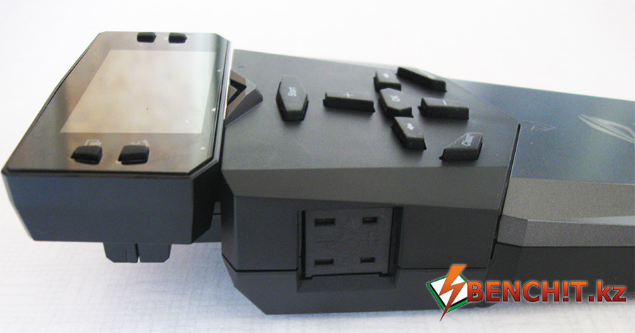
(Thermocouple connectors)
For example, in the photo below, you can see that the OC Panel shows temperatures of -113.4 and 25.9 degrees Celsius for the first and second thermocouples, respectively, and the processor multiplier is 45.

OC Panel shows temperatures very accurately. At one time, I had to buy a professional Fluke 54 II thermometer for $300 (from hand) with support for two thermocouples in order to record temperatures during extreme benchmarks. As a result, the presence of OC Panel in the kit allows you to save a good amount of money, plus it has excellent functionality. In addition, OC Panel can only work as a thermometer on other motherboards - just connect the SATA power supply. The profit is obvious.

At the bottom of the OC Panel, under the plastic cover, there are several more trump cards hidden. The first one is VGAHotwire. Using VGA Hotwire, you can voltmode a video card without using additional resistors. All you need to do is connect the wires to the appropriate points on the video card and to the Hotwire. Unfortunately, the story of what a video card voltmod is and how to do it is beyond the scope of this article, but for those who know what it is, this functionality is very useful. I tested the functionality of VGA Hotwire on the “old lady” Radeon HD 4850 - it works, and it’s incredibly convenient. In addition to VGA Hotwire, the OC Panel has four 4-pin connectors for connecting additional fans and two switches.
When the switch is activated SlowMode The processor multiplier is set to 8, thereby lowering the clock frequency. This is very useful when your processor speed is on the verge of stability, and you need to take a screenshot to save the result. Another, no less interesting switch is PauseButton. When activated, the entire system is paused. Imagine the situation: you are doing extreme overclocking without a partner, and suddenly, in the process of passing the test, you notice that you need to add liquid nitrogen to the processor cup, but the thermos has already run out of nitrogen. You need to go and fill the thermos, pouring nitrogen from the Dewar flask. We pause our system - it behaves as if it is frozen. We fill the thermos with nitrogen, fill the glass, press pause and the test continues.
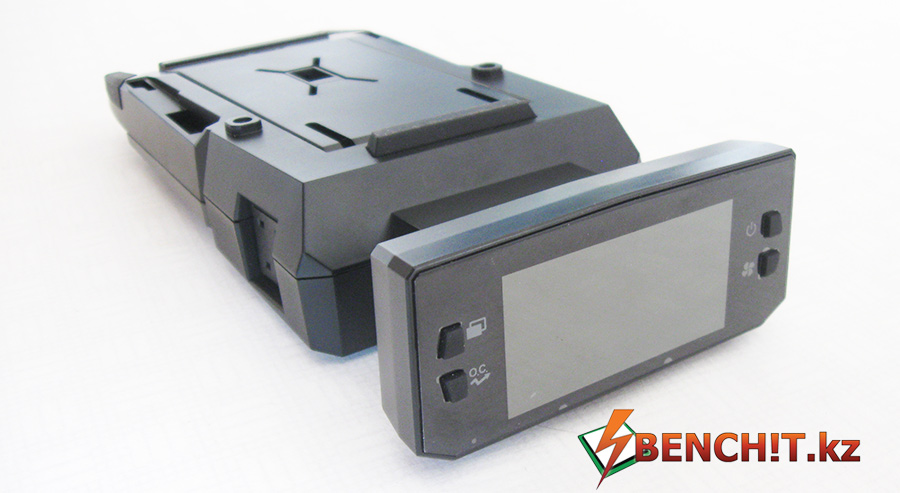
If you don't need all this functionality, you can fold the OC Panel and insert it into the five-inch bay dock that comes with it. As a result, you get a sophisticated “reobass”, with control over temperatures, frequencies and noise levels.

Cooling and appearance
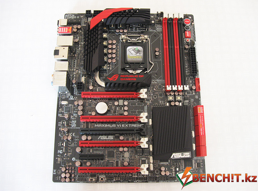
In terms of design, ASUS Maximus VI Extreme is not much different from its counterparts in the ASUS ROG family. There is the same black PCB, red/black slots and black-red radiators.
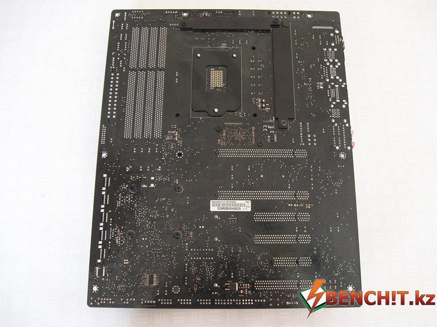
Nothing extraordinary happens on the reverse side of the board either, except perhaps the presence of a backplate for power system radiators, which also serves as a heat remover from the drivers.

The radiator has a comb and consists of two sections, which are connected to each other by one copper heat pipe.

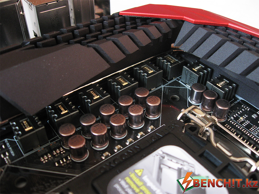
In terms of the shape of the comb, and in general, in terms of its design, the radiator looks quite strict - apparently no one is going to joke here.

Each throttle has an ASUS engraving on the gold-plated brackets. Such jewelry work in some sense enhances the elitism effect of the product. But the ASUS Maximus VI Extreme has only eight phases allocated for powering the processor. According to my observations, ASUS has not changed the eight-phase design on its flagship solutions for several generations. I asked ASUS why the company does not enter the race for the number of phases when competitors can have 16 or more. As a result, I received a completely objective answer: “ASUS uses exactly as many phases as are actually required.”
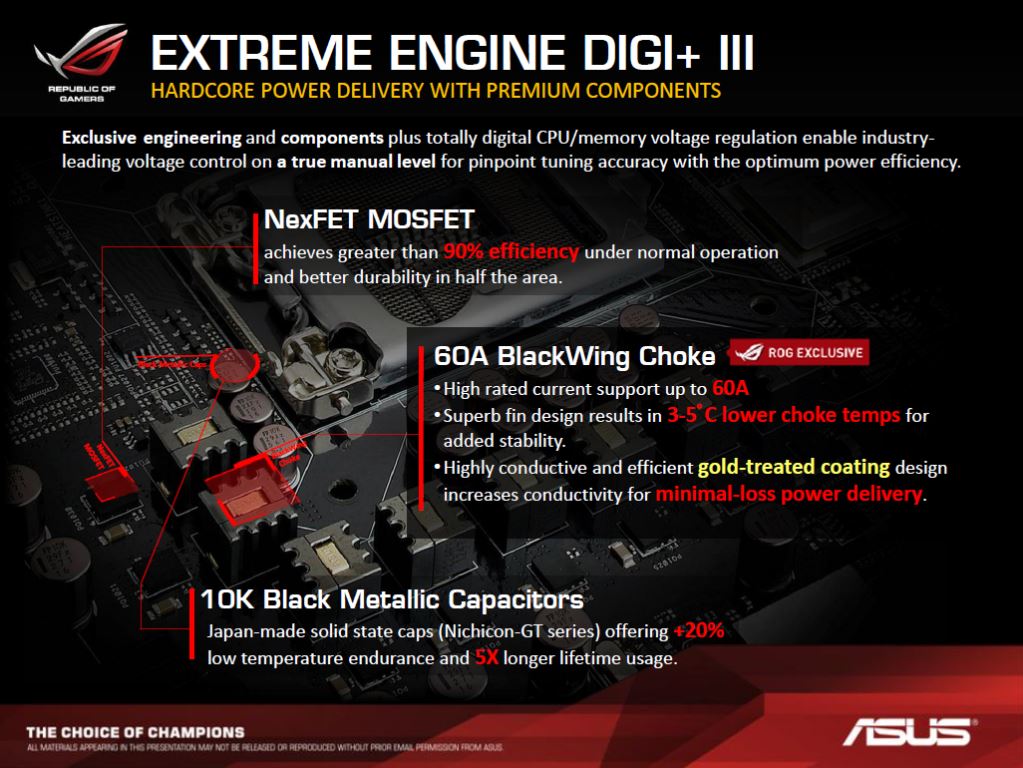
As it turned out, mosfets used in solutions ASUS ROG, 90% more efficient than others, and the chokes themselves are capable of withstanding peak current loads of up to 60A, which is more than enough even in extreme conditions. Another important point is that the power batteries practically do not heat up: when I was in the Moscow office of ASUS, a famous Russian overclocker Vladislav "slamms" Zakharov demonstrated extreme overclocking on a board with heatsinks completely removed from the power circuit. The board operated without any problems at 6 GHz for several hours without heatsinks.

Four- and eight-pin connectors are used to power the processor.

ASUS Maximus VI Extreme has four memory slots with dual channel support. The maximum supported memory frequency, according to the official documentation, is 3100 MHz (ASUS is actually being modest), and the maximum capacity is 32 GB.
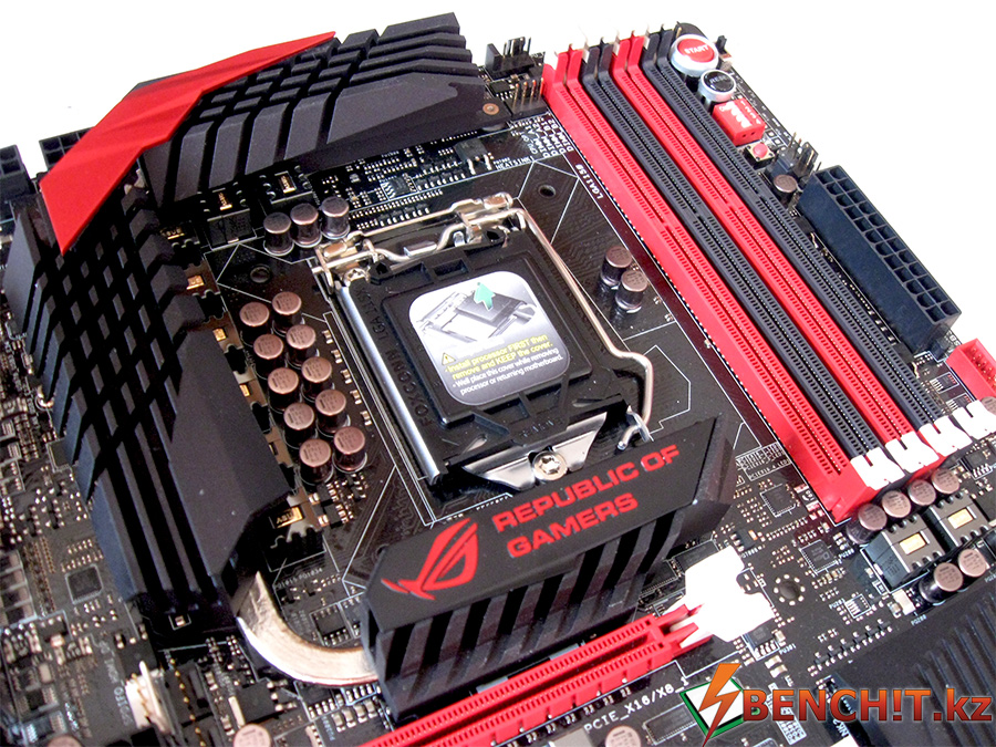
The memory slots are located quite close to the first PCIe slot, although there are no problems when installing a long video card. However, if you plan to install a nitrogen cup for memory, then when using sufficiently long cards you need to be very careful: the edges of the nitrogen cup for memory in inexperienced hands can touch the video card contacts on the back of the printed circuit board. But there are two points here: firstly, a lot depends on the design of the glass itself, and secondly, if you don’t do this, then such a situation is, in principle, unlikely to ever arise.
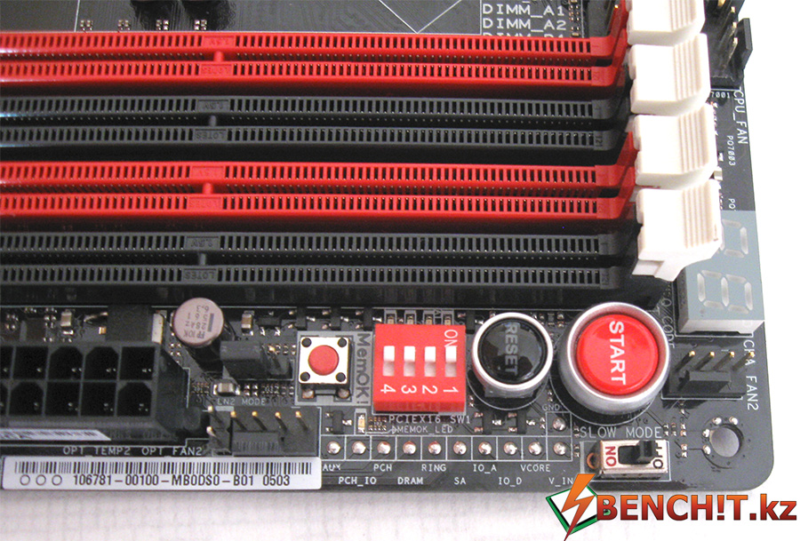
The space on the right side of the RAM slots carries a functional and information load. I’ll start with the fact that it’s clear even without additional comments: there is an LED POST code indicator, Start and Reset buttons, and the MemOK button, well known from ASUS products! and voltage measurement points for the main power supplies. Unlike the ASUS Maximus V Extreme, the VGA Hotwire connectors were moved from this area to the OC Panel, which allowed ASUS to release the Maximus VI Extreme in the ATX form factor, while its predecessor had the EATX form factor. In the same part there is a group of four toggle switches that turn off the corresponding PCIe x16 slot, switch Slow Mode, which also has a jumper LN2 Mode. LN2 Mode activates additional options and profiles in the UEFI BIOS, which may be useful for fans of extreme overclocking.

It has 10 SATA 3.0 ports, which is quite a lot. The first six SATA ports are implemented using the Intel Z87 chipset, the remaining four are implemented using controllers ASMedia ASM1061. It is also necessary to take into account that the fifth port is disabled when mPCIe COMBO II installed NGFF SSD.

The chipset itself, Intel Z87, is cooled by a fairly massive black radiator, so there is no need to think about any overheating here either.

In the lower area of the motherboard there are connectors for connecting the front panel of the case, thermocouples, two connectors for connecting front USB 2.0, two four-pin connectors for connecting fans, and in the lower right corner there is a button for switching between BIOS chips.

There are two BIOS chips on the motherboard, and each of them has an LED indicator indicating the currently active chip.
Just below the last PCIe X16 slot there are ROG_EXT and TB_HEADER contact groups. TB_HEADER is needed for Thunderbolt connection, and ROG_EXT is used for OC Panel connection.
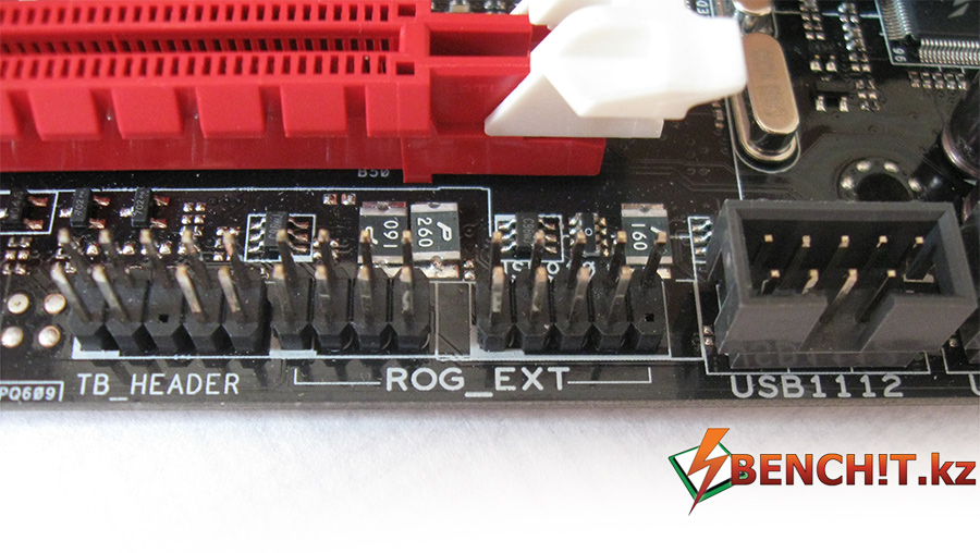
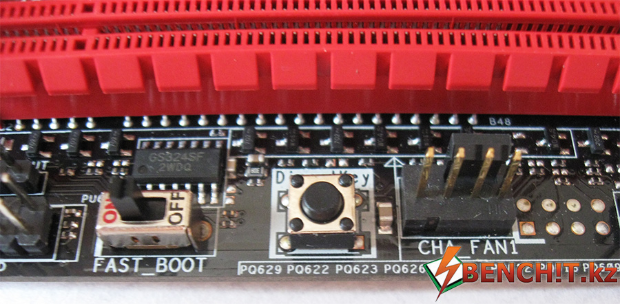
In addition, nearby are the FAST_BOOT switch, which allows you to enable/disable fast boot (I assume for systems installed in UEFI mode) and the DirectKey button. After pressing DirectKey, the operating system shuts down, and after turning on, the board enters the BIOS.

ASUS Maximus VI Extreme is equipped with five PCIe x16 ports, three of which use the PLX 8747 controller to expand PCIe lanes. Thanks to the additional controller, it is possible to use 4-Way SLI and 4-Way CrossFireX. The organization diagram for Multi-GPU configurations is presented below:

By the way, when using several video cards, it is recommended to connect additional power to PCIe:
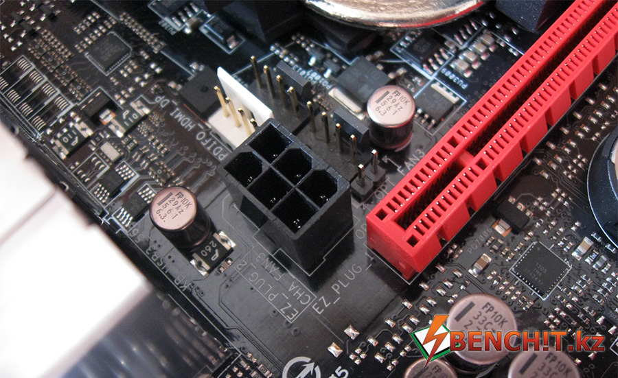
I was sincerely surprised when I noticed that the flagship motherboard from ASUS lacked a proprietary sound solution SupremeFX, which has been actively used by the manufacturer in the ASUS ROG line for several years.
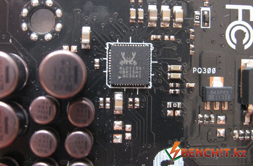
ASUS Maximus VI Extreme uses sound codec, which is widely used in many motherboards on Intel based Z87. For example, the same sound codec is installed on, which also recently came into my hands. Of course, SupremeFX has previously been based on some popular audio codec, depending on the generation, but with the use of improved binding. And recently, a path with red LED lighting has been installed, which gives a certain aesthetic appearance. If we think soberly, then Maximus VI Extreme is an overclocker's product. And for us, overclockers, in principle, the presence of sound as such does not matter.

The Gigabit controller is responsible for the network capabilities of the motherboard. Intel I217V, which also managed to “register” on many motherboards based on Intel Z87.

The rear panel houses the Clear CMOS and ROG Connect buttons, two USB 2.0 ports, one of which can be used for ROG Connect, six USB 3.0 ports, one RJ45 connector, S/PDIF optical output, HDMI, DisplayPort, a combined PS/2 port for a mouse /keyboard and six audio jacks.
UEFI BIOS Features
Testing and overclocking ASUS Maximus VI Extreme
The classic method of testing overclocking products in our testlab, which is the ASUS Maximus VI Extreme motherboard, is extreme overclocking. It has already become the custom that everything that claims to be the “best of the best” is subjected to extreme torture and torment. Our heroine is no exception.
First of all, I decided to find out the maximum clock speed that the ASUS Maximus VI Extreme can master under extreme conditions. At the beginning of the article I threw some words of disappointment towards the Haswell architecture, but in fact it’s not all that bad.
Let's go back to my Core i7-4770K processor. Reaching the 6 GHz barrier was not a big problem for him. Moreover, I managed to get 6.4 GHz on this processor:

But the processor cannot work stably under load at such a clock frequency - I decided to “run through” the rest of the processor tests, and its operating frequencies turned out to be lower. In the single-threaded PiFast test, I managed to get a result of 11.58 at 5.7 GHz under Windows control 7 X64.

Not my best result, however, this test is quite suitable for quickly checking stability in 2D tests.

The test was completed at a frequency of 5.8 GHz, and the result was 3.992 seconds. For comparison, your best result in wPrime32 3.681 sec, I got on Core processor i7-3770K with a frequency of 6372.9 MHz. Obviously, in terms of “performance per Megahertz” in this test, Haswell looks very interesting. It's a pity that not all Haswells can pass this test at frequencies above 6 GHz.
The next, even more difficult test is wPrime with a task size of 1024M. To pass this test, I had to lower the processor clock speed to 5.7 GHz. The result was as follows:

126.706 seconds is my best result in wPrime 1024 and is in the top 20 results in this test among Haswell processors.


The final result in CineBench R11.5 is 12.82 pts. This is my best result in CineBench. For comparison, on a Core i7-3770K processor with a frequency of 6,218.35 MHz, I got a result of 12.54 pts. Once again, the advantage of the Haswell architecture over Ivy Bridge is obvious: the former has a lower clock speed of 418 MHz, and the final result is higher.
The last test was Intel XTU - a test that is considered the toughest, motherboard and processor killer, and which is based on the multi-threaded Prime95 base.

In order to pass this test, I was forced to reduce the processor clock speed to 5.5 GHz. The final score of 1343 points is again my best result, but not the best among Haswell even at the same clock speed. I will improve!
Some photos from the bench session:


Conclusion
To be honest, it is very difficult for me to say anything in conclusion. It’s difficult because the amount of positive emotions after such a detailed acquaintance with ASUS Maximus VI Extreme is really off scale. Yes, the degree of success of overclocking, especially in the case of Haswell, is largely determined by the processor instance itself. But ASUS Maximus VI Extreme is a board designed to win and set world records, not only in processor tests, but also, thanks to graphics. Absolute stability, an incredible amount of fine-tuning settings in the BIOS, an excellent power system, support for 4-Way SLI and 4-Way CrossFireX - an uncompromising solution. This is the best board that has ever been in my hands. Yes, of course, in American retail it costs quite a bit of $400 (I’m afraid to imagine how much it will cost here), but let’s remember the truly revolutionary technology that ASUS implemented when developing the Maximus VI Extreme - OC Panel. Do you remember how much it cost me to buy a thermometer for two thermocouples? For 300 evergreen dollars. And in the case of ASUS Maximus VI Extreme, it comes included. In addition, OC Panel is not only a high-precision thermometer, it is very primitive to perceive it as such - it is a control console for almost the entire system: control of the multiplier per processor, voltage per core/cache, voltage per memory, voltage per core/memory/PLL of two video cards So consider what's what. My conclusion: - this is the best motherboard created for overclockers in the entire history of personal computers!
ASUS Maximus VI Extreme earns the top awards of Editor's Choice, Top Pick, and Overclocker's Choice for its outstanding features and quality.
Thanks:
- CompaniesASUS for the sample provided for testingASUSMaximusVIExtreme and patience shown.


