Unusual sounds and sound effects, obtained using simple radio-electronic attachments on CMOS chips, are able to capture the imagination of readers.
The circuit of one of these set-top boxes, shown in Figure 1, was born in the process of various experiments with the popular K176LA7 (DD1) CMOS chip.

Rice. 1. Electrical diagram of "strange" sound effects.
This circuit implements a whole cascade of sound effects, especially from the animal world. Depending on the position of the variable resistor motor installed at the input of the circuit, you can get sounds that are almost real to the ear: “croaking of a frog”, “nightingale’s trill”, “meowing of a cat”, “mooing of a bull” and many, many others. Even various human inarticulate combinations of sounds like drunken exclamations and others.
As is known, the nominal supply voltage of such a microcircuit is 9 V. However, in practice, to achieve special results, it is possible to deliberately lower the voltage to 4.5-5 V. In this case, the circuit remains operational. Instead of a 176 series chip in this option It is quite appropriate to use its more widespread analogue of the K561 series (K564, K1564).
Oscillations to the sound emitter BA1 are supplied from the output of the intermediate logical element of the circuit.
Let's consider the operation of the device in the "wrong" power supply mode - at a voltage of 5 V. As a power source, you can use batteries from cells (for example, three AAA cells connected in series) or a stabilized mains power supply with an oxide capacitor filter installed at the output with a capacity of 500 µF with an operating voltage of at least 12 V.
A pulse generator is assembled on elements DD1.1 and DD1.2, triggered by a “high voltage level” at pin 1 of DD1.1. The pulse frequency of the audio frequency generator (AF), when using the specified RC elements, at the output of DD1.2 will be 2-2.5 kHz. The output signal of the first generator controls the frequency of the second (assembled on elements DD1.3 and DD1.4). However, if you “remove” the pulses from pin 11 of element DD1.4, there will be no effect. One of the terminal element inputs is controlled through resistor R5. Both generators work in close conjunction with each other, self-exciting and implementing a dependence on the input voltage in unpredictable bursts of pulses at the output.
From the output of element DD1.3, pulses are sent to a simple current amplifier on transistor VT1 and, amplified many times, are reproduced by piezo emitter BA1.
About details
Any low-power silicon pnp transistor, including KT361 with any letter index, is suitable as VT1. Instead of the BA1 emitter, you can use a TESLA telephone capsule or a domestic DEMSH-4M capsule with a winding resistance of 180-250 Ohms. If it is necessary to increase the sound volume, it is necessary to supplement the basic circuit with a power amplifier and use a dynamic head with a winding resistance of 8-50 Ohms.
I advise you to use all values of resistors and capacitors indicated in the diagram with deviations of no more than 20% for the first elements (resistors) and 5-10% for the second (capacitors). Resistors are MLT type 0.25 or 0.125, capacitors are MBM, KM type and others, with a slight tolerance for the influence of ambient temperature on their capacitance.
Resistor R1 with a nominal value of 1 MOhm is variable, with a linear characteristic of resistance change.
If you need to settle on any one effect you like, for example, “the cackling of geese,” you should achieve this effect by rotating the engine very slowly, then turn off the power, remove the variable resistor from the circuit and, having measured its resistance, install a constant resistor of the same value in the circuit.
With proper installation and serviceable parts, the device begins to work (make sounds) immediately.
In this embodiment, sound effects (frequency and interaction of generators) depend on the supply voltage. When the supply voltage increases by more than 5 V, to ensure the safety of the input of the first element DD1.1, it is necessary to connect a limiting resistor with a resistance of 50 - 80 kOhm into the conductor gap between the upper contact R1 in the circuit and the positive pole of the power source.
The device in my house is used for playing with pets and training the dog.
Figure 2 shows a diagram of a variable audio frequency (AF) oscillation generator.

Fig.2. Electrical circuit of an audio frequency generator
The AF generator is implemented on the logical elements of the K561LA7 microcircuit. A low-frequency generator is assembled on the first two elements. It controls the oscillation frequency of the high-frequency generator on elements DD1.3 and DD1.4. This means that the circuit operates at two frequencies alternately. To the ear, mixed vibrations are perceived as a “trill”.
The sound emitter is a piezoelectric capsule ZP-x (ZP-2, ZP-Z, ZP-18 or similar) or a high-resistance telephone capsule with a winding resistance of more than 1600 Ohms.
The ability of the K561 series CMOS chip to operate over a wide range of supply voltages is used in the audio circuit in Figure 3.

Fig.3. Electrical circuit of a self-oscillating generator.
Self-oscillating generator on the K561J1A7 microcircuit (logic elements DD1.1 and DD1.2-fig.). It receives the supply voltage from the control circuit (Fig. 36), consisting of an RC charging chain and a source follower on the field-effect transistor VT1.
When the SB1 button is pressed, the capacitor in the gate circuit of the transistor is quickly charged and then slowly discharged. The source follower has a very high resistance and has almost no effect on the operation of the charging circuit. At the output of VT1, the input voltage is “repeated” - and the current is sufficient to power the elements of the microcircuit.
At the output of the generator (the connection point with the sound emitter), oscillations with decreasing amplitude are formed until the supply voltage becomes less than permissible (+3 V for K561 series microcircuits). After this, the vibrations stop. The oscillation frequency is selected to be approximately 800 Hz. It depends and can be adjusted by capacitor C1. When the AF output signal is applied to a sound emitter or amplifier, you can hear the sounds of a “cat meowing”.
The circuit presented in Figure 4 allows you to reproduce the sounds made by a cuckoo.

Rice. 4. Electrical circuit of a device with imitation of a “cuckoo”.
When you press the S1 button, capacitors C1 and C2 are quickly charged (C1 through diode VD1) to the supply voltage. The discharge time constant for C1 is about 1 s, for C2 - 2 s. The discharge voltage C1 on two inverters of the DD1 chip is converted into a rectangular pulse with a duration of about 1 s, which, through resistor R4, modulates the frequency of the generator on the DD2 chip and one inverter of the DD1 chip. During the pulse duration, the generator frequency will be 400-500 Hz, in its absence - approximately 300 Hz.
The world around us is full of sounds. In the city these are mainly sounds associated with the development of technology. Nature gives us more pleasant sensations - the singing of birds, the sound of the sea surf, the crackling of a fire on a hiking trip. Often, some of these sounds need to be reproduced artificially - imitated, simply out of desire, or based on the needs of your technical modeling club, or when staging a play in a drama club. Let's look at descriptions of several sound simulators.
Intermittent siren sound simulator |

Let's start with the simplest design, this is a simple siren sound simulator. There are single-tone sirens, which produce a sound of one tone, intermittent ones, when the sound gradually increases or decreases, and then is interrupted or becomes single-tone, and two-tone ones, in which the tone of the sound periodically changes abruptly.
A generator is assembled using transistors VT1 and VT2 using an asymmetrical multivibrator circuit. The simplicity of the generator circuit is explained by the use of transistors of different structures, which made it possible to do without many of the parts necessary to build a multivibrator using transistors of the same structure.

Siren sound simulator - circuit with two transistors
The oscillations of the generator, and therefore the sound in the dynamic head, appear due to the positive feedback between the collector of transistor VT2 and the base of VT1 through capacitor C2. The tonality of the sound depends on the capacitance of this capacitor.
When switch SA1 supplies supply voltage to the generator, there will be no sound in the head yet, since there is no bias voltage based on transistor VT1. The multivibrator is in standby mode.
As soon as the SB1 button is pressed, capacitor C1 begins to charge (through resistor R1). The bias voltage at the base of transistor VT1 begins to increase, and at a certain value the transistor opens. The sound of the desired tonality is heard in the dynamic head. But the bias voltage increases, and the tone of the sound changes smoothly until the capacitor is fully charged. The duration of this process is 3...5 s and depends on the capacitance of the capacitor and the resistance of resistor R1.
As soon as you release the button, the capacitor will begin to discharge through resistors R2, R3 and the emitter junction of transistor VT1. The tone of the sound changes smoothly, and at a certain bias voltage based on transistor VT1, the sound disappears. The multivibrator returns to standby mode. The duration of discharge of the capacitor depends on its capacitance, the resistance of resistors R2, R3 and the emitter junction of the transistor. It is selected in such a way that, as in the first case, the tonality of the sound changes within 3...5 s.
In addition to those indicated in the diagram, the simulator can use other low-power silicon transistors of the corresponding structure with a static current transfer coefficient of at least 50. In extreme cases, germanium transistors are also suitable - MP37A, MP101 can work in place of VT1, and instead of VT2 - MP42A, MP42B with possibly large static transmission coefficient. Capacitor C1 - K50-6, C2 - MBM, resistors - MLT-0.25 or MLT-0.125. Dynamic head - power 0.G...1 W with a voice coil with a resistance of 6...10 Ohms (for example, head 0.25GD-19, 0.5GD-37, 1GD-39). The power source is a Krona battery or two 3336 batteries connected in series. The power switch and button are of any design.
In standby mode, the simulator consumes a small current - it depends mainly on the reverse collector current of the transistors. Therefore, the switch contacts can be closed for a long time, which is necessary, say, when using a simulator as apartment call. When the contacts of the SB1 button close, the current consumption increases to approximately 40 mA.
Looking at the circuit of this simulator, it is easy to notice an already familiar unit - a generator assembled on transistors VT3 and VT4. The previous simulator was assembled using this scheme. Only in this case the multivibrator does not work in standby mode, but in normal mode. To do this, a bias voltage from the divider R6R7 is applied to the base of the first transistor (VT3). Note that transistors VT3 and VT4 have swapped places compared to the previous circuit due to a change in the polarity of the supply voltage.
So, a tone generator is assembled on transistors VT3 and VT4, which sets the first tone of the sound. On transistors VT1 and VT2 a symmetrical multivibrator is made, thanks to which a second tone of sound is obtained.
It happens like this. During operation of the multivibrator, the voltage at the collector of transistor VT2 is either present (when the transistor is closed) or disappears almost completely (when the transistor is opened). The duration of each state is the same - approximately 2 s (i.e., the multivibrator pulse repetition rate is 0.5 Hz). Depending on the state of transistor VT2, resistor R5 bypasses either resistor R6 (through resistor R4 connected in series with resistor R5) or R7 (through the collector-emitter section of transistor VT2). The bias voltage at the base of transistor VT3 changes abruptly, so a sound of one or another tone is heard from the dynamic head.
What is the role of capacitors C2, SZ? They allow you to get rid of the influence of the tone generator on the multivibrator. If they are absent, the sound will be somewhat distorted. The capacitors are connected in back-to-back series because the polarity of the signal between the collectors of transistors VT1 and VT2 periodically changes. A conventional oxide capacitor under such conditions performs worse than a so-called non-polar one, for which the polarity of the voltage at the terminals does not matter. When two polar oxide capacitors are connected in this way, an analogue of a non-polar capacitor is formed. True, the total capacitance of the capacitor becomes half that of each of them (of course, with their capacitance being the same).

Siren sound simulator using four transistors
This simulator can use the same types of parts as the previous one, including the power supply. To supply the supply voltage, both a regular switch with a fixed position and a push-button switch are suitable if the simulator will work as an apartment bell.
Some parts are mounted on printed circuit board(Fig. 29) from one-sided foil fiberglass. Installation can also be mounted in the usual way- using mounting racks for soldering parts leads. The board is placed in a suitable housing in which the dynamic head and power supply are installed. The switch is placed on the front wall of the housing or mounted near front door(if there is already a bell button, its terminals are connected by insulated conductors to the corresponding circuits of the simulator).
As a rule, a simulator installed without errors starts working immediately. But if necessary, it is easy to adjust to obtain a more pleasant sound. Thus, the tonality of the sound can be slightly lowered by increasing the capacitance of capacitor C5 or increased by decreasing it. The range of tone changes depends on the resistance of resistor R5. The duration of the sound of a particular key can be changed by selecting capacitors C1 or C4.
This can be said about the next sound simulator if you listen to its sound. Indeed, the sounds produced by the dynamic head resemble the exhausts characteristic of a car, tractor or diesel locomotive engine. If the models of these machines are equipped with the proposed simulator, they will immediately come to life.
According to the circuit, the engine operation simulator is somewhat reminiscent of a single-tone siren. But the dynamic head is connected to the collector circuit of transistor VT2 through the output transformer T1, and the bias and feedback voltages are supplied to the base of transistor VT1 through variable resistor R1. For direct current it is connected by a variable resistor, and for feedback formed by a capacitor - by a voltage divider (potentiometer). When the resistor slider is moved, the frequency of the generator changes: when the slider is moved down the circuit, the frequency increases, and vice versa. Therefore, a variable resistor can be considered an accelerator that changes the rotation speed of the “engine” shaft, and therefore the frequency of sound exhaust.

Sound simulator engine diagram on two transistors
Transistors KT306, KT312, KT315 (VT1) and KT208, KT209, KT361 (VT2) with any letter indices are suitable for the simulator. Variable resistor - SP-I, SPO-0.5 or any other, possibly smaller in size, constant - MLT-0.25, capacitor - K50-6, K50-3 or other oxide, with a capacity of 15 or 20 μF for the rated voltage not below 6 V. The output transformer and dynamic head are from any small-sized (“pocket”) transistor receiver. One half of the primary winding is used as winding I. The power source is a 3336 battery or three 1.5 V cells connected in series.
Depending on where you will use the simulator, determine the dimensions of the board and case (if you intend to install the simulator not on the model).
If, when you turn on the simulator, it works unstably or there is no sound at all, swap the leads of capacitor C1 with the positive lead to the collector of transistor VT2. By selecting this capacitor you can set the desired limits for changing the speed of the “engine”.
Drip... drip... drip... - sounds come from the street when it rains or in the spring drops of melting snow fall from the roof. These sounds have a calming effect on many people, and according to some, they even help them fall asleep. Well, perhaps you will need such a simulator for the soundtrack in your school drama club. The construction of the simulator will take only a dozen parts.
A symmetrical multivibrator is made on transistors, the loads of which are the high-impedance dynamic heads BA1 and BA2 - “drop” sounds are heard from them. The most pleasant “drop” rhythm is set with variable resistor R2.

Drop sound simulator - circuit with two transistors
To reliably “start” a multivibrator at a relatively low supply voltage, it is advisable to use transistors (they can be of the MP39 - MP42 series) with the highest possible static current transfer coefficient. Dynamic heads should have a power of 0.1 - 1 W with a voice coil with a resistance of 50 - 100 Ohms (for example, 0.1GD-9). If such a head is not available, you can use DEM-4m capsules or similar ones that have the specified resistance. Higher impedance capsules (for example, from TON-1 headphones) will not provide the required sound volume. The remaining parts can be of any type. Power source - 3336 battery.
The simulator parts can be placed in any box and dynamic heads (or capsules), a variable resistor and a power switch can be mounted on its front wall.
When checking and adjusting the simulator, you can change its sound by selecting constant resistors and capacitors within a wide range. If in this case you need a significant increase in the resistances of resistors R1 and R3, it is advisable to install a variable resistor with a high resistance - 2.2; 3.3; 4.7 kOhm to provide a relatively wide range of droplet frequency control.
Bouncing ball sound simulator circuit |
Want to hear a steel ball bounce off a ball bearing on a steel or cast iron plate? Then assemble the simulator according to the diagram shown in Fig. 32. This is a variant of an asymmetrical multivibrator, used, for example, in a siren. But unlike a siren, the proposed multivibrator does not have pulse repetition frequency control circuits. How does the simulator work? Just press (briefly) the SB1 button - and capacitor C1 will charge to the voltage of the power source. After releasing the button, the capacitor will become the source that powers the multivibrator. While the voltage on it is high, the volume of the “blows” of the “ball” reproduced by the dynamic head BA1 is significant, and the pauses are relatively long.


Simulator of the sound of a bouncing ball - transistor circuits
Gradually, as capacitor C1 discharges, the nature of the sound will change - the volume of the “beats” will begin to decrease, and the pauses will decrease. Finally, a characteristic metallic rattling sound will be heard, after which the sound will stop (when the voltage on capacitor C1 drops below the opening threshold of the transistors).
Transistor VT1 can be any of the MP21, MP25, MP26 series, and VT2 can be any of the KT301, KT312, KT315 series. Capacitor C1 - K.50-6, C2 - MBM. The dynamic head is 1GD-4, but another one with good diffuser mobility and a possibly larger area will do. The power source is two batteries 3336 or six cells 343, 373 connected in series.
The parts can be mounted inside the simulator body by soldering their leads to the pins of the button and the dynamic head. Batteries or cells are attached to the bottom or walls of the case with a metal bracket.
When setting up the simulator, the most characteristic sound is achieved. To do this, select capacitor C1 (it determines the total duration of the sound) within 100...200 µF or C2 (the duration of pauses between “beats” depends on it) within 0.1...0.5 µF. Sometimes, for the same purposes, it is useful to select transistor VT1 - after all, the operation of the simulator depends on its initial (reverse) collector current and the static current transfer coefficient.
The simulator can be used as an apartment bell if you increase the volume of its sound. The easiest way to do this is to add two capacitors to the device - SZ and C4 (Fig. 33). The first of them directly increases the sound volume, and the second gets rid of the tone drop effect that sometimes appears. True, with such modifications the “metallic” sound tint characteristic of a real bouncing ball is not always preserved.
Transistor VT3 can be any of the GT402 series, resistor R1 - MLT-0.25 with a resistance of 22...36 Ohms. In place of VT3, transistors of the MP20, MP21, MP25, MP26, MP39 - MP42 series can operate, but the sound volume will be somewhat weaker, although significantly higher than in the original simulator.
Sea surf sound simulator circuit diagram |
By connecting a small set-top box to the amplifier of a radio, tape recorder or TV, you can get sounds reminiscent of the sound of the sea surf.
The diagram of such a simulator attachment is shown in Fig. 35. It consists of several nodes, but the main one is the noise generator. It is based on a silicon zener diode VD1. The fact is that when a constant voltage exceeding the stabilization voltage is applied to the zener diode through a ballast resistor with a high resistance, the zener diode begins to “break through” - its resistance drops sharply. But thanks to the insignificant current flowing through the zener diode, such a “breakdown” does not cause any harm to it. At the same time, the zener diode seems to go into noise generation mode, the so-called “shot effect” of its pn junction appears, and at the zener diode terminals one can observe (of course, using a sensitive oscilloscope) a chaotic signal consisting of random oscillations, the frequencies of which lie in a wide range.
This is the mode in which the zener diode of the set-top box works. The ballast resistor mentioned above is R1. Capacitor C1, together with a ballast resistor and a zener diode, provides a signal of a certain frequency band, similar to the sound of surf noise.

Sea surf sound simulator circuit with two transistors
Of course, the amplitude of the noise signal is too small to feed it directly to the radio amplifier. Therefore, the signal is amplified by a cascade on transistor VT1, and from its load (resistor R2) goes to an emitter follower made on transistor VT2, which eliminates the influence of subsequent cascades of the set-top box on the operation of the noise generator.
From the emitter follower load (resistor R3), the signal is supplied to a cascade with a variable gain, assembled on transistor VT3. Such a cascade is needed so that it is possible to change the amplitude of the noise signal supplied to the amplifier, and thereby simulate the increase or decrease in the volume of the “surf”.
To carry out this task, transistor VT4 is included in the emitter circuit of transistor VT3, the base of which receives a signal from a control voltage generator - a symmetrical multivibrator on transistors VT5, VT6 - through resistor R7 and integrating circuit R8C5. In this case, the resistance of the collector-emitter section of transistor VT4 periodically changes, which causes a corresponding change in the gain of the cascade on transistor VT3. As a result, the noise signal at the cascade output (at resistor R6) will periodically rise and fall. This signal is supplied through the capacitor SZ to connector XS1, which is connected during operation of the set-top box to the input of the amplifier used.
The pulse duration and repetition frequency of the multivibrator can be changed by resistors R10 and R11. Together with resistor R8 and capacitor C4, they determine the duration of the rise and fall of the control voltage supplied to the base of transistor VT4.
All transistors can be the same, KT315 series with the highest possible current transfer coefficient. Resistors - MLT-0.25 (MLT-0.125 is also possible); capacitors Cl, C2 - K50-3; NW, S5 - S7 - K.50-6; C4 - MBM. Other types of capacitors are suitable, but they must be designed for a rated voltage not lower than that indicated in the diagram.
Almost all parts are mounted on a circuit board (Fig. 36) made of foil material. Place the board in a case of suitable dimensions. Connector XS1 and clamps XT1, XT2 are fixed on the side wall of the case.
The set-top box is powered from any DC source with a stabilized and adjustable output voltage (from 22 to 27 V).
As a rule, there is no need to set up the console. It starts working immediately after power is applied. It is easy to check the operation of the set-top box using high-impedance headphones TON-1, TON-2 or other similar ones, plugged into the sockets of the XS1 “Output” connector.
The nature of the sound of the “surf” is changed (if necessary) by selecting the supply voltage, resistors R4, R6, as well as bypassing the sockets of the XS1 connector with a capacitor C7 with a capacity of 1000...3000 pF.
And here is another such sound simulator, assembled according to a slightly different scheme. It contains an audio amplifier and a power supply, so this simulator can be considered a complete design.
The noise generator itself is assembled on transistor VT1 according to the so-called super-regenerator circuit. It is not very easy to understand the operation of a superregenerator, so we will not consider it. Just understand that this is a generator in which oscillations are excited due to positive feedback between the output and input of the cascade. In this case, this connection is carried out through the capacitive divider C5C4. In addition, the super-regenerator is not excited constantly, but in flashes, and the moment of occurrence of the flashes is random. As a result, a signal appears at the output of the generator, which is heard as noise. This signal is often called “white noise”.

Sea surf sound simulator, a more complex version of the circuit
The DC operating mode of the superregenerator is set by resistors Rl, R2, R4. Inductor L1 and capacitor C6 do not affect the operating mode of the cascade, but protect the power circuits from the penetration of noise signals into them.
The L2C7 circuit determines the frequency band of “white noise” and allows you to obtain the largest amplitude of the allocated “noise” oscillations. Next, they pass through the low-pass filter R5C10 and capacitor C9 to the amplifier stage assembled on transistor VT2. The supply voltage to this stage is supplied not directly from source GB1, but through a cascade assembled on transistor VT3. This is an electronic key that periodically opens with pulses arriving at the base of the transistor from a multivibrator assembled on transistors VT4, VT5. During periods when transistor VT4 is closed, VT3 opens, and capacitor C12 is charged from source GB1 through the collector-emitter section of transistor VT3 and trimming resistor R9. This capacitor is a kind of battery that powers the amplifier stage. As soon as transistor VT4 opens, VT3 closes, capacitor C12 is discharged through trimming resistor R11 and the collector-emitter circuit of transistor VT2.
As a result, at the collector of transistor VT2 there will be a noise signal modulated in amplitude, i.e., periodically increasing and decreasing. The duration of the rise depends on the capacitance of capacitor C12 and the resistance of resistor R9, and the decline - on the capacitance of the specified capacitor and the resistance of resistor R11.
Through the capacitor SP, the modulated noise signal is supplied to an audio amplifier made on transistors VT6 - VT8. At the input of the amplifier there is a variable resistor R17 - a volume control. From its engine, the signal is supplied to the first stage of the amplifier, assembled on a VT6 transistor. This is a voltage amplifier. From the cascade load (resistor R18), the signal is supplied through capacitor C16 to the output stage - a power amplifier made using transistors VT7, VT8. The collector circuit of transistor VT8 includes a load - dynamic head BA1. From it you can hear the sound of “sea surf”. Capacitor C17 weakens the high-frequency, “whistle” components of the signal, which somewhat softens the sound timbre.
About the details of the simulator. Instead of the KT315V transistor (VT1), you can use other transistors of the KT315 series or the GT311 transistor with any letter index. The remaining transistors can be any of the MP39 - MP42 series, but with the highest possible current transfer coefficient. To obtain greater output power, it is advisable to use the VT8 transistor of the MP25, MP26 series.
Throttle L1 can be ready-made, type D-0.1 or another.
Inductance 30... 100 µH. If it is not there, you need to take a rod core with a diameter of 2.8 and a length of 12 mm from ferrite 400NN or 600NN and wind on it turn to turn 15...20 turns of PEV-1 0.2...0.4 wire. It is advisable to measure the resulting inductance of the inductor on a standard device and, if necessary, select it within the required limits by decreasing or increasing the number of turns.
Coil L2 is wound on a frame with a diameter of 4 and a length of 12 ... 15 mm from any insulating material using PEV-1 wire 6.3 - 24 turns with a tap from the middle.
Fixed resistors - MLT-0.25 or MLT-0.125, tuning resistors - SPZ-16, variable - SPZ-Zv (it has a litany switch SA1). Oxide capacitors - K50-6; C17 - MBM; the rest are KM, K10-7 or other small-sized ones. Dynamic head - power 0.1 - I W with the highest possible voice coil resistance (so that the VT8 transistor does not overheat). The power source is two 3336 batteries connected in series, but the best results in terms of operating time will be obtained with six 373 cells connected in the same way. A suitable option, of course, is power supply from a low-power rectifier with a constant voltage of 6...9 V.
The simulator parts are mounted on a board (Fig. 38) made of foil material 1...2 mm thick. The board is installed in a case, on the front wall of which a dynamic head is mounted, and a power source is placed inside. The dimensions of the case largely depend on the dimensions of the power source. If the simulator is used only to demonstrate the sound of the sea surf, the power source can be a Krona battery - then the dimensions of the case will be sharply reduced, and the simulator can be mounted in the case of a small-sized transistor radio.
The simulator is set up like this. Disconnect resistor R8 from capacitor C12 and connect it to the negative power wire. Having set the maximum sound volume, select resistor R1 until characteristic noise (“white noise”) is obtained in the dynamic head. Then restore the connection between resistor R8 and capacitor C12 and listen to the sound in the dynamic head. By moving the slider of the tuning resistor R14, the most reliable and pleasant-to-hear frequency of the “sea waves” is selected. Next, by moving the slider of resistor R9, the duration of the rise of the “wave” is set, and by moving the slider of resistor R11, the duration of its decline is determined.
To get a high volume of “sea surf”, you need to connect the extreme terminals of the variable resistor R17 to the input powerful amplifier sound frequency. A better experience can be achieved by using a stereo amplifier with external acoustic systems operating in monophonic signal playback mode.
Rain noise sound simulator simple circuit |
If you want to listen to the beneficial effects of the measured noise of rain, forest or sea surf. Such sounds relax and calm.
Rain noise sound simulator - operational amplifier and counter circuit
The rain noise generator is made on a TL062 chip, which includes two operational amplifiers. Then the generated sound is amplified by transistor VT2 and sent to the speaker SP. For greater compliance, the HF audio spectrum is cut off by capacitance C8, which is controlled by field-effect transistor VT1, which essentially works as a variable resistance. Thus, we obtain automatic control of the imitator's tone.
The CD4060 counter has a timer with three shutdown time delays: 15, 30 and 60 minutes. Transistor VT3 is used as a generator power switch. By changing the values of resistance R16 or capacitance C10, we obtain different time intervals in the operation of the timer. By changing the value of resistor R9 from 47k to 150k, you can change the speaker volume.
 Some of the parts are mounted on a printed circuit board (Fig. 48), which is then placed inside a suitable housing. The battery is also installed there. The dynamic head and switch can be mounted on the front wall of the case.
 If all parts are in good working order and installed without errors, the simulator does not require any adjustment. Nevertheless, remember the following recommendations. The repetition frequency of trills can be changed by selecting resistor R5. Resistor R7, connected in series with the head, affects not only the sound volume, but also the frequency of the blocking oscillator. This resistor can be selected experimentally, temporarily replacing it with a variable wire resistor with a resistance of 2...3 Ohms. When achieving the highest sound volume, do not forget that distortion may appear, deteriorating the sound quality.
Rice. 48. Simulator circuit board
When repeating this simulator, in order to obtain the desired sound, it was necessary to slightly change the values of the parts and even rebuild the circuit. Here, for example, are the changes made to one of the designs. The chain C4, C5, R6 is replaced by a capacitor (oxide or other type) with a capacity of 2 μF, and instead of resistor R5, a chain of a series-connected constant resistor with a resistance of 33 kOhm and a trimmer resistance of 100 kOhm is included. Instead of the chain R2, C2, a capacitor with a capacity of 30 μF is included. Resistor R4 remained connected to the terminal of inductor L1, and between the terminal and the base of transistor VT2 (and therefore the positive terminal of capacitor C1) a resistor with a resistance of 1 kOhm was connected, and at the same time a resistor with a resistance of 100 kOhm was connected between the base and emitter of transistor VT2. In this case, the resistance of resistor R2 is reduced to 75 kOhm, and the capacitance of capacitor C1 is increased to 100 μF.
Such changes can be caused by the use of specific transistors, a transformer and inductor, a dynamic head, and other parts. Listing them makes it possible to experiment more widely with this simulator to obtain the desired sound.
In any case, the functionality of the simulator is maintained when the supply voltage changes from 6 to 9 V.
^ TRILLING THE NIGHTINGALE
Using part of the previous design, you can assemble a new simulator (Fig. 49) - the trill of a nightingale. It contains only one transistor, on which a blocking oscillator with two positive feedback circuits is made. One of them, consisting of inductor L1 and capacitor C2, determines the tonality of the sound, and the second, composed of resistors Rl, R2 and capacitor C1, determines the trill repetition period. Resistors Rl - R3 determine the operating mode of the transistor.

^
Rice. 49. Circuit of a nightingale trill simulator on one transistor
The output transformer, inductor and dynamic head are the same as in the previous design, the transistor is of the MP39 - MP42 series with the highest possible current transfer coefficient. Power source - any (from galvanic batteries or rectifier) with a voltage of 9... 12 V. Resistors - MLT-0.25, oxide capacitors - K50-6, capacitor SZ - MBM or another.
There are few parts in the simulator and you can arrange them yourself on a board made of insulating material. The relative position of the parts does not matter. Installation can be either printed or mounted, using racks for parts leads.
The sound of a simple simulator largely depends on the parameters of the transistor used. Therefore, setting up comes down to selecting parts to obtain the desired effect.
The tone of the sound is set by selecting the capacitor SZ (its capacity can be in the range from 4.7 to 33 µF), and the desired duration of the trills is by selecting resistor R1 (ranging from 47 to 100 kOhm) and capacitor C1 (from 0.022 to 0.047 µF). The plausibility of the sound largely depends on the operating mode of the transistor, which is set by selecting resistor R3 in the range from 3.3 to 10 kOhm. The setup will be greatly simplified if, instead of constant resistors R1 and R3, variables are temporarily installed with a resistance of 100 - 220 kOhm (R1) and 10 - 15 kOhm (R3).
If you want to use the simulator as a doorbell or sound alarm, replace the capacitor SZ with another, larger capacity (up to 2000 µF). Then, even with a short-term supply of power to the bell button, the capacitor will instantly charge and act as a battery, allowing you to maintain a sufficient duration of sound.
A diagram of a more complex simulator, which requires virtually no setup, is shown in Fig. 50. It consists of three symmetrical multivibrators that produce oscillations different frequencies. Let's say the first multivibrator, made on transistors VT1 and VT2, operates at a frequency of less than a hertz, the second multivibrator (it is made on transistors VT3, VT4) - at a frequency of several hertz, and the third (on transistors VT5, VT6) - at a frequency of more than a kilohertz. Since the third multivibrator is connected to the second, and the second to the first, the oscillations of the third multivibrator will be bursts of signals of different durations and slightly varying frequencies. These “bursts” are amplified by a cascade on the transistor VT7 and are fed through the output transformer T1 to the dynamic head BA1 - it converts the “bursts” of the electrical signal into the sounds of a nightingale trill.
Note that to obtain the required simulation, an integrating circuit R5C3 is installed between the first and second multivibrators, which allows “converting” the pulse voltage of the multivibrator into a smoothly rising and falling one, and between the second and third multivibrators a differentiating circuit C6R10 is connected, providing a shorter duration control voltage compared to with a prominent resistor R9.
The simulator can operate transistors of the MP39 - MP42 series with the highest possible current transfer coefficient. Fixed resistors - MLT-0.25, oxide capacitors - K50-6, other capacitors - MBM or other small-sized ones. Transformer - output from any transistor receiver with push-pull amplifier power. Half of the primary winding of the transformer is connected to the collector circuit of the transistor. Dynamic head - any low-power one, for example 0.1GD-6, 0.25GD-19. Power source - 3336 battery, switch - any design.

Rice. 50. Circuit of a nightingale trill simulator using six transistors
Some of the simulator parts are placed on a board (Fig. 51), which is then installed in a housing made of any material and suitable dimensions. A power source is placed inside the case, and a dynamic head is mounted on the front wall. You can also place a power switch here (when using the simulator as an apartment bell, instead of a switch, connect the bell button located at the front door with wires).

^
Rice. 51. Simulator circuit board
Testing the simulator begins with the third multivibrator. Temporarily connect the upper terminals of the resistors R12, R13 to the negative power wire. A continuous sound of a certain tone should be heard in the dynamic head. If you need to change the tone, just select capacitors C7, C8 or resistors R12, R13.
Then restore the previous connection of resistors R12, R13 and connect the upper terminals of resistors R7, R8 to the negative wire. The sound should become intermittent, but not yet similar to the singing of a nightingale.
If this is the case, remove the jumper between resistors R7, R8 and the negative wire. Now a sound similar to a nightingale trill should appear. A more accurate sound of the simulator can be achieved by selecting parts of the frequency-setting circuits of the first two multivibrators - base resistors and feedback capacitors.
^
FOR DIFFERENT VOICES
Some rearrangement of the circuit of the electronic “canary” - and now a circuit appears (Fig. 52) of another simulator, capable of producing the sounds of a wide variety of feathered inhabitants of the forest. Moreover, adjusting the simulator to a particular sound is relatively simple - just move the handle of one or two switches to the appropriate position.
As in the electronic “canary”, both transistors operate in a multivibrator, and VT2 is also part of the blocking oscillator. The frequency-setting circuits of the simulator include sets of capacitors of different capacities, which can be connected using switches: using switch SA1, the tonality of the sound is changed, and using SA2, the repetition frequency of trills is changed.
In addition to those indicated in the diagram, other low-power germanium transistors can operate with the highest possible transmission coefficient (but not less than 30). Oxide capacitors - K50-6, the rest - MBM, KLS or other small-sized ones. All resistors are MLT-0.25 (MLT-0.125 is possible). The choke, output transformer and dynamic head are the same as in the “canary”. Switches - any design. Suitable, for example, are 11P2N biscuit switches (11 positions, 2 directions - it is made up of two boards with contacts connected by one axis). Although such a switch has 11 positions, it is not difficult to bring them to the required six by moving the limiter (it is located on the switch handle under the nut) into the corresponding hole in the base.

Rice. 52. Scheme of a universal trill simulator

Rice. 53. Simulator circuit board
Some parts are mounted on a printed circuit board (Fig. 53). The transformer and inductor are attached to the board with metal clamps or glued. The board is installed in a housing, on the front wall of which switches and a power switch are fixed. The dynamic head can also be placed on this wall, but good results are obtained by mounting it on one of the side walls. In any case, a hole is cut out opposite the Diffuser and covered from the inside of the body with a loose fabric (preferably radio fabric), and from the outside with a decorative overlay. The power source is secured at the bottom of the Housing with a metal clamp.
The simulator should start working immediately after turning on the power (if, of course, the parts are in good condition and the installation is not messed up). It happens that due to the low transmission coefficient of the transistors, the sound does not appear at all or the simulator operates unstable. The best way in this case, increase the supply voltage by connecting another 3336 battery in series with the existing one.
^
HOW DOES A CRICK CLICK?
The cricket chirping simulator (Fig. 54) consists of a multivibrator and an RC oscillator. The multivibrator is assembled using transistors VT1 and VT2. Negative pulses of the multivibrator (when transistor VT2 closes) are supplied through diode VD1 to capacitor C4, which is the “battery” of the bias voltage for the generator transistor.
The generator, as you can see, is assembled on just one transistor and produces oscillations of a sinusoidal sound frequency. This is a tone generator. Oscillations arise due to the action of positive feedback between the collector and the base of the transistor due to the inclusion between them of a phase-shifting chain of capacitors C5 - C7 and resistors R7 - R9. This chain is also frequency-setting - the frequency generated by the generator, and therefore the tone of the sound reproduced by the dynamic head BA1, depends on the ratings of its parts - it is connected to the collector circuit of the transistor through the output transformer T1.
During the open state of transistor VT2 of the multivibrator, capacitor C4 is discharged, and there is practically no bias voltage at the base of transistor VT3. The generator does not work, there is no sound from the dynamic head.

Rice. 54. Cricket sound simulator circuit

Rice. 55. Simulator circuit board
When transistor VT2 closes, capacitor C4 begins to charge through resistor R4 and diode VD1. At a certain voltage at the terminals of this capacitor, transistor VT3 opens so much that the generator begins to work, and a sound appears in the dynamic head, the frequency and volume of which changes as the voltage across the capacitor increases.
As soon as transistor VT2 opens again, capacitor C4 begins to discharge (through resistors R5, R6, R9 and the emitter junction circuit of transistor VT3), the sound volume drops, and then the sound disappears.
The repetition frequency of the trills depends on the frequency of the multivibrator. The simulator is powered from source GB1, the voltage of which can be 8...I V. To isolate the multivibrator from the generator, a filter R5C1 is installed between them, and to protect the power source from generator signals, capacitor C9 is connected in parallel with the source. When using the simulator for a long time, it must be powered from a rectifier.
Transistors VT1, VT2 can be of the MP39 - MP42 series, and VT3 - MP25, MP26 with any letter index, but with a transmission coefficient of at least 50. Oxide capacitors - K50-6, the rest - MBM, BMT or other small-sized ones. Fixed resistors - MLT-0.25, trimmer R7 - SPZ-16. Diode - any low-power silicon. The output transformer is from any small-sized transistor receiver (half of the primary winding is used), the dynamic head is 0.1 - 1 W with a voice coil with a resistance of 6 - 10 Ohms. The power source is two 3336 batteries connected in series or six 373 cells.
The simulator parts (except for the dynamic head, switch and power supply) are mounted on a printed circuit board (Fig. 55). It can then be mounted in a case, inside which the power supply is located, and on the front panel - the dynamic head and power switch.
Before turning on the simulator, set the trimmer resistor R7 to the lowest position according to the diagram. Apply power to switch SA1 and listen to the sound of the simulator. Make it more similar to the chirping of a cricket with trimming resistor R7.
If there is no sound after turning on the power, check the operation of each node separately. First, disconnect the left terminal of resistor R6 from parts VD1, C4 and connect it to the negative power wire. A single-tone sound should be heard in the dynamic head. If it is not there, check the installation of the generator and its parts (primarily the transistor). To check the operation of the multivibrator, it is enough to connect high-impedance headphones (TON-1, TON-2) in parallel with resistor R4 or the terminals of transistor VT2 (through a capacitor with a capacity of 0.1 μF). When the multivibrator is working, clicks will be heard in the phones, following after 1...2 s. If they are not there, look for an installation error or a faulty part.
Having achieved the operation of the generator and multivibrator separately, restore the connection of resistor R6 with diode VD1 and capacitor C4 and make sure that the simulator is working.
^
WHO SAID “MEOW”!
This sound came from a small box, inside of which was an electronic simulator. Its circuit (Fig. 56) is a bit reminiscent of the previous simulator, not counting the amplification part - an analog integrated circuit is used here.

^
Rice. 56. Scheme of the “meow” sound simulator
An asymmetrical multivibrator is assembled using transistors VT1 and VT2. It produces rectangular pulses, following at a relatively low frequency - 0.3 Hz. These pulses are supplied to the integrating circuit R5C3, as a result of which a signal with a smoothly rising and gradually falling envelope is formed at the terminals of the capacitor. So, when the transistor VT2 of the multivibrator closes, the capacitor begins to charge through resistors R4 and R5, and when the transistor opens, the capacitor is discharged through resistor R5 and the collector-emitter section of transistor VT2.
From the capacitor SZ, the signal goes to the generator, made on transistor VT3. While the capacitor is discharged, the generator does not work. As soon as a positive pulse appears and the capacitor is charged to a certain voltage, the generator “triggers” and an audio frequency signal (approximately 800 Hz) appears at its load (resistor R9). As the voltage across the capacitor SZ increases, and therefore the bias voltage at the base of the transistor VT3, the amplitude of oscillations at the resistor R9 increases. At the end of the pulse, as the capacitor discharges, the amplitude of the signal drops, and soon the generator stops working. This is repeated with each pulse removed from the load resistor R4 of the multivibrator arm.
The signal from resistor R9 goes through capacitor C7 to variable resistor R10 - the volume control, and from its engine to the audio power amplifier. The use of a ready-made amplifier in an integrated design made it possible to significantly reduce the size of the design, simplify its setup and ensure sufficient sound volume - after all, the amplifier develops a power of about 0.5 W at the specified load (BA1 dynamic head). “Meow” sounds are heard from the dynamic head.
Transistors can be any from the KT315 series, but with a transmission coefficient of at least 50. Instead of the K174UN4B. microcircuit (former designation K1US744B), you can use K174UN4A, and the increase will be slightly higher. output power. Oxide capacitors - K53-1A (C1, C2, C7, C9); K52-1 (NW, S8, S10); K50-6 is also suitable for a rated voltage of at least 10 V; the remaining capacitors (C4 - C6) are KM-6 or other small ones. Fixed resistors - MLT-0.25 (or MLT-0.125), variable - SPZ-19a or another similar one.
Dynamic head - power 0.5 - 1 W with voice coil resistance 4 - 10 Ohms. But it should be taken into account that the lower the resistance of the voice coil, the greater the amplifier power that can be obtained from the dynamic head. The power source is two 3336 batteries or six 343 cells connected in series. Power switch - any Design.

RADIO signal:
MULTIVIBRATOR-3
A SMALL SELECTION OF SIMPLE PRACTICAL DIAGRAMS
From RADIO magazine:
1967, No. 9, p. 47, Multivibrator and its application: sound generator, tachometer, metronome
1974, No. 2, p. 38, Multivibrator in radio toys: a gourmet cat, a duck with ducklings, electronic nightingales 
1975, No. 11, p. 54, New Year's garlands: switches for one and five garlands 
1977, No. 2, p. 50, Game library on reed switches: sensors and a dozing kitten 
1978, No. 11, p. 50, Garland switches: on thyristors, with a flickering glow 
1980, No. 11, p. 50, Source of pulsating voltage for Christmas tree garlands 
This is one of the few surviving devices that I collected a long time ago. Around 1982 


The device still works fine.
1981, No. 11, p. 34, New Year's garlands 
1983, No. 3, p. 53, Game “Reaction”, “Cuckoo” on transistors 
1984, No. 7, p. 35, Readers suggest: light pulse generator from the Emitron flashlight, simulator of the sound of a bouncing ball 
1985, No. 3, p. 52, On the use of a multivibrator: an intermittent signal generator 
1985, No. 11, p. 52, Switches New Year's garlands: switch of 2 garlands, switch of 4 garlands 
1985, No. 12, p. 51, Two toys with multivibrators: a “mother” generator, an electronic puppy 
1986, No. 1, p. 51, AF probe generator, sound alarm
1986, No. 10, p. 52, Soldering iron power regulator 
1986, No. 11, p. 55, Programmable garland switch 
Another one of the few surviving devices that I collected a long time ago. Around 1992 or earlier.
In the case of a network calculator.
This device also works normally at the present time.
1987, No. 1, p. 53, Two-tone touch call 
1987, No. 4, p. 50, Infra-low-frequency multivibrator-automatic 
1987, No. 7, p. 34, “Polyphonic” sound simulator 
1987, No. 9, p.51, Door touch bells, p.55, Probe with sound indication 
1987, No. 10, p. 51, To help the radio mug: electronic siren, sound humidity alarm 
1987, No. 11, p. 52, Festive garlands 
1988, No. 11, p.53, Time relay for the amateur photographer, p.55, “Green or red?” on a chip 
Drop sound simulator
Drip... drip... drip... - sounds come from the street when it rains or in the spring drops of melting snow fall from the roof. These sounds have a calming effect on many people, and according to some, they even help them fall asleep. Well, perhaps you will need such a simulator for the soundtrack in your school drama club. The construction of the simulator will take only a dozen parts.
A symmetrical multivibrator is made on transistors, the loads of which are the high-impedance dynamic heads BA1 and BA2 - “drop” sounds are heard from them. The most pleasant “drop” rhythm is set with variable resistor R2. 
To reliably “start” a multivibrator at a relatively low supply voltage, it is advisable to use transistors (they can be of the MP39 - MP42 series) with the highest possible static current transfer coefficient. Dynamic heads should have a power of 0.1 - 1 W with a voice coil with a resistance of 50 - 100 Ohms (for example, 0.1GD-9). If such a head is not available, you can use DEM-4m capsules or similar ones that have the specified resistance. Higher impedance capsules (for example, from TON-1 headphones) will not provide the required sound volume. The remaining parts can be of any type.
When checking and adjusting the simulator, you can change its sound by selecting constant resistors and capacitors within a wide range. If in this case you need a significant increase in the resistances of resistors R1 and R3, it is advisable to install a variable resistor with a high resistance - 2.2; 3.3; 4.7 kOhm to provide a relatively wide range of droplet frequency control.
“Meow” sound simulator
This sound came from a small box, inside of which was an electronic simulator. Its circuit is a little reminiscent of the previous simulator, not counting the amplification part - an analog integrated circuit is used here. 
An asymmetrical multivibrator is assembled using transistors VT1 and VT2. It produces rectangular pulses, following at a relatively low frequency - 0.3 Hz. These pulses are supplied to the integrating circuit R5C3, as a result of which a signal with a smoothly rising and gradually falling envelope is formed at the terminals of the capacitor. So, when transistor VT2 of the multivibrator closes, the capacitor begins to charge through resistors R4 and R5, and when the transistor opens, the capacitor is discharged through resistor R5 and the collector section. emitter transistor VT2.
From the capacitor SZ, the signal goes to the generator, made on transistor VT3. While the capacitor is discharged, the generator does not work. As soon as a positive pulse appears and the capacitor is charged to a certain voltage, the generator “triggers” and an audio frequency signal (approximately 800 Hz) appears at its load (resistor R9). As the voltage across the capacitor SZ increases, and therefore the bias voltage at the base of the transistor VT3, the amplitude of oscillations at the resistor R9 increases. At the end of the pulse, as the capacitor discharges, the amplitude of the signal drops, and soon the generator stops working. This is repeated with each pulse removed from the load resistor R4 of the multivibrator arm.
The signal from resistor R9 goes through capacitor C7 to variable resistor R10 - the volume control, and from its engine to the audio power amplifier. The use of a ready-made amplifier in an integrated design made it possible to significantly reduce the size of the design, simplify its setup and ensure sufficient sound volume - after all, the amplifier develops a power of about 0.5 W at the specified load (BA1 dynamic head). “Meow” sounds are heard from the dynamic head.
Transistors can be any from the KT315 series, but with a transmission coefficient of at least 50. Instead of the K174UN4B microcircuit (former designation K1US744B), you can use K174UN4A, and the output power will increase slightly. Oxide capacitors - K53-1A (C1, C2, C7, C9); K52-1 (NW, S8, S10); K50-6 is also suitable for a rated voltage of at least 10 V; the remaining capacitors (C4 - C6) are KM-6 or other small ones. Fixed resistors - MLT-0.25 (or MLT-0.125), variable - SPZ-19a or another similar one.
Dynamic head - power 0.5 - 1 W with voice coil resistance 4 - 10 Ohms. But it should be taken into account that the lower the resistance of the voice coil, the greater the amplifier power that can be obtained from the dynamic head. Power source - two 3336 batteries or six elements 343 connected in series. Power switch - any Design.
A dynamic head, a variable resistor and a power switch are installed on the front wall of the case. If you can purchase a variable resistor with a power switch (for example, type TK, TKD, SPZ-4vM), you will not need a separate switch.
The simulator usually starts working right away, but requires some adjustment to get the most similar kitten meow sounds. Thus, the duration of the sound is changed by selecting resistor R3 or capacitor C1, and the pauses between sounds are changed by selecting resistor R2 or capacitor C2. The duration of the rise and fall of the sound volume can be changed by selecting the capacitor SZ and resistors R4, R5. The sound timbre is changed by selecting parts of the frequency-setting chains generator- resistors R6 - R8 and capacitors C4 - Sat.
The cricket chirping simulator consists of a multivibrator and an RC oscillator. The multivibrator is assembled using transistors VT1 and VT2. Negative pulses of the multivibrator (when transistor VT2 closes) are supplied through diode VD1 to capacitor C4, which is the “battery” of the bias voltage for the generator transistor.
The generator, as you can see, is assembled on just one transistor and produces oscillations of a sinusoidal sound frequency. This is a tone generator. Oscillations arise due to the action of positive feedback between the collector and the base of the transistor due to the inclusion between them of a phase-shifting chain of capacitors C5 - C7 and resistors R7 - R9. This chain is also frequency-setting - the frequency generated by the generator, and therefore the tone of the sound reproduced by the dynamic head BA1, depends on the ratings of its parts - it is connected to the collector circuit of the transistor through the output transformer T1.
During the open state of transistor VT2 of the multivibrator, capacitor C4 is discharged, and there is practically no bias voltage at the base of transistor VT3. The generator does not work, there is no sound from the dynamic head. 
When transistor VT2 closes, capacitor C4 begins to charge through resistor R4 and diode VD1. At a certain voltage at the terminals of this capacitor, transistor VT3 opens so much that the generator begins to work, and a sound appears in the dynamic head, the frequency and volume of which changes as the voltage across the capacitor increases.
As soon as transistor VT2 opens again, capacitor C4 begins to discharge (through resistors R5, R6, R9 and the emitter junction circuit of transistor VT3), the sound volume drops, and then the sound disappears.
The repetition frequency of the trills depends on the frequency of the multivibrator. The simulator is powered from source GB1, the voltage of which can be 8...I V. To isolate the multivibrator from the generator, a filter R5C1 is installed between them, and to protect the power source from generator signals, capacitor C9 is connected in parallel with the source. When using the simulator for a long time, it must be powered from a rectifier.
Transistors VT1, VT2 can be of the MP39 - MP42 series, and VT3 - MP25, MP26 with any letter index, but with a transmission coefficient of at least 50. Oxide capacitors - K50-6, the rest - MBM, BMT or other small-sized ones. Fixed resistors - MLT-0.25, trimmer R7 - SPZ-16. Diode - any low-power silicon. The output transformer is from any small-sized transistor receiver (half of the primary winding is used), the dynamic head is 0.1 - 1 W with a voice coil with a resistance of 6 - 10 Ohms. The power source is two 3336 batteries connected in series or six 373 cells.
Before turning on the simulator, set the trimmer resistor R7 to the lowest position according to the diagram. Apply power to switch SA1 and listen to the sound of the simulator. Make it more similar to the chirping of a cricket with trimming resistor R7.
If there is no sound after turning on the power, check the operation of each node separately. First, disconnect the left terminal of resistor R6 from parts VD1, C4 and connect it to the negative power wire. A single-tone sound should be heard in the dynamic head. If it is not there, check the installation of the generator and its parts (primarily the transistor). To check the operation of the multivibrator, it is enough to connect high-impedance headphones (TON-1, TON-2) in parallel with resistor R4 or the terminals of transistor VT2 (through a capacitor with a capacity of 0.1 μF). When the multivibrator is working, clicks will be heard in the phones, following after 1…2 s. If they are not there, look for an installation error or a faulty part.
Having achieved the operation of the generator and multivibrator separately, restore the connection of resistor R6 with diode VD1 and capacitor C4 and make sure that the simulator is working.
"Whim"
In a small toy crib sits a doll with outstretched arms - asking to be picked up. But as soon as you put her to bed, the words “Mom, mom, mom” are heard. This is what this toy looks like. An electronic sound simulator and a reed switch that turns on the power are mounted inside the crib, and a small permanent magnet is glued to the doll. When the doll is placed in the crib, power supply is supplied to the sound simulator and the sounds “Mom” are heard in the dynamic head. 
The simulator consists of three multivibrators. A multivibrator is assembled on transistors VT6, VT7, generating audio frequency oscillations. They are amplified by a cascade on transistor VT8 and heard from the dynamic head BA1, connected to the cascade through the output transformer T1.
The second multivibrator is made on transistors VT4 VT5 and serves to periodically turn on the first. Since there is an integrating circuit R9, C5 between the multivibrators, the sound in the dynamic head will smoothly increase and then decrease, like a siren.
The third multivibrator is assembled on transistors VT1 and V/T2. The cascade on the transistor VTZ is a current amplifier loaded onto the electromagnetic relay K1. When this multivibrator operates, contacts K1.1 of the relay periodically connect capacitor C8 in parallel with the dynamic head, which ensures imitation of the desired word.
In the simulator you can use transistors MP39 - MP42 with a static current transfer coefficient of 30. . 100, and for transistors VT4, VT5 this parameter should be the same or close as possible. Fixed resistors - MLT-0.25 or MLT-0.125, oxide capacitors - K50-6, K50-12, K50-3 and others, for a rated voltage of at least 10V, other capacitors - BM-2, MBM or similar.
Electromagnetic relay - RES10, passport RS4.524.305, with a winding resistance of about 1800 Ohms. But the relay needs to be modified. First, carefully remove the cover from it and loosen the springs until the relay operates at a voltage of 6 ... 7 V, and then put the cover on and glue it, for example, with nitrocellulose glue. Instead of RES10, the RES22 relay, passport RF4 500 131, is suitable, but it needs to remove three groups of contacts out of four. Such a relay will have to be moved outside the board or the board will have to be increased slightly. You can use any other relay that operates at a voltage of 5 ... 7 V and a current of up to 30 mA.
An output transformer (half of the primary winding is used) from transistor receivers with an output power of 0.25 - 0.5 W is suitable as T1. If desired, you can make a homemade transformer made on a magnetic circuit Ш4Х8 (or a larger area). Its primary (collector) winding should contain 700 turns of PEV-1 0.1 wire, the secondary winding should contain 100 turns of PEV-1 0.23. Dynamic head BA1 – 0.1GD-6, 0.25GD-10. 0.5GD-17, 1GD-28 or similar, with a voice coil with a resistance of 6 ... 10 Ohms and a power of 0.1 to 1 W.
Reed switch SA1 - KEM-2 or KEM-8. If there is no reed switch, you can install ordinary contact plates that close under the mass of the lying doll. Power source - Krona battery.
Testing the toy begins with the first multivibrator and audio amplifier. The upper (according to the diagram) terminal of resistor R11 is temporarily connected to the negative power conductor, the terminals of the reed switch (or switch) are closed with a wire jumper, and contacts K1.1 are disconnected. If the parts are in good working order and there are no errors in the installation, a continuous sound will be heard in the dynamic head, the tone of which can be changed by selecting capacitors C6 and C7.
Next, the connection between resistor R11 and circuit R9 C5 is restored. You should hear a sound similar to a siren. By selecting resistors R9 R11 (sometimes R12) and capacitor C5, a smooth increase and subsequent decrease in sound is achieved. Moreover, it is recommended to change the values of resistors R11, R12 only in the direction of increasing them in order to avoid the appearance of distortions. The duration of one siren sound cycle (from the beginning of the rise to the end of the fall of the sound) should be 1.5 ... 2 s - this parameter is adjusted by selecting capacitors SZ and C4.
After setting up the electronic siren, connect the contacts to 1.1 and select capacitors C1 C2 so that the contacts close for about 0.5 s and remain open for about 1 s. It is convenient to perform this operation by listening to the clicks of the relay armature. And so that the sound of the siren does not interfere, the base of the VT7 transistor is connected to the positive power conductor. After removing the jumper, the slightly drawn-out, seemingly capricious word “Mom” should be heard quite clearly in the dynamic head. The sound is corrected by more precise selection of resistors R2 and RЗ.
Bouncing ball sound simulator (add-ons)Want to hear how a steel ball bounces from a ball bearing on a steel or cast iron plate? Then assemble the simulator according to the diagram shown in Fig. below. This is a variant of an asymmetrical multivibrator, used, for example, in a siren. But unlike a siren, the proposed multivibrator does not have pulse repetition frequency control circuits. How does the simulator work? Just press (briefly) the SB1 button - and capacitor C1 will charge to the voltage of the power source. After releasing the button, the capacitor will become the source that powers the multivibrator. While the voltage on it is high, the volume of the “blows” of the “ball” reproduced by the dynamic head BA1 is significant, and the pauses are relatively long. 
Rice. 1. Circuit diagram of a bouncing ball sound simulator
Rice. 2. Variant of the simulator circuit
Rice. 3. Simulator circuit with increased volume
Gradually, as capacitor C1 discharges, the nature of the sound will change - the volume of the “beats” will begin to decrease, and the pauses will decrease. Finally, a characteristic metallic rattling sound will be heard, after which the sound will stop (when the voltage on capacitor C1 drops below the opening threshold of the transistors).
Transistor VT1 can be any of the MP21, MP25, MP26 series, and VT2 can be any of the KT301, KT312, KT315 series. Capacitor C1 - K.50-6, C2 - MBM. The dynamic head is 1GD-4, but another one with good diffuser mobility and a possibly larger area will do. Power supply - two batteries 3336 or six elements 343, 373 connected in series.
The parts can be mounted inside the simulator body by soldering their leads to the pins of the button and the dynamic head. Batteries or cells are attached to the bottom or walls of the case with a metal bracket.
When setting up the simulator, the most characteristic sound is achieved. To do this, select capacitor C1 (it determines the total duration of the sound) within 100...200 µF or C2 (the duration of pauses between “beats” depends on it) within 0.1...0.5 µF. Sometimes, for the same purposes, it is useful to select transistor VT1 - after all, the operation of the simulator depends on its initial (reverse) collector current and the static current transfer coefficient.
The simulator can be used as an apartment bell if you increase the volume of its sound. The easiest way to do this is to add two capacitors to the device - SZ and C4 (Fig. 33). The first of them directly increases the sound volume, and the second gets rid of the tone drop effect that sometimes appears. True, with such modifications the “metallic” sound tint characteristic of a real bouncing ball is not always preserved.
A more complex device, assembled as shown in Fig., will allow you to increase the sound volume and maintain the sound effect. 34 scheme. In it, transistors VT2 and VT3 form a composite transistor operating in the power amplification stage.
Transistor VT3 can be any of the GT402 series, resistor R1 - MLT-0.25 with a resistance of 22...36 Ohms. In place of VT3, transistors of the MP20, MP21, MP25, MP26, MP39 - MP42 series can work, but the sound volume will be somewhat weaker, although significantly higher,
Sound probe
The sound probe is made according to the classic scheme of an asymmetrical multivibrator using two low-power transistors VT1 and VT2 of different structures. This scheme is a real “bestseller” in amateur radio literature. Connecting to it one or another external circuits, you can assemble more than a dozen designs. Without sensors, this is a sound probe, a generator for learning Morse code, a device for repelling mosquitoes, the basis of a single-voice electric musical instrument. The use of external sensors or control devices in the base circuit of transistor VT1 allows you to turn the probe into a watchdog device, an indicator of humidity, light or temperature, and many other designs. 
By pressing the telegraph key SB1, you can “transmit” dots and dashes in Morse code: with a short press, a very short sound (dot) is heard in the dynamic head, with a long press, a longer sound (dash). Having studied telegraph alphabet, you can think about your own amateur radio station, allowing you to communicate with radio amateurs living almost anywhere in the world.
By connecting sockets XI, X2 instead of the telegraph key, the probe is used to check the installation, integrity of fuses, transformer coils, etc.
If you change the frequency of the multivibrator to the ultrasonic frequency range (20...40 kHz) and increase the power of the circuit, the probe functions as a device for repelling mosquitoes and small rodents.
Capacitor C1 can be of the KLS, KM5, KM6, K73-17 and other types. Resistors MJIT-0.25, MJIT-0.125.
The dynamic head BA1 is low-impedance, say type 1GD-6, you can use a TK-67 telephone capsule. If desired, the tone of the generator can be easily changed by selecting the capacitance of capacitor C1. With the indicated values of the elements, it is about 1000 Hz.
"INTERNAL COMBUSTION ENGINE"
This can be said about the next simulator if you listen to its sound. Indeed, the sounds produced by the dynamic head resemble the exhausts characteristic of a car, tractor or diesel locomotive engine. If the models of these machines are equipped with the proposed simulator, they will immediately come to life.
According to the circuit, the simulator somewhat resembles a single-tone siren. But the dynamic head is connected to the collector circuit of transistor VT2 through the output transformer T1, and the bias and feedback voltages are supplied to the base of transistor VT1 through variable resistor R1. For direct current it is connected by a variable resistor, and for feedback formed by a capacitor - by a voltage divider (potentiometer). When you move the resistor slider, the frequency changes generator: When the motor is moved down the circuit, the frequency increases, and vice versa. Therefore, a variable resistor can be considered an accelerator that changes the rotation speed of the “engine” shaft, and therefore the frequency of sound exhaust. 
Transistors KT306, KT312, KT315 (VT1) and KT208, KT209, KT361 (VT2) with any letter indices are suitable for the simulator. Variable resistor - SP-I, SPO-0.5 or any other, possibly smaller in size, constant - MLT-0.25, capacitor - K50-6, K50-3 or other oxide, with a capacity of 15 or 20 μF for the rated voltage not below 6 V. The output transformer and dynamic head are from any small-sized (“pocket”) transistor receiver. One half of the primary winding is used as winding I. The power source is a 3336 battery or three 1.5 V cells (for example, 343) connected in series.
Depending on where you will use the simulator, determine the dimensions of the board and case (if you intend to install the simulator not on the model).
If, when you turn on the simulator, it works unstably or there is no sound at all, swap the leads of capacitor C1 with the positive lead to the collector of transistor VT2. By selecting this capacitor you can set the desired limits for changing the speed of the “engine”.
Two tone siren
Looking at the circuit of this simulator, it is easy to notice an already familiar unit - a generator assembled on transistors VT3 and VT4. The previous simulator was assembled using this scheme. Only in this case the multivibrator does not operate in standby mode, but in normal mode. To do this, a bias voltage from the divider R6R7 is applied to the base of the first transistor (VT3). Note that transistors VT3 and VT4 have swapped places compared to the previous circuit due to a change in the polarity of the supply voltage.
So, a tone generator is assembled on transistors VT3 and VT4, which sets the first tone of the sound. On transistors VT1 and VT2 a symmetrical multivibrator is made, thanks to which a second tone of sound is obtained.
It happens like this. During operation of the multivibrator, the voltage at the collector of transistor VT2 is either present (when the transistor is closed) or disappears almost completely (when the transistor is opened). The duration of each state is the same - approximately 2 s (i.e., the multivibrator pulse repetition rate is 0.5 Hz). Depending on the state of transistor VT2, resistor R5 bypasses either resistor R6 (through resistor R4 connected in series with resistor R5) or R7 (through the collector-emitter section of transistor VT2). The bias voltage at the base of transistor VT3 changes abruptly, so a sound of one or another tone is heard from the dynamic head.
What is the role of capacitors C2, SZ? They allow you to get rid of the influence of the tone generator on the multivibrator. If they are absent, the sound will be somewhat distorted. The capacitors are connected in back-to-back series because the polarity of the signal between the collectors of transistors VT1 and VT2 periodically changes. A conventional oxide capacitor under such conditions performs worse than a so-called non-polar one, for which the polarity of the voltage at the terminals does not matter. When two polar oxide capacitors are connected in this way, an analogue of a non-polar capacitor is formed. True, the total capacitance of the capacitor becomes half that of each of them (of course, with their capacitance being the same).
This simulator can use the same types of parts as the previous one, including the power supply. To supply the supply voltage, both a regular switch with a fixed position and a push-button switch are suitable if the simulator will work as an apartment bell.
As a rule, a simulator installed without errors starts working immediately. But if necessary, it is easy to adjust to obtain a more pleasant sound. Thus, the tonality of the sound can be slightly lowered by increasing the capacitance of capacitor C5 or increased by decreasing it. The range of tone changes depends on the resistance of resistor R5. The duration of the sound of a particular key can be changed by selecting capacitors C1 or C4.
Multivibrator on FET transistors
This multivibrator uses domestic n-channel field-effect transistors with an insulated gate and an induced channel. Inside the case, between the gate and source terminals, there is a protective zener diode, which protects the transistor in case of improper handling. Of course, not 100%.
Multivibrator switching frequency 2 Hz. It is set, as usual, C1, C2, R1, R2. Load - incandescent lamps EL1, EL2.
Resistors connected between the drain and gate of the transistors provide a “soft” start of the multivibrator, but, at the same time, somewhat “delay” the switching off of the transistors.
Instead of incandescent lamps, the load in the drain circuits can be LEDs with additional resistors or telephones like TK-47. In this case, of course, the multivibrator must operate in the audio frequency range. If one capsule is used, then a resistor with a resistance of 100-200 Ohms must be connected to the drain circuit of the other transistor.
Resistors R1 and R2 can be made up of several connected in series, or, if none are available, capacitors of larger capacity can be used.
capacitors can be non-polar ceramic or film, for example, the KM-5, KM-6, K73-17 series. Incandescent lamps for voltage 6V and current up to 100 mA. Instead of transistors of the specified series, which are designed for D.C. up to 180 mA, you can use more powerful switches KR1064KT1 or KR1014KT1. If you use a more powerful load, for example, car lamps, you should use other transistors, for example, KP744G, rated for current up to 9A. In this case, protective zener diodes for a voltage of 8-10V (cathode to the gate) - KS191Zh or similar should be installed between the gate and source. For large drain currents, the transistors will have to install heat sinks.
Setting up a multivibrator comes down to selecting capacitors to obtain the desired frequency. To work on audio frequencies capacitances should be in the range of 300-600 pF. If you leave the capacitors with the capacity indicated on the diagram, then the resistance of the resistors will have to be significantly reduced, down to 40-50 kOhm.
When using a multivibrator as a component in the design being developed, a blocking capacitor of 0.1-100 μF should be connected between the power wires.
The multivibrator is operational at a supply voltage of 3-10V (with an appropriate load).
I did not try to present here very complex circuits in which the multivibrator is a component element. As can be seen from the above, I took mainly simple circuits, which can be easily repeated.
Of course, the scope of application of multivibrators is far from completely covered by the examples given; it is much wider. But this is a slightly different story, which goes beyond the scope of the topic I have outlined.
“Based on the developments published in the magazine “Modelist-Constructor”, I built myself a photoelectronic shooting range. Works flawlessly. It’s a pity that the circuit does not provide for imitation of sounds. Help!". The sound of machine gun fire, the screech of mines, the heavy bass of land mines... A similar sound picture of a battle is imitated by a fairly simple device, made with only three transistors.
As can be seen from the circuit diagram, the simulator of battle sounds consists of a self-exciting pulse generator - a multivibrator on transistors VT1 and VT2, an amplifier (semiconductor triode VT3) and a dynamic head BA1. Moreover, the users themselves choose the sound effects by pressing certain control buttons.
To simplify the design, one common generator is used, the operating mode of which is changed by appropriate switching. In the “machine gun” mode, this multivibrator receives power directly from battery GB1 through switches S4 (it turns on the simulator) and S1, which (thanks to contacts S1.2, S1.3) in parallel with capacitors C5, C7 connects relatively larger electrical capacitances C3 and C6 than a “queue” is provided with a certain frequency of “shots”. If desired, you can, by adjusting the value of capacitors C3 and C6, change the frequency with which the machine gun “scraps.” The current value of the transistor VTZ, indicated in the diagram, is set by selecting resistor R5.
When simulating the passage of a mine, power is supplied from a pre-charged capacitor C1 when the moving contact of the switch group S2.1 is moved to the right position according to the diagram. At the same time, capacitor C4 is connected to the multivibrator arm by group S2.2. As capacitor C1 discharges, the voltage on the multivibrator smoothly decreases, while the generated frequency increases and a sound appears, reminiscent of the screech of a flying mine.
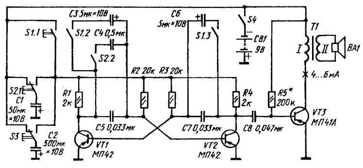
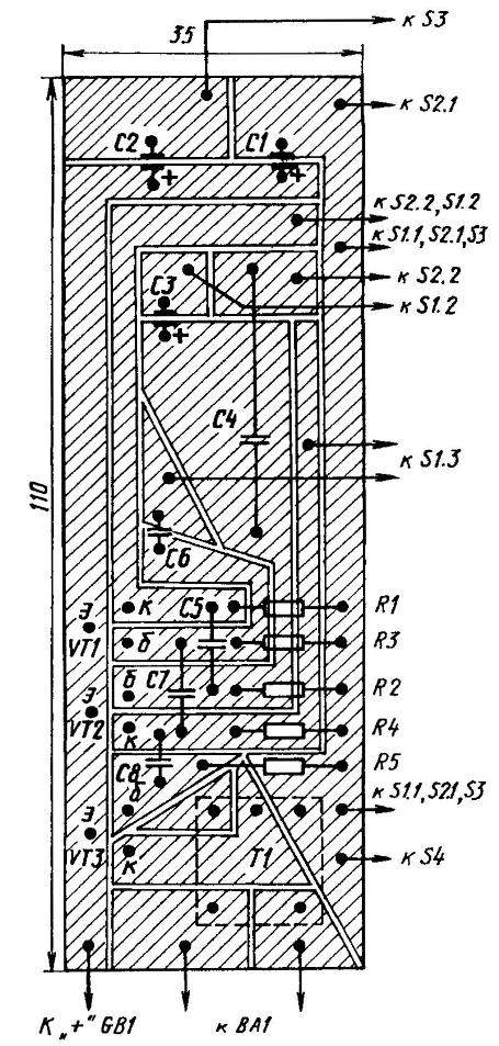
The organization of power supply to the multivibrator in the “rocket” mode is similar - from capacitor C2 through switch s3. In this case, only capacitors C5 and C7 work in the arms of the multivibrator. The sound, starting from a low note, gradually rises to a very high note and seems to disappear into the distance.
Simulation signals are amplified in cascade on transistor VT3, connected according to a common emitter circuit. Its load is the dynamic head BA1 in the collector circuit of transformer T1.
The simulator's power source is a Corundum battery or two 3336 cells connected in series. Can be used network block(adapter). As switches S1-S3, it is better to use buttons or toggle switches with self-return initial position. A knife-type band switch from a portable radio can also be used as S1. Automatic return to the open state will be ensured here if the switch handle is equipped with a spiral spring.
The circuit board of the simulator is made of foil fiberglass laminate. The corresponding oxide capacitors K50-6 or MBM (C4), KLS (C1-SZ, C5-C8), resistors (all of them are MYAT type, with a power of no more than 0.5 W) and other elements of the fundamental circuit are soldered to its “printed” pads. electrical circuit.
It is possible to replace the used parts with their analogues. In particular, instead of those indicated on the principle electrical diagram other transistors from the MP39-MP42A series, as well as (all at once) MP35-MP38A are suitable structures p-p-p. But in the latter option, you will have to reverse the polarity of connecting the power supply and oxide capacitors.
Transformer T1 - output, from radio receivers of the "Selga-404" type. Dynamic head - 0.1 GD-8 or another, having a voice coil resistance of 8-10 Ohms.