When conducting webinars on programming, my listeners once complained about poor sound quality. I had never thought about how important quality sound is before.
After a quick google, I realized that getting high-quality sound, for example, for podcasts, a very difficult task that requires good expensive equipment and good audio processing skills.
The question arose: is it possible to get acceptable sound from a budget microphone for webinars? As it turned out, yes. Below detailed guide how it was done.
As the saying goes: every programmer is a bit of a carpenter at heart.
Formulation of the problem
I had a classic budget microphone called Genius. Here it is.
I believe many of us have such a device. The microphone is normal for its price and tasks. Connected to sound card Sound Blaster Audigy. But there are a number of serious disadvantages:
1. When the microphone is on the table, all the key strokes can be heard while typing on the keyboard. And also any table sounds are transmitted through the base.
2. If you hold the microphone not near your mouth, but as it should be on the table, the sound is as if the webinar is being held in the toilet or a “toilet” sound. Again, holding the microphone in your hands is uncomfortable and you need to somehow secure it near your mouth. If you pick up the microphone and then put it down, the volume of the sound will vary. You will see this in the video below.
3. If you are not lazy and take the microphone in your hands, then all the explosive consonants (for example, “B” and “P”) will directly hit your ears.
How to solve these problems for a modest cheap microphone? Let's start looking.
If you look at how professionals solve these problems, it looks like this:
1. The transmission of sounds and vibrations to the microphone from the base is solved by suspending the microphone on various springs and suspensions. In general, if you search for “microphone suspension”, there are countless options. But in the simplest case it looks like this:

This is a classic vintage radio microphone.
2.
To avoid having to hold the microphone in your hands, there is such a thing as a pantograph. In essence, it is a lamp rod with a microphone at the end.

3. The third problem is solved by the so-called pop filter. Essentially, this is a hoop in which dense fabric, for example, from tights, is stretched. There are also factory solutions.

This rag cuts plosive consonants, and the sound is softer.
All of the above products, incl. You can buy a professional microphone, but it’s more pleasant to do everything yourself. So let's show what we can do.
Sources
As a pantograph, it was decided to use a classic lamp from IKEA, which has served me faithfully for many, many years. The main goal was not to affect the main functionality - to shine!
Test lamp
As a pop filter, we bought a hoop with an outer diameter of 90 mm from a sewing store. It was very funny when an unshaven, two-meter man in camouflage, combat boots, and a storm jacket bought hoops in a sewing store.

Hoop
And it was decided to make the microphone suspension itself using springs from a clamshell, which were purchased at the nearest hardware store.
10 and 20 mm plywood was chosen as the material for production. All manufacturing was done on a jigsaw machine. "Corvette 88".

Jigsaw "Corvette 88".
Honestly, I don’t understand why everyone doesn’t have this thing in their home. An irreplaceable thing in the household. Starting from small things around the house to teaching a child.
Plus we will need two more M6 bolts 40-50 mm long + two washers and a wing for them, two M8x35 bolts, one wing.
Result
Unfortunately, there will be no photo guide for production. Therefore, I will show you the result, and then we will analyze the finished product and look at its drawings. The photographs were taken in the workshop, but there is exactly the same lamp, and there is more light than in the room.
Front view

Assembly type

View from above
Among other things, it provided the possibility of installation on a table as a stationary microphone.

Desktop option

Back view
It so happened that I did it impromptu, practically coming up with a design on the fly. Therefore, most of the drawings are made after production.
Disassembly. Blueprints
What if someone has access to a laser or milling machine and wants to repeat this design. Drawings with dimensions were made especially for such a person. All that remains is to add them to your favorite drawing program.Main stand

Stand with base and pop filter removed

Back view

Stand base
As you can see from the photo, the microphone had to be cut. To do this, you need to disassemble it, unsolder the microphone itself, insert it into the drilled hole, and only then solder and assemble it. The drawing of the three parts is very simple. The base is held simply by friction (the hole is made smaller than the protruding tenon). Hit it with a hammer.


Pop filter
The fabric used is a women's stocking in a hoop. The fingers are simply inserted into the product due to friction. Attached to an outrigger so that the length can be adjusted.

The drawing is simple. But the inner diameter is determined by the hoop found.


Attachment to lamp
The most interesting detail is the attachment to the lamp. It is made of 20 mm plywood. The dimensions are chosen so that the wings can rotate freely. I had to think about this detail.
With one

And the other side
As you can see, the bolt is pressed into a 10 mm piece of plywood, which is already glued to the base.

Fastener assembly
It is curious that the diameter of the lamp is 63mm. Not a very convenient size. So I took the inner radius to 32mm.
One more nuance: it is necessary that the jaws do not fit tightly against each other in order to grip the lamp. Therefore, after the product was made, 1-2 mm was removed from each sponge (size “1-2” in the drawing).

Table base
It's so simple that I didn't even take measurements. To make it heavier, a 20 mm plywood disk left over from mounting the lamp is glued on top. A bolt is pressed into the bottom.
Bottom

Top
For convenience, I present all the drawings on one sheet.

Total
Answering the question: why did I do this? Yes, it was stupidly interesting, and because I can! I thought for a long time about how to attach a microphone to a lamp. And then it came apart, and it turned out like this parsley.
Product in a work interior
I specially made a video of how this microphone sounded and now sounds.
In this video you can evaluate the positive changes for yourself. I didn’t demonstrate the sound of plosive consonants, let it be homework :) I think it’s wonderful budget solution for direct hands and a couple of free evenings.
How to make a simple directional stereo microphone from junk?
I have already described one design of a microphone intended for DSC, but its operation revealed a number of shortcomings, which are described below. So I tried to make a more advanced model.
The result was two different microphones, one monophonic and the other stereophonic.
The most interesting videos on Youtube
 |
 |
 |
 |
Prologue.
My first homemade microphone had a too uneven frequency response due to resonance occurring in the tube. In addition, it only allowed recording monophonic sound. It was decided to build a more advanced microphone model, but as always, do without turning and milling work.
While thinking, several ideas came up for making a slit microphone tube without using machines, or even the tube itself.
Slit microphone tube made of washers.

The slit microphone tube can be made from large diameter washers. If you drill two holes in each washer, you can use two pins to assemble a multilayer sandwich, and adjust the size of the slots using small washers.
This idea, in my opinion, has only one significant drawback. In order to drill holes in each washer with sufficient accuracy, a small jig would have to be made.
Slit microphone tube made of transistor clamps.
If instead of washers you use clamps from old-type transistors, then you won’t have to drill anything at all. All that remains is to collect the handset.

The disadvantage of a pipe assembled from standard clamps from transistors of type P213 ... P217 is its heavy weight. If you use duralumin clamps from transistors like KT801, you can get a fairly light tube. True, in such a tube it will be difficult to place two microphone capsules at once, so for a stereo microphone you will have to look for another solution.
Slit microphone tube made of metal tape.

A slit microphone tube can be made from a narrow metal strip by folding it into a helix on a template of the required diameter. Then the width of the slots can be adjusted by changing the pitch of the screw.
Based on these ideas, I made two microphones - monophonic and stereophonic.
This time I omitted some details regarding the assembly of microphones and the manufacture of parts, since I already covered them in detail.
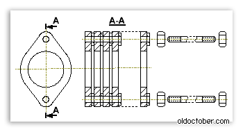
A slot microphone made from transistor clamps.
This is a drawing based on which a slit microphone was made from transistor clamps.

- The clamp for transistors is duralumin.
- Nut – steel, M2.
- Grover washer – steel, M2.
- Hairpin – steel, M2.
- The gasket is cambric.
- Shielded cable – Ø2mm.
- The bushing is rubber Ø11mm.
- Body – medical syringe – 5g.
- Rear wall – medical syringe – 5g.
Assembling a microphone from clamps from transistors turned out to be as easy as shelling pears. Here's what was used for the build.

- Grover washer – steel, M2.
- Shielded cable with 3.5mm Jack connector.
- Helical spiral – solder Ø2mm.
- Velvet.
- Electret microphone capsule – Ø10x7mm.
- Clamp from transistors type KT801, KT602, KT604.
- Medical syringe – 5 g.
- Stud, nut – steel, M2 (studs were made from a bicycle spoke).

In order to do appearance To make it more presentable, I covered the body of the microphone, made from a syringe, with heat-shrink tubing. First I seated the front part, and at the end of the assembly I inserted the cover and seated the tail part.

This is what happened.
Directional slot stereo microphone made of metal tape.
This is a drawing from which a directional stereo microphone was made from metal tape.

- Screw – M1.6x5.
- Nut – M1.6.
- Clamp – steel, S0.3mm. (tin from a tin can).
- Tape – steel, S0.5x8x50mm.
- Screw – M1.6x5.
- Partition – medical syringe 20g.
- Bushing through passage - rubber Ø11mm.
- Weight – solder Ø2mm.
- Krpus – medical syringe 20g.
This microphone required very few parts.

- Shielded mono cable – Ø2mm.
- Shielded stereo cable – Ø3mm.
- Screw – M1.6x5.
- Bushing through passage - rubber Ø11mm.
- Clamp – steel, S0.3mm. (from a tin can).
- Screw, nut, washer – M1.6.
- Weight – solder Ø2mm.
- Electret microphone capsule – Ø6x6mm.
- Medical syringe 20g.
- Tape – steel, S0.5x8x50mm.
- Heat shrink tube – Ø8mm.

In order not to have to paint, I covered the steel tape with heat-shrink tubing, and then rolled it into a helical spiral, item 1, on the body of a 10-gram syringe.
From the body of a 20-gram syringe I made the microphone body, item 3, and the partition, item 2, from the piston of the same syringe.
At this point, you can drill three holes to attach the tube to the body and cut the threads.
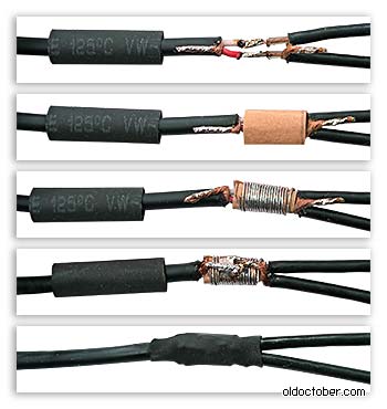
To reduce the length of unshielded wires going to the microphone capsules, I extended the stereo cord with two small pieces of mono cord. The picture shows how it was done. Thick paper is used as insulation.

The microphone body, as in the previous design, was covered with heat-shrink tubing.

Another picture explaining the assembly procedure.

This is what happened.
| Get the Flash Player to see this player. | ||
Here's how it works.
Small details.
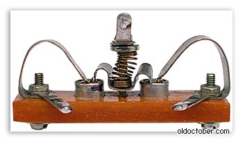
When testing the first pair of microphone capsules, it turned out that their frequency responses differed too much. In anticipation of market day, I even assembled a small stand for testing microphones without the use of soldering. I bought a few more capsules for $0.4 so that I had plenty to choose from. But the very first pair taken from this purchase turned out to be consistent in frequency response. I didn't experiment anymore.
Modern computer technology often has a lot functionality and is equipped to meet the most stringent user requirements. But this is only in a situation where a PC user has purchased one of the latest models and enjoys all the “benefits of civilization.” But this happens when you just need to use a microphone to transmit information, but it is either broken or simply not there. In principle, this is not a problem, because we know how to make a microphone from headphones, and in this article we will also help you deal with this pressing problem quickly and easily. We will also talk about how to make a microphone from scratch.
No soldering
In fact, you can buy such a device in advance if you plan to use a similar function when communicating via a PC. The device will be inexpensive. But if this is not your way, then we will now figure out how to make a microphone for a computer out of headphones. Moreover, this is a fairly simple process that will not take a lot of time and labor! So let's get down to business.
Instructions:
- Plug your headphones into the pink jack. This jack is specifically for a microphone. Of course, it is wrong to plug headphones into the microphone jack, but we will try to use our headphones as a microphone.
- Next, click “Start” - “Control Panel” - “Hardware and Sound”. In the sound section, find “Manage audio devices,” and then click on the “Recording” section.
- Then, in the “Recording” section, you should definitely see a device called “Microphone”.
Important! If this device is missing, it means you did something wrong, try reading these instructions again, doing everything correctly.
- Next, you make this device the “Default Device”. To do this, click once on the device, and then click on the “Default” button.
- Then, in the “Use of device” column, pay attention to the “Use this device (on)” column.
- Next, go to the “Levels” section and move the slider to the very end.
Important! In order to check the functionality of a microphone made from headphones, simply check the box where it says “Listen from this device.”
Important! Problems may arise during the connection and setup process. And so that you don’t have to spend a lot of time looking for solutions, we suggest that you immediately read or save the information from our articles:
Theoretical information about electret microphones
Today, electret microphones have almost completely replaced other microphone designs. This indicates that at a relatively low price they have a smooth frequency response, light weight and high reliability. If miniaturization is extremely necessary, then this property there are no equals to them.
An electret microphone is a classic condenser, one plate of which is made of a fairly thin layer of polyethylene film located on top of a ring. The film is subjected to a process of bombardment with a beam of free electrons, which penetrate a short distance, resulting in the release of a space charge that can persist for quite a long time. This type of dielectric is called an electret, and it is for this reason that the microphone is called “Electret”. A thin layer of metal is also applied to the film, which is used as one of the electrodes.
Do-it-yourself electret microphone - manufacturing secrets
To work you will need:
- Electret microphone capsule. By and large, it’s easy enough to get it out of an old Chinese tape recorder or an outdated landline telephone.
Important! The larger the capsule diameter, the greater the low frequency range.
- A piece of flexible thin wire.
- Regular 3.5 mm jack plug.
- Plastic body from a syringe.
- A small paper clip, as well as a piece of foam rubber.

So, let's begin the process of assembling a microphone for a PC with our own hands:
- Cut off a small amount of the syringe body from the side where the needle itself is attached (approximately around the 1 gram pointer) using a utility knife.
- Remove unnecessary markings from the surface of the syringe body with acetone or another solvent.
- Sand the cut edge with light grit sandpaper.
- Insert the shielded flexible wire into the hole and make a small knot.
- After this, solder the capsule so that the braid of the shielded cable is connected together with the metal case.
- Insert the capsule into the body, and then click the place where the needle was previously placed using the tab of a standard paper clip.
- On the second side of the flexible shielded wire, solder a 3.5 mm jack plug, with the right and left channels connected together.
By and large, the microphone is already completely ready, but let’s make another aesthetically important detail from foam rubber - a windproof cap:
- Cut a square piece of foam using a knife.
- Using absolutely any sharply sharpened tube, make a neat cylindrical depression by rotating the tip from the inner surface of the tube.
Important! Sections from used broken telescopic antennas, which you can sharpen with a scalpel, are excellent for these purposes.
Without computer microphone it’s very difficult to get by now, you can’t use it without it voice search, you won’t be able to chat with a friend via video call. However, not all computers have built-in microphones, and moreover, they often do not have very good sensitivity. You can solve this problem quite simply - assemble the microphone yourself.
Scheme
The circuit is extremely simple, containing only two resistors, two capacitors, a transistor and an electret microphone capsule. Almost any low-power transistor can be used n-p-n structures, for example, KT3102, BC547, BC337. An electret microphone can be obtained, for example, from a broken headset or handset, or you can buy it at a radio parts store. The sensitivity of the microphone will greatly depend on this element, so it is advisable to take several and check which one is best suited. The advantage of this circuit is that it uses phantom power. Those. sound signal transmitted over the same wires as power. If you take a voltmeter and measure the voltage at the microphone input of your computer, it will be about 3-4 volts. When connecting the microphone circuit, this voltage should drop to a level of 0.6-0.7 volts, thus, an external power source will not be needed and unnecessary wires will not be in the workplace.
Circuit assembly
The circuit contains a minimum of parts, so it can be assembled by hanging installation. But, sticking to tradition, I etched a miniature printed circuit board. The paths can even be drawn with a marker or nail polish. A few photos of the process:

Download the board:
(downloads: 206)
A microphone capsule is soldered on one end of the board, and a shielded wire on the other. Please note that the wire must have a shield, otherwise the microphone will produce terrible noise. The braid of the wire is soldered to the negative, and the two inner cores are connected and soldered to the output of the circuit. It is imperative to maintain the polarity of the microphone capsule, otherwise the circuit will not work. One of its outputs goes to minus, and the second to plus. Determining the polarity is very simple - you need to ring the terminals with the metal body of the capsule. The terminal that connects to the housing is negative.


Microphone assembly
For ease of use, a board with soldered parts must be placed in a suitable housing. Because Since the board has a narrow, elongated shape, you can use an ordinary ballpoint pen as a body. To do this, you need to remove the writing rod from it and check whether the board is the right width. If the circuit is assembled by hanging installation, then it can be given any shape and there will be no problems with capacity. In addition to a pen, any elongated object will work well, be it a marker or a simple plastic tube.Preamble:
“Boney-M” (a very famous VIA at one time) came to Moscow on tour. At the airport, as usual,
the luggage with the equipment was “loved” and the reverb (the device that makes the echo) just disappeared.
Well, there’s nothing to do, let’s go get a new one at the Mitinsky radio market. Check before purchasing.
To the microphone:
- Once.
From the speakers:
- One, one, one...
Have taken.
Concert. They start singing:
- Sunny...
From the speakers:
- One, one, one...
Actually the plot itself is below.
My little one calls me from a broken tank and complains that he has big problems with the microphone on his laptop, they can’t hear him, etc. and so on. and that because of this it is impossible to shout commands in a tank battle - in short, I advised him to study the language of the deaf and dumb...
However, my father’s feelings after drinking beer somehow reached my conscience and I had to think, could the Chinese, with their sophisticated minds, come up with a tiny USB microphone? Of course, it is known that Chelyabinsk men shout directly at the USB - but still... It turned out that there is such a miracle - then as usual: cart, payment, shipment, waiting, receipt. 
The microphone itself is created in the now fashionable form factor “a la semi-circular fitulence”. 
The connection happened without any problems or pitfalls, I tried to swear at it and got the same thing in response. This is not a Gogol translation for you, which translates “fuck you” as “fuck you” - that is, there is no distortion of the voice, there is also no obvious acoustic connection - although it tries to “whistle”, the sensitivity is normal - there is no need to shout. 
Otherwise, of course, you can read on the packaging how good it is - but everything written there is an absolute lie.
1) connects via USB and blah blah blah - HALF-TRUE
2) presence of noise suppression filters HALF-TRUE
3) presence of LED FALSE
4) presence of a stand FALSE
The specifications are probably close by an order of magnitude, but for such a microphone it is unlikely (or rather for its physical dimensions) and it is written that there is another 8" cable - an OBVIOUS LIE 
However, this was not important for me - the baby just needs to hold out until the holidays, and then with unwashed hands I will climb into the laptop and bring my native microphone into use. In a word, I recommend it for purchase.