The article provides a general overview of the technology for laser scanning of objects in space, and discusses devices that implement this technology and are used in mobile robotic systems.
LIDAR TECHNOLOGY OVERVIEW
The term LIDAR (from the English Light Detection and Ranging) refers to radar systems operating in the optical range and using a laser as a radiation source. Often in foreign sources you can find similar terms - LADAR (Laser Detection and Ranging) and Laser Radar. In mobile ground robotic systems and unmanned aerial vehicles (UAVs), this technology plays a very important role: it is used to automatically construct a three-dimensional map (scene) of the surrounding space and the spatial orientation of the device. There are different versions of LIDAR systems, but in general they all include the following key elements that determine the principle of operation of the system: ● photon source (most often a laser);
● photon detector;
● timing circuit;
● optical transceiver part.
Time-of-flight (ToF) LIDAR systems use short pulses of laser radiation, accurately recording the moments of their transmission and reception of responses (reflected signals) in order to calculate the distances to objects in the surrounding space or on the surface of the earth (for example, when topography from a UAV). After combining a series of such measurements with information about the location and orientation of the vehicle, the resulting three-dimensional scene of the region of interest is created. Most often, this scene is stored as an array of (x, y, z) coordinates called a point cloud.
Although there are many LIDAR devices for different applications, they all consist of a similar set of functional units (see Fig. 1), such as:
● distance measurement subsystem (laser transmitter and receiver);
● scanning subsystem;
● positioning and orientation subsystem;
● control system;
● data storage.
DISTANCE MEASURING SUBSYSTEM
The fundamental differences between individual LIDAR devices are the implementation of the distance measurement function. The most important component of the LIDAR system - the distance measurement subsystem - consists, in turn, of such internal subsystems as a laser transmitter and an electro-optical receiver. The laser transmitter emits energy in the form of a focused beam, which, before exiting the device, passes through a number of conversion components: a transceiver switch, beam expanders, output telescopic optics, and others. The LIDAR system can be used Various types lasers, but most often a solid-state Nd:YAG laser is used, the active medium of which is yttrium aluminum garnet (Y3Al5O12) doped with neodymium ions. Laser scanning rangefinders operate at various wavelengths, but the most commonly used are the following:
● 1064 nm (near infrared range) – for topographic scanners;
● 532 nm (green) – for bathymetric (depth-measuring) scanners;
● 600–1000 nm – for ground-based devices intended for commercial use;
● ∼1500 nm – for ground-based scanning systems used for scientific purposes.
The choice of laser emitter wavelength depends on a number of factors:
● reflective properties of scanned objects;
● environmental characteristics;
● sensitivity of the detector used;
● the required degree of safety for the eyes;
● requirements for the design of the device.
In addition to the wavelength of the radiation, the laser power must also be taken into account. An electro-optical receiver receives the energy of a laser beam reflected or scattered by a target and focuses it onto a light-sensitive detector using input optics.
Methods for determining distance
The recorded values of the moments of transmission and reception of the laser beam are used to calculate the time spent by the light in transit, and, consequently, the distance to the object that reflected the beam. A LIDAR system typically uses one of two modes to determine the distance measurement method: pulsed mode or continuous wave mode. In pulse modulated systems, also known as time-of-flight systems, a laser emits single pulses of light with high frequency following. The time elapsed from the moment the pulse signal is emitted until the response returns to the receiver is measured. The distance to the point on the surface of the object at which the laser beam was reflected can be calculated using the formula: D = 0.5 × c × t, (1) where c is the speed of light, t is the total time it takes light to travel to the point of reflection and back (roundtrip), D – the required distance to the reflection point. In continuous wave systems, the laser emits a continuous signal, which is then applied with sinusoidal amplitude modulation. In this case, the time it takes light to travel the full path from the transmitter to the receiver will be directly proportional to the phase shift in the emitted and received signals: (2) where ϕ is the phase shift, T is the signal period. After determining the time t of passage of the beam, the distance D, as in the first case, is calculated using formula (1). Multi-tone sinusoidal modulation can be used to reduce uncertainty. Continuous wave systems also use an alternative method - linear frequency modulation. In such systems, the transmitted and received signals are mixed, and a coherent receiver is used to demodulate and obtain the information contained in the carrier frequency. It should be noted that in equations (1) and (2) it is assumed that the detector is stationary during time t. For cases with a moving detector, it will be necessary to make appropriate adjustments to the equations.
Detection methods
Typically, LIDAR systems use two detection methods: direct and coherent. In direct detection, the receiver converts the signal directly into a voltage or current that is proportional to the incoming optical power. Receivers may include avalanche photodiodes and photomultiplier tubes. LIDAR detectors can also operate in photon counting mode. In this mode, the detector is capable of detecting even a very small number of photons, and in Geiger counter mode it becomes sensitive even to individual photons. The receiver electronics measure the generated current, corrected for the time of flight of the photons in the receiver, resulting in a direct measurement of the moment at which the optical response is received. With coherent detection, the resulting optical signal is mixed with a local oscillator via a local oscillator, and only then is focused on a photosensitive element. When mixed, the information is converted into a narrow-band signal, which reduces noise compared to the direct detection method, which uses an optical filter.
Traveling beam and array
It is important to note that the described ranging and detection methods require different receiver geometries. In general, most commercial LIDAR systems operate on the "traveling beam" principle, where for a single emitted pulse one or more (typically 2 to 5) distance values are recorded for optical signals returning along the same line of sight (multiple returns ). For the next pulse, the targeting subsystem changes the direction of the line of sight, and then several distance values are recorded again. This method, the point scanning method, is typically used in LIDAR systems operating in a linear mode, in which laser energy is focused on a small area of the surface being examined, and a sufficiently strong reflected signal is required to record the response and calculate the distance. However, there are also LIDAR systems that use laser light to illuminate a large surface area. However, they are equipped with a frame-by-frame matrix detector to measure distance values for each pixel in the array. These vertical scan systems require low reflected signal strength. They record hundreds or even thousands of distances for the emitted pulse.
SCAN SUBSYSTEM
In cases where it is necessary not only to determine the distance to an object, but to provide an overview of the target area, the LIDAR system must take measurements at multiple points. To build a scene of the target area of space, a combination of the movement of the LIDAR device as a whole and the operation of the scanning subsystem through which the emitted optical signal passes is used. A common implementation option for the scanning subsystem is based on the use of a swinging mirror. Consistent change in the direction of the line of sight along which the optical signal is emitted is carried out using a movable mirror. This mirror rotates through a limited angle (viewing angle) around an axis lying on its plane and, as a rule, parallel to the direction of movement of the device. Swinging the mirror allows you to scan the target area of space and form a scene of the required width, determined by the angle of swing of the mirror (see Fig. 2).
 Rice. 2. Oscillating scanning system
 mirror
A subsystem based on an oscillating mirror creates a sinusoidal sweep. In this case, the swing frequency is inversely proportional to the specified viewing angle (scene width). The main disadvantage of this scanning method is the inconsistent speed of the mirror. Twice during the operating cycle the mirror must slow down, come to a complete stop, reverse direction and then speed up again. As a result, measurements taken at a constant frequency create a scene with an uneven density of points (fewer points in the middle of the scan strip and more at the edges). The laser beam scanning subsystem using an oscillating mirror is used, in particular, in laser scanners from Leica and Optech. Alternative way scanning is based on the use of a rotating prism. In such a scanning subsystem, a multifaceted prism with mirror faces continuously rotates around its axis of symmetry. The laser beam moves from one face of the prism to the other in an abrupt manner, as a result of which the array of points formed during the movement of the device consists of a number of parallel lines (see Fig. 3).
 Rice. 3. Scanning system with rotating
 prism
This option does not have the disadvantages of a swinging mirror, but it is more difficult to implement and with regard to processing measurement results. Rotating prism LIDAR systems are produced by the Austrian company Riegl. The third variant of the scanning subsystem uses a rotating mirror. The axis of rotation in this version is located almost perpendicular to the surface of the mirror (see Fig. 4).
 Rice. 4. Scanning system with rotating
 mirror
Due to the deviation of the mirror surface from the plane perpendicular to the axis of rotation, a scan of the reflected laser beam is formed in the form of an elliptic curve. The advantage of the method is that each point in space is scanned twice. At the same time, elliptical scanning significantly complicates the processing of scanning results, since processing double measurements is a very complex task. In addition, since points in the same area are obtained from different positions (as the system moves and changes orientation in space), the point cloud obtained in this way may contain a large amount of “noise”. Examples of systems that use laser beam scanning using a rotating mirror are Leica AHAB DragonEye scanners. As an alternative to mechanical sweeping, some LIDAR systems now use a fiber optic subsystem to direct the laser beam to the target area. This method achieves a more stable scanning geometry due to fixed connections between the fiber optic channels and other optical channels of the device. The laser beam is directed using a fiber optic beam, and the scanning direction for each pulse depends on which fiber optic channel it is emitted from. A similar beam system is used in receiving optics (see Fig. 5).

POSITIONING AND ORIENTATION SUBSYSTEM
For the practical use of information obtained using scanning laser rangefinders, just an array of distance values from the device to objects and relative scanning angles is not enough. Reliability of data about the surrounding space (obtained in the form of a three-dimensional point cloud or a two-dimensional image with distance data) can only be achieved if for each point the absolute values of the position and orientation of the LIDAR system carrier platform in space are measured at the moment the response from the pulse is received. For such measurements, an orientation and positioning subsystem is used. This subsystem includes two main components: a global positioning system receiving module (GLONASS or GPS) and an inertial navigation unit (IMU). GPS receiver data is used to record the carrier platform's locations in certain moments time. Of the many existing methods for clarifying GPS coordinates, LIDAR systems usually use differential post-processing of a signal from a stationary base station or real-time differential updates. To obtain more accurate data sets, strict restrictions are placed on the placement of the base station relative to the laser rangefinder platform. The orientation of the platform is measured using an inertial measurement device unit that uses gyroscopes and accelerometers. GPS and IMU data are recorded while driving platforms and combined (usually during a data post-processing step).
CONTROL SYSTEM (SYSTEM CONTROLLER)
To generate a point cloud, all subsystems that make up a LIDAR system must work together. The quality of the data obtained directly depends not only on the parameters of each subsystem, but also on the consistency of their operation. Setting the sensor parameters and monitoring the operation of the subsystems is carried out by the system controller of the laser rangefinder.
DATA STORE
The final LIDAR data are files containing GPS and IMU coordinates, measured distances, and sometimes information from other subsystems. Because LIDAR systems can generate very large amounts of data, the system includes a storage device to which the data is stored immediately after collection.
PRACTICAL EXAMPLE: VELODYNE HDL-64E
As an example, consider the HDL-64E high-resolution laser scanning rangefinder device manufactured by Velodyne. It is this 64-beam LIDAR with 3D scanning that is installed on self-driving cars developed by Google. The laser rangefinder became one of the key components that made it possible to make the car truly autonomous.

The Velodyne device, installed on the roof of a self-driving car (see Fig. 6), generates a detailed three-dimensional map of the surrounding space. The on-board computer combines LIDAR measurement data with high-resolution maps, generating various data models that allow the robotic vehicle to move independently, avoiding obstacles and complying with traffic laws. The HDL-64E rangefinder model has 64 emitter-detector pairs, which provide equally spaced 26.5° sector fields of view. To provide a 360-degree azimuth view, the entire optical unit is mounted on a rotating base (see Fig. 7) and rotates at 600 rpm.
 Rice. 7. Appearance of the laser rangefinder
 HDL-64E
If necessary, this frequency is adjustable in the range of 300…900 rpm by sending a simple text command via serial interface. The same serial port can be used to update the scanner firmware. The Velodyne rangefinder has a maximum distance measurement range of up to 120 m with an error of no more than 2 cm. Regardless of the rotation speed of the optical unit, the device constantly generates a large amount of data - 1 million points per second, which corresponds to a horizontal angular resolution of 0.05°. The device is statically and dynamically balanced, minimizing the effects of vibration and providing a stable image of the scene. Each HDL-64E rangefinder laser emits a 5 ns optical pulse (at 50% amplitude with a maximum peak power of 60 W). The high voltage required to create a peak current in the emitter of 30 A is generated by the flyback converter circuit, which allows it to be used to power a laser installation low voltage . The output laser beam is focused by lenses. When hitting a target, part of the radiation is reflected back in the direction of the source. This reflected light passes through a separate lens system and a UV filter necessary to reduce background optical illumination (increase the signal-to-noise ratio). The receiving system lenses focus the reflected radiation onto an avalanche photodiode, which generates an electrical signal proportional to the optical intensity. The laser and avalanche photodiode are adjusted at the factory to provide maximum sensitivity while minimizing signal crosstalk, thus forming the most efficient emitter-detector pair. In accordance with the strength of the reflected signal detected by the avalanche photodiode and the amplifier circuit, the system changes the amplitude of the laser pulse, maintaining the minimum required radiation level. This automatic adjustment of laser power, firstly, reduces the heating of the optical unit and increases its reliability, and secondly, prevents the detectors from entering saturation mode. Otherwise, if the detector receives too much optical energy, a saturation mode would occur, from which the detector requires significant time to exit (if it exceeds the pulse repetition period, this inevitably leads to distortion of the detected signal). Thirdly, if the signal level is comparable to noise, which complicates its detection, the system automatically increases the laser power level. This can happen, for example, when approaching the sensitivity threshold (120 m) or when there is a weak reflection from a black matte surface. The output signal is amplified and transmitted to an analog-to-digital converter with a sampling frequency of 3 GHz. The digitized signal from the detector is then transmitted to a digital signal processor (DSP), which uses its own algorithm to analyze the data and determine the signal return time. The use of short optical pulses in combination with high-frequency signal processing provides greater resolution of the system. The emitter-detector pairs are divided into two groups of 32 lasers. One group is located at the top of the module and is aimed at the upper half of the field of view, and the second group, located under the first, is aimed at the lower half of the field of view. Because the upper optical unit is designed to measure longer distances, the angular distance between optical pulses is greater than that of the lower unit, which measures shorter distances. The device provides data to the user via a standard 100BaseT Ethernet port. Information is continuously transmitted in the form of frames. The frame generation frequency is equal to the rotation frequency of the optical unit (at 600 rpm – 10 Hz). The amount of data transferred per second can contain more than a million points. The data packets contain information about the distance and radiation intensity for each emitter-detector pair, as well as the corresponding angular coordinate. This data can be collected using a standard Ethernet packet acquisition utility such as Wireshark, and visualized in a computer program such as Velodyne Digital Sensor Recorder. The resulting data can also be processed by an autonomous navigation system to create a score map, which can then be used to identify obstacles, find the optimal route and ultimately perform calculations related to steering, braking and acceleration. Figure 8 shows an example data frame from an HDL-64E device captured using the Velodyne Digital Sensor Recorder application. A white dot is visible near the center of the image, indicating the position of the sensor. For each emitter-detector pair, the generated point cloud is represented in a separate color. The spatial representation of data is formed by combining two-dimensional point clouds. When the module rotates, a set of points from one emitter-detector pair forms a continuous circle on a flat surface. The example given refers to the option of installing a rangefinder on the roof of a truck cab, so in the image below the white dot there is a dark area - the body. As you can see in the picture, there are two vehicles in front of the truck: another truck trying to turn left and a car crossing the intersection. In addition, a guardrail, dirt, and trees can be seen behind the car in the image. To the left and right of the sensor, wavy areas are visible, corresponding to the road fence and sidewalk and highlighting the roadway in the field of view. We can see bushes along the sidewalk. The data obtained also makes it possible to determine the traffic situation behind the sensor - the image shows a vehicle behind the truck. It is important that there are no breaks in the circular data (around the truck) in any of the point clouds. This fact shows that the laser pulse repetition rates for the upper and lower rangefinder units are configured correctly. If the pulse repetition rate were lower than required, then each of the circles would consist of dotted lines. Blank areas in the image occur due to obstacles in the optical path that do not allow data to be obtained about the space behind them (shading effect). For example, this is how a black stripe appears behind the back of a truck. It should be noted that the LIDAR device can also be mounted at an angle of 90° to the vertical axis to change the field of view. This installation scheme can be used in geodetic and cartographic applications. The considered Velodyne HDL-64E laser rangefinder belongs to class 1M, that is, it is considered safe for the eyes. The sensor is housed in a waterproof housing, remains operational at extreme temperatures and is optimal for use in cars. Basic specifications devices are shown in the table.
An optical sensor is used - lidar (lidar from Light Detection and Ranging, literally light detection and ranging). The sensor uses electromagnetic waves in the infrared range, with the help of which the distance to the object (vehicle) in front is determined, as well as its speed. Lidar can be used to detect moisture particles in the atmosphere and road markings.
In terms of its functions, lidar acts as an alternative to automotive radar, which is why it has another name laser radar. The advantages of lidar are its smaller size (can be installed anywhere), high angular resolution (about 180°), significant range (up to 250 m), and relatively low cost. Infrared rays have been proven to be safe for the human eye.
At the same time, laser radar is sensitive to changes in road topography (rays can be reflected from the road surface and distort information). The effectiveness of the lidar decreases in bad weather conditions (rain, snow, fog), as well as when the sensor is dirty.
The leading lidar manufacturers are Denso, Continental, Siemens, and Hella. Laser radar is used in the adaptive cruise control system of Nissan and Toyota, in the active night vision system of Mercedes-Benz, Toyota, and in the automatic emergency braking system of Volvo (City Safety system).
To increase the efficiency of object detection, lidar can be used in conjunction with radar or a car video camera. Automatic vehicle control systems being developed also cannot do without lidar.
Lidar device
The design of an automotive lidar includes the following elements: transmitter, modulator, receiver, optical element, amplifier, analog-to-digital converter and microprocessor.
The role of the transmitter is performed by a laser diode, which serves to transmit infrared radiation. Infrared radiation is modulated in a modulator, which changes its intensity if necessary. Depending on the type of modulation, continuous and pulsed lidars are distinguished. Pulse modulation of infrared radiation is more advanced. To increase the measurement efficiency, multi-pulse technology is used (transmitting several pulses simultaneously).
The light pulse and then its reflections pass through the optical element. The reflected pulse is received by a photodiode, where it is converted into an electrical signal. Next, the signal is amplified by an amplifier, converted to “digital” using an ADC (analog-to-digital converter), and then processed by a microprocessor.
Despite the differences in design, the operating principle of lidar is similar to radar. Lidar sends infrared light to the target. The light is partially reflected from the target and partially scattered. The reflected pulse returns back, where it is perceived by a photodiode. The current across the photodiode is proportional to the exposed light. Based on the received digital signal, the processor determines the distance to the vehicle ahead and its speed.
High horizontal and vertical resolution of the lidar is achieved through a multi-beam transmitter configuration, which is achieved in several ways - using a rotating mirror, moving the transmitter.
Owners of patent RU 2575766:
The invention relates to the field of laser ranging and quantum electronics and is intended for use in laser ranging systems and complexes for the purpose of detecting moving objects and determining the parameters of their movement, including spatial coordinates and speed of movement. The proposed device can also be used in laser space communication systems to communicate with a spacecraft in near or deep space, as well as to communicate with a spacecraft when landing on Earth through a layer of plasma surrounding the spacecraft. The proposed device belongs to the class of laser systems that use the laser heterodyning method when receiving and processing laser ranging signals. This method of receiving laser signals is known and studied in the scientific literature, where some advantages of this method compared to the method of direct photodetection of laser signals are noted. However, a number of shortcomings in the practical implementation of laser heterodyning did not allow full use of the potential capabilities of this method for creating effective laser ranging systems for wide application. The main technical disadvantage of this laser heterodyning method is the need for high-precision matching of the wavefronts of the received laser radiation (LR) and the laser heterodyne radiation on the photosensitive site of the receiving photodetector. The monograph on page 156 shows that in the presence of an angular mismatch of about 12 arc minutes of the received and heterodyne laser radiation, the signal at the output of the photodetector - photomixer at an intermediate frequency decreases five times compared to the signal level at zero angular mismatch. This dependence of the output signal level leads to strong fluctuations and periodic complete loss of the output signal, a decrease in the probability of detecting observed objects and a decrease in the efficiency of the laser receiving system in real conditions of tracking fast moving objects.
A laser range finder with a heterodyne processing circuit is known according to a German patent (Z. No. 2819320), containing a laser, a clock pulse generator, a transceiver optical system, a laser local oscillator, an optical mixer of received laser radiation with local oscillator radiation, a photodetector, a block of amplification and processing of intermediate signals. frequencies from the output of the photo detector, memory and information processing unit. The disadvantages of this device include the low efficiency and low detection ability of the device when operating in real conditions of observing moving objects in the presence of various background noise at the input of the receiving optical system. These disadvantages are due to the significant dependence of the level of the intermediate frequency signal (photomixing signal) on the matching of the angles of incidence on the site of the photodetector of the local oscillator radiation and the received laser radiation. When tracking a rapidly moving object, the angle of incidence of the received laser radiation is subject to continuous changes, which leads to significant fluctuations in the level of the intermediate frequency signal at the output of the photodetector and a decrease in this level, as a result of which the probability of correct detection of the object decreases, the accuracy of determining the parameters of the object's movement and efficiency decreases. operation of the entire device as a whole.
A known laser locator with a heterodyne method for receiving laser signals developed in the USA is given in the book Laser Ranging on page 230, containing a transceiver telescope, a laser transmitter with laser amplification stages, a laser local oscillator, a photoreceiving unit with an amplification unit, a master laser oscillator, a second photodetector , frequency measurement and control unit, information processing and control unit. The disadvantages of this complex include low operating efficiency with significant complexity of the complex. The complex lacks means to ensure continuous matching of the angles of incidence of the local oscillator laser radiation on the photoreceiving unit and the received laser radiation reflected from the accompanied fast moving object. As a result of possible changes in the angle of incidence of the received laser radiation on the photodetector site in the operating mode of detection and tracking of an object, a dynamic mismatch of the indicated angles of incidence occurs, leading to strong additional fluctuations in the level of the intermediate frequency signal and to a complete loss of the signal and failure of detection and tracking of the object. This complex uses a system for adjusting the generation frequency (wavelength) of the radiation of the master laser oscillator (laser transmitter). However, the used method of adjusting the laser generation wavelength using an intracavity piezocorrector does not have the required accuracy, which further reduces the accuracy and efficiency of the laser locator.
As a prototype, a laser locator with a pulsed radiation mode was chosen, the diagram of which is given in the book Laser Ranging on page 245. This laser locator contains a receiving and transmitting telescope with a guidance (scanning) unit, a lens, a photoreceiving unit, a signal processing and control unit, a laser transmitter, laser local oscillator, frequency measurement unit, fixed attenuators - radiation absorbers, beam splitters. The disadvantages of this device include the low efficiency of work on real moving objects, as well as the low probability of correct detection of a moving object due to the presence of a mismatch in the angles of incidence of the received laser radiation and the local oscillator radiation on the site of the photodetecting unit in the mode of detection and dynamic tracking of moving objects.
The achieved technical result is the following: reducing the dependence of the output signal level on changes in the angle of arrival of the received laser radiation (LR), increasing the efficiency of the laser ranging system in conditions of detecting and tracking moving objects and in the presence of strong background flare, increasing the probability of correct detection of observed objects, implementation of stable laser communication with a spacecraft through a layer of surrounding plasma upon entry into the dense layers of the atmosphere during the landing of the spacecraft on Earth.
The new technical result is achieved as follows.
1. In a laser locator containing a telescope with a guidance unit installed sequentially on the first optical axis, a first lens, a first photoreceiving unit, the output of which is connected to a block of spectral filters, the outputs are connected to the control unit, a laser transmitter, a laser local oscillator and a frequency measurement unit, output laser transmitter is optically connected to the telescope and, through translucent and reflective mirrors, to the first optical input of the frequency measurement unit, the second optical input of which is optically connected through a translucent mirror to the optical output of the laser local oscillator, the control inputs of the laser transmitter, laser local oscillator and the output of the frequency measurement unit are connected to the control unit, a first controlled attenuator, a first laser radiation frequency shifting unit, a first laser radiation scanning unit, the optical output of which is optically connected through a reflective and two translucent mirrors to the optical input of the first photodetecting unit, a second controlled attenuator, are introduced in series optically. a second block for shifting the frequency of laser radiation, a second block for scanning laser radiation, the optical output of which is optically connected through two translucent mirrors to the optical input of the first photoreceiving unit, the optical inputs of the first and second controlled attenuators are optically connected through translucent mirrors to the optical output of the laser local oscillator, optically connected in series a third controlled attenuator, a third laser frequency shifting unit and a third laser radiation scanning unit, sequentially installed on the second optical axis, optically connected to the acousto-optical modulator with the control unit, a second lens, a first translucent mirror, a controlled spatial filter, a third lens, a second translucent mirror, a second a photoreceiving unit, the output of which is connected to the input of the second block of spectral filters connected to the control unit, the optical input of the acousto-optical modulator is optically connected through a reflective mirror and a translucent mirror with the optical output of the laser heterodyne, the optical output of the third laser radiation scanning unit is optically connected through a reflective mirror and the second a translucent mirror with an optical input of the second photodetecting unit, the optical input of the third controlled attenuator is optically connected to the optical output of the laser local oscillator, a third photodetecting unit, the optical input of which is connected through the first translucent mirror to the optical output of the second lens, and the output is connected to the control unit of the photodetecting unit connected to the control unit, the first and second remote mirrors, mechanically connected to the movement unit, the control input of which is connected to the control unit, a dynamic spectral filter, the optical input of which, through the first scanning mirror and the first remote mirror, is optically connected to the optical output of the telescope, and the optical output of the dynamic spectral filter through the second scanning mirror and the second remote mirror is optically connected to the optical input of the first lens, the control electrodes of the first and second scanning mirrors are connected to the scanning mirror control unit, the input of which is connected to the control unit, the control input of the dynamic spectral filter is connected to the control unit, external a corner reflector optically connected to the optical input of the telescope and mechanically connected to a moving block of the corner reflector connected to the control unit, a fourth controlled attenuator optically connecting the optical output of the laser transmitter to the telescope, control inputs of controlled attenuators connected to the control unit, control inputs of frequency shift units laser radiation and laser radiation scanning units are connected to the control unit.
2. The laser radiation frequency shift unit contains an optically connected input diaphragm, an acousto-optic cell with a control unit, a first lens, a point diaphragm, a second lens and an output diaphragm mounted in series on the optical axis, while the control electrode of the acousto-optical cell is connected to the acousto-optical cell control unit.
3. The laser radiation scanning unit is made on the basis of an acousto-optical cell in which ultrasonic waves are excited, ensuring a change in the direction of propagation of laser radiation.
4. The dynamic spectral filter is made on the basis of an acousto-optical cell in which ultrasonic waves are excited and interact with the received laser radiation passing through the cell.
5. The laser transmitter and laser local oscillator are made on the basis of laser generators with the ability to adjust the wavelength of the generated laser radiation.
In fig. Figure 1 shows a block diagram of a laser locator. In fig. Figure 2 shows a block diagram of the laser frequency shifting unit. In fig. 3 and 4 show the experimentally obtained spectra of received information signals generated in the laser locator system, and FIG. Figure 5 shows the spectrum of background interference radiation.
In fig. 1 numbers indicate the following elements of the laser locator.
1. Telescope.
2. Guidance block.
3. First lens.
4. First photodetector unit.
5. Block of spectral filters.
6. Control unit.
7. Laser transmitter.
8. Laser local oscillator.
10. First block of laser radiation frequency shift.
11. First laser radiation scanning unit.
12. Second block of laser radiation frequency shift.
13. Second laser radiation scanning unit.
14. The first controlled attenuator.
15. Second controlled attenuator.
16. Third controlled attenuator.
17. Third block of laser radiation frequency shift.
18. Third block of laser radiation scanning.
19. Acousto-optical modulator.
29. Acousto-optical modulator control unit.
20. Second lens.
21. The first translucent mirror.
22. Controlled spatial filter.
23. Third lens.
24. Second translucent mirror.
25. Second photodetector unit.
26. Second block of spectral filters.
27. Third photodetector unit.
28. Control unit for the third photodetector unit.
29. Acousto-optical modulator control unit, pos. 19 (listed above).
30. Dynamic spectral filter.
31. Scanning mirror control unit, pos. 35 and 36.
32, 33. First and second remote mirrors.
34. Moving block.
35. First scanning mirror.
36. Second scanning mirror.
37. Remote corner reflector.
38. Block for moving the corner reflector.
39. Translucent mirror.
40. Reflective mirror.
41, 42, 43, 44. Translucent mirrors.
59. Reflective mirror.
45, 46. Reflective mirrors.
47, 48. Translucent mirrors.
49. Reflective mirror located in the optical shadow of the counter-reflector
50 telescope pos. 1.
58. Fourth controlled attenuator.
59. Reflective mirror.
In fig. 2 the following elements are indicated.
51. Input diaphragm.
52. Acousto-optical cell.
53. Acousto-optical cell control unit.
54. First lens.
55. Spot diaphragm.
56. Second lens.
57. Output diaphragm.
60. Piezo element.
The operating principle of a laser locator is as follows.
Laser transmitter 7 generates pulses of laser radiation that illuminate the observed object. The telescope 1, using the guidance unit 2, is directed to a certain specified area of the observed space, in which the location and movement of the detected and observed object is possible. The laser radiation reflected from the object is captured by the telescope 1 and from the output of the telescope using the first lens 3 is focused on the photosensitive area (optical input) of the first photoreceiving unit 4. In this case, a corner reflector 37 used in the mode is removed from the optical path of the telescope 1 using the moving unit 38 testing and setting up the laser locator. At the same time, remote mirrors 32 and 33 are removed from the optical path of the receiving channel of the laser locator using the moving unit 34. In this case, the dynamic spectral filter 30, used in case of strong external background noise, is turned off from the optical path. The controlled attenuator 58 is switched to the standard full transmission mode of the laser transmitter 7 radiation (zero attenuation mode). Laser radiation from the output of the telescope 1 goes directly to the optical input of the first lens 3, which then focuses the received laser radiation reflected from the object onto the photosensitive pad of the first photoreceiving unit 4. At the same time, laser radiation generated by the laser local oscillator 8 enters the photosensitive pad through translucent mirrors 42, 43 and two branches of changing the parameters of laser heterodyne radiation, pos. 14, 10, 11 - first branch and pos. 15, 12, 13 - second branch. These two branches form two heterodyne laser radiation, with the help of which the first photoreceiving unit 4 implements the mode of heterodyne laser reception (photomixing) of the received laser radiation at two different frequencies of heterodyne laser radiation. Accordingly, at the output of the photodetector unit 4, two electrical signals are generated at two different intermediate frequencies f 1 and f 2, which are then supplied to the inputs of the first block of spectral filters 5, in which separate filtering and amplification of each of the generated intermediate frequency signals is carried out. The generated laser heterodyne radiation enters the input of the first photoreceiving unit 4 through the reflective mirror 46 and semi-transparent mirrors 47, 48 from outputs 11 and 13. In this case, the first laser heterodyne radiation, generated by elements pos. 14, 10, 11 is the main one, and the second laser heterodyne radiation, formed by elements pos. 15, 12, 13 is additional and serves for testing and functional control of the operation of the laser locator, as well as for setting and adjusting the operating parameters of the laser locator directly in the operating mode of detecting and tracking a moving object. The first 10 and second 12 blocks of frequency shift of laser radiation (LI) serve to compensate for the Doppler frequency shift of the received laser radiation reflected from the observed moving object. The first 11 and second 13 LR scanning units provide compensation for the mismatch between the wavefronts of the received and heterodyne laser radiation at the optical input of the first photodetector unit 4. It should be noted that the presence of two heterodyne radiation at the input of the first photodetector unit 4 does not lead to a decrease in the potential (sensitivity) of laser reception radiation reflected from the observed object, since the amplitude of the signal of the corresponding intermediate frequency (beats) at the output of the photoreceiving unit 4 is proportional to the magnitude of the specified received laser radiation and the intensity of the laser heterodyne radiation specified by the laser heterodyne 8. As a result of simultaneous registration by the photoreceiving unit 4 of the received laser radiation coming from the telescope 1, and laser radiation from the laser local oscillator 8, coming through the elements of the main branch pos. 14, 10, 11, at the output of the photodetector unit 4, a signal of intermediate frequency f 1 is generated, which enters the spectral filter unit 5, where the signal is filtered and amplified in the corresponding filter cell, tuned to the corresponding value of the intermediate frequency of the electrical signal. Next, the amplified and digitized signal from the output of block 5 enters block 6 for final processing and registration of the result of detection of reflected laser radiation by photodetecting block 3 and fixing the value of the intermediate frequency f 1 by the number of the filtering cell of the intermediate frequency signal in the spectral filter block 5. In this case, the recorded value is f 1 of the intermediate frequency determines the value of the radial speed of the observed object (along the line of sight), since it is equal to the difference in the frequencies of the received laser radiation reflected from the object and the heterodyne laser radiation arriving at the input of the photoreceiving unit 4 from the output of the block pos. 11 through mirrors 46, 47, 48. This (main) heterodyne radiation has a frequency equal to the sum of the radiation frequency of the laser heterodyne 8 and the additional frequency shift of the laser radiation carried out by the first frequency shifter of the laser radiation 10, operating on control signals from the output of the control unit 6. The magnitude of the difference between the frequencies of the laser radiation of the laser transmitter 7 and the laser local oscillator 8 is measured continuously by the frequency measuring unit 9 and from its output goes to the control unit 6, in which all the information about the frequency values of the laser radiation generated by the laser transmitter 7 and the laser local oscillator 8 illuminating the object is generated. as well as information about the magnitude of the laser frequency shift signal using block 10 and the magnitude of the intermediate frequency f 1 of the signal at the output of the first photodetector block 4 (by the number of the filter in the spectral filter block 6 that filtered the output signal from photodetector block 4). Based on the information received, block 6 continuously calculates the frequency shift of the laser radiation reflected from the observed object compared to the frequency of the illuminating laser radiation and calculates the current radial velocity of the object using the well-known Doppler formula. Thus, the frequency shifter of the laser radiation 10 carries out some fixed frequency shift of the laser radiation generated by the laser local oscillator 8. This value of the frequency shift is set by the control unit 6 and is selected so that the intermediate frequency of the signal f 1 at the output of the first photoreceiving unit 4 falls into the grid fixed frequencies of the filtering unit 5. At a very high speed of movement of the observed object, for example, when tracking space objects, the frequency shift of the laser radiation is chosen to be quite large (of the order of several Gigahertz), which ensures effective tracking of fast moving objects. The laser radiation scanning unit 11 ensures the establishment of the optimal angle of incidence of the laser heterodyne radiation beam on the photosensitive area of the first photodetecting unit 4. The scanning unit 11, as well as similar blocks pos. 13 and 18 are made on the basis of acousto-optic high-speed scanners and provide a precise two-coordinate change in the direction of propagation of laser heterodyne radiation at the output of scanning units independently in two planes perpendicular to each other, each of which is also perpendicular to the plane of the photosensitive area of the first photoreceiving unit 4. Additionally, it can be noted that scanning units 11 and 13 change the direction of propagation of heterodyne laser radiation incident on the photosensitive area of the photoreceiving unit 4 relative to the first optical axis normal to the plane of the photosensitive area of the photoreceiving unit 4. The normal standard direction of propagation of laser heterodyne radiation at the output of the scanning unit 11 and, accordingly, at the input of the photoreceiving unit 4, is parallel and coinciding with the first optical axis, in which heterodyne laser radiation from the output of the scanning unit 11 falls normally (perpendicularly) to the photosensitive pad of the photoreceiving unit block 4 after reflection from the translucent mirror 48. In the scanning block 11 at this moment, the control parameters are fixed, ensuring the specified normal incidence of heterodyne laser radiation on the photosensitive pad of the photoreceiving block 4. At the same time, in the frequency shift block 10, the control parameters from the control unit 6 are fixed, providing a certain the set value of the intermediate frequency of the signal at the output of the first photoreceiving unit 4, arriving at the input of the spectral filter unit 5. This ensures the standard operating mode of the laser locator based on the heterodyne method of receiving laser radiation reflected from the observed object. At the same time, the second branch of the formation of the second heterodyne radiation, containing elements pos. 15, 12 and 13 generates a second signal of heterodyne laser radiation also based on laser radiation generated by laser local oscillator 8 and supplied to the input of these elements from the output of laser local oscillator 8 through a semi-transparent mirror 43. The second frequency shift block of laser radiation 12 provides such a shift value, at in which the value of the intermediate frequency of the signal at the output of the photodetector unit 4 is equal to a certain value f 2 and differs significantly from the first intermediate frequency f 1, which allows for their separate filtering in the filter block 6 and subsequent separate processing in the control unit 6. The spectral filter block 5 provides a set of electrical filters to provide filtering and subsequent amplification of intermediate frequency signals in a certain spectral range in the region of the second intermediate frequency f 2. These spectral electrical filters are designed to receive and process the specified beat signals (photomixing) of the received laser radiation and the second heterodyne laser radiation generated by the second branch of elements pos. 15, 12 and 13 and entering the photosensitive platform of the first photoreceiving unit 4 from the output of unit 13 through translucent mirrors 47 and 48. At the moment of receiving laser radiation reflected from the observed object, using the second laser radiation scanning unit 13 according to commands from control unit 6 a periodic change in the direction of propagation of the specified second heterodyne laser radiation is carried out relative to the direction of the first optical axis, that is, relative to the normal to the plane of the photosensitive area of the photoreceiving unit 4. The direction of propagation of the second heterodyne laser radiation is changed using a two-coordinate scanner 13 in two perpendicular directions relative to the normal to the plane of the photosensitive area of the photoreceiving unit 4. As a result, a periodic change in the angle of mismatch between the direction (vector) of propagation of the received laser radiation and the second heterodyne radiation occurs when they fall to the photosensitive pad of the photoreceiving unit 4. As a result, a second signal of intermediate frequency f 2 is formed at the output of the photoreceiving unit 4, the amplitude of which reflects a continuous change in the angle of mismatch between the direction of the received laser radiation and the direction of propagation of the second laser heterodyne radiation. In the absence of such a mismatch, that is, with a zero angle of the specified mismatch and parallelism of the propagation vectors of the received and second heterodyne laser radiation, the level (amplitude) of the second intermediate frequency signal at the output of the photodetector unit 4 will tend to the greatest value. In this case, the signal level of the first intermediate frequency f 1 at the output of the first photodetector unit 4 remains unchanged due to the fact that the direction of the propagation vector of the first heterodyne laser radiation at the output of the first scanning unit 11 is also unchanged and fixed due to the fixed control signal supplied to the scanning unit 11 s output of the control unit 6. Accordingly, the mismatch angle between the propagation vectors of the received laser radiation and the first heterodyne laser radiation formed by the elements of the first branch of pos. 14, 10, 13. Thus, in the control unit 6, information is continuously generated about the magnitudes of the signals of two intermediate frequencies f 1 and f 2 received at the output of the first photoreceiving unit 4 as a result of the interaction (beating) of the received laser radiation and the first and second heterodyne laser radiation. These two signals of intermediate frequencies f 1 and f 2 are obtained from the same received laser radiation and differ only in the nature of the change in the mismatch angle between the vectors of the received laser radiation and the first and second heterodyne laser radiation. Otherwise, the parameters of the signals of the first and second intermediate frequencies are the same. The first intermediate frequency signal is obtained with a constant direction of the propagation vector of the first heterodyne laser radiation and, accordingly, with a constant specified mismatch angle. The magnitude of this first intermediate frequency signal is taken as the basis of comparison. The second intermediate frequency signal is obtained under conditions of a continuous change in the direction of the propagation vector of the second heterodyne laser radiation, and, accordingly, under a continuous change in the specified mismatch angle between the vectors of the received and second heterodyne laser radiation. In the control unit 6, a continuous comparison of changes in the amplitude (level) of the second intermediate frequency signal relative to the level of the first intermediate frequency signal at the same time with the same received laser radiation and the same level of generated laser local oscillator radiation is carried out. The difference in the conditions for receiving signals of the first and second intermediate frequencies is only the difference in the levels of the indicated mismatch angles of the vectors of the received and heterodyne laser radiation. Therefore, when the signal level of the second intermediate frequency exceeds the signal level of the first intermediate frequency at a certain point in time and at a certain value of the direction of the propagation vector of the second heterodyne laser radiation at this point in time, a decision is made in the control unit 6 to achieve a more accurate match between the wave fronts of the received and second heterodyne laser radiation. laser radiation, resulting in a relative increase in the signal level of the second intermediate frequency at the output of the first photoreceiving unit 4. Next, the control unit 6 generates a control signal entering the first laser radiation scanning unit 11, as a result of which the scanning unit 11 sets the direction of the laser radiation propagation vector at the output of this block, similar to the direction of the propagation vector of the second heterodyne laser radiation at the output of the second scanning block 13 at the time of the greatest value of the level of the second intermediate frequency signal, relative to the level of the first intermediate frequency signal. This new found direction of the vector of the first heterodyne laser radiation is fixed in the first laser radiation scanning unit 11. The second laser radiation scanning unit 13 then continues the continuous change in time of the direction of the laser radiation propagation vector at the output of block 13 relative to the newly found direction of the laser radiation propagation vector in horizontal and vertical directions (planes). It can be argued that based on two branches of the formation of the first and second heterodyne laser radiation, the first photoreceiving unit 4 and the control unit 6, a system for automatic tracking and control of the mismatch angle of the propagation vectors of the received and heterodyne laser radiation is implemented, establishing the optimal (minimum) mismatch angle in the heterodyne method reception of laser location signals. The specified monitoring of the level of mismatch between the received laser radiation and two heterodyne laser radiation is then carried out continuously and constantly when receiving and tracking a moving observed object. The first and second 14 and 15 controlled attenuators serve to equalize the magnitudes (intensities) of the first and second heterodyne laser radiation on the photosensitive area of the first photoreceiving unit 4.
Simultaneously with the control of the angle of mismatch between the received and heterodyne laser radiation, the laser locator automatically adjusts and monitors the value of the intermediate beat frequency formed during the interaction of the received and heterodyne laser radiation in the first photodetecting unit 4. To perform this function, an acousto-optical modulator 19 is used, which together with the second lens 20 carries out in real time a spectral analysis of the electrical signals of intermediate frequencies coming from the output of the first photoreceiving unit 4 in the coherent light of radiation coming from the output of the laser local oscillator 8 through the semi-transparent mirror 44 and the reflective mirror 59 to the optical input of the acousto-optic modulator 19. Electric signal from the output of the first photoreceiving unit 4 (from one of the central photosensitive elements) is supplied to the control electrode of the acousto-optical modulator 19 through the control unit of this modulator 29. An acoustic ultrasonic wave is excited in the acousto-optical modulator 19 under the influence of the electrical signal amplified in block 29, received from the output of the photoreceiving unit 4 and containing generated signals of the first and second intermediate frequencies. The optical input of the acousto-optic modulator 19 receives a monochromatic beam of laser radiation from the output of the laser local oscillator 8 through a semi-transparent mirror 44 and a reflective mirror 59. In the acousto-optic modulator 19, the specified laser beam interacts with the excited ultrasonic wave, resulting in the output of the acousto-optic modulator 19 and at the same time at the input of the second lens 20, a beam of laser radiation is formed, modulated by an electrical signal from the output of the first photodetector unit 4. Lens 20 performs an optical Fourier transform in the coherent light of laser radiation from a laser local oscillator 8 and forms the spatial spectrum of the modulated laser beam in the focal plane of the lens 20, combined with the plane of the controlled spatial filter 22 and simultaneously combined with the photosensitive platform of the third photoreceiving unit 27. The generated spatial spectrum is read by the third photoreceiving unit 27 and through its control unit 28 enters the control unit 6. At the same time, spatial filtering of the generated spatial spectrum is carried out using a controlled spatial filter 22. The spatial spectrum of the modulated laser beam, formed in real time, represents two spectral orders corresponding to two signals of intermediate frequencies f 1 and f 2 generated at the output of the first photodetector unit 4 as a result of the interaction of the received laser radiation and two heterodyne laser radiation. The controlled spatial filter 22, based on control signals from the output of the control unit 6, transmits to the optical input of the third lens 23 only the distribution of radiation of any one spectral order, corresponding, for example, to the signal of the first intermediate frequency f 1 . It is also possible to filter and eliminate some noise and interference components accompanying or contained near and together with the first intermediate frequency signal. (Similarly for the second intermediate frequency). Next, the operation of inverse conversion (transformation) of the filtered distribution of radiation of the first intermediate frequency into an electrical signal for input into the control unit 6 is carried out using the second photodetector unit 25. The third lens 23 carries out the inverse Fourier transform in coherent light and forms 23 in the focal plane of the lens , the distribution of the laser beam, in which the second component of the signal with the second intermediate frequency is filtered using a controlled spatial filter 22 (excluded), and some noise and interfering components in the signal of the first intermediate frequency are also excluded. The controlled spatial filter 22 performs the function of a dynamic transmission diaphragm (window) that transmits the distribution of the light beam corresponding to the signal of the first intermediate frequency f 1 . At the same time, the third heterodyne laser beam from the output of the laser local oscillator 8, additionally formed using the third branch of elements for generating heterodyne laser radiation pos., arrives at the photosensitive platform of the second photoreceiving unit 25. 16, 17, 18. This laser beam enters the optical input (photosensitive area) of the photodetector unit 25 through the reflective mirror 45 and the translucent mirror 24. As a result of the interaction (beating) of the laser beams formed on the photosensitive area of the photodetector unit 25, the output of this photodetector unit 25 a real-time filtered electrical signal is generated containing information corresponding to the information previously contained in the signal of the first intermediate frequency f 1 at the output of the first photodetector unit 4. In this case, the frequency (central) of this signal is determined both by the value of the first intermediate frequency f 1 and by the value of the set frequency shift of the laser radiation f 3 in the third frequency shift block LI 17, which is set by the control signal from the output of the control unit 6. This frequency of the beat signal at the output of the photodetector unit 25 is equal to the sum of frequencies f 1 + f 3, where f 3 is the value of the specified settable frequency shift of laser radiation in block 17. In the control unit 6, information is continuously generated about the current value of the frequency of the signal of the first intermediate frequency coming from the output of the third photodetector block 27 through its control unit 28. The magnitude of this frequency is equal to the distance from the center of the focal plane (focus of the lens 20) of the position of the first diffraction order - the mark from the intermediate frequency signal in the spatial spectrum of the received laser beam formed in the plane of the photosensitive platform of the photoreceiving unit 27, formed using the second lens 20. The position in the focal plane of a given diffraction order changes all the time, which reflects changes (fluctuations) in the speed of movement of the observed object. The control unit 6 continuously generates, based on the specified information received, a control signal entering the third frequency shift block LI 17, which provides compensation for current changes in the frequency of the signal filtered in the controlled spatial filter 22 and converted into an electrical signal at the output of the second photodetector unit 25. As a result, the specified frequency The signal at the output of the second photoreceiving unit 25 remains unchanged and equal to the operating filtering frequency f 4 in one of the narrow-band spectral electric filters in the second spectral filter unit 26.
f 1 +f 3 =f 4 =const.
Thus, a system of automatic control and monitoring of changes in the frequency of the received signal caused by Doppler shifts in the frequency of the received laser radiation is implemented. Such a system makes it possible to stabilize the frequency of the received information signal within the required limits and provide further filtering and processing of this signal using a narrow-band filter in the second block of spectral filters 26, which receives the current received signal with a stabilized central frequency from the output of the second photoreceiving block 25 that reads this signal. The signal filtered in a narrow-band electric filter 26 is then sent to the input of the control unit 6 for further analysis. The use of this system for tracking and stabilizing the intermediate frequency of the received information signal makes it possible to filter the signals in the second block of spectral filters 26 using special narrow-band electrical filters, the use of which would be impossible without this system for tracking current changes in the intermediate frequency of the received information signal. This makes it possible to increase the probability of correct detection (detection ability) during the final processing and analysis of the received information in the control unit 6. While monitoring the frequency of the received information signal by changing (controlling) the magnitude of the frequency shift of the laser radiation in the frequency shift unit LI 17 in the third The LI scanning unit 18 changes the direction of the laser radiation propagation vector to match the wavefronts of laser radiation incident on the photosensitive area of the second photoreceiving unit 25, namely: modulated laser radiation from the output of the acousto-optic modulator 19 and the third heterodyne laser radiation from the output of block 18. Information about the required value of the optimal angle of incidence of the specified third heterodyne laser radiation is obtained in the control unit 6 based on the magnitude of the diffraction order shift from the signal of the first intermediate frequency relative to the center of the plane of the controlled spatial filter 22 and, accordingly, the center of the photosensitive area of the third photoreceiving unit 27. This information is read by the third photoreceiving unit 27 and then continuously fed from the output of its control unit 28 to the control unit 6, in which the necessary control signals are generated and supplied to the third laser radiation scanning unit 18. In the proposed laser locator, it is also possible to implement another method of tracking and compensating for changes in magnitude intermediate frequency of the received information signal, at which the signal generated in the control unit 6 feedback to control and compensate for frequency variations, it is supplied to the control input of the first laser frequency shift unit 10, as a result of which the first intermediate frequency of the received signal is stabilized at the output of the first photodetector unit 4. In this case, the value of the frequency shift control signal is determined in the control unit 6 based on the measurement changes in the current value of the second intermediate frequency according to information supplied to the control unit 6 from the third photoreceiving unit 27. It is also possible to simultaneously monitor changes in the value of the intermediate frequency of the received information signal by applying a control signal from the output of the control unit 6 to the control input of the first frequency shift block LI 10 and to the control input of the third frequency shift block LI 17. In this case, a two-circuit system of dynamic compensation for changes in the intermediate frequency is implemented, which allows for particularly high tracking accuracy and compensation for frequency fluctuations of the received information signal at the input of the second block of spectral filters 26, which allows the use of special narrow-band filters and increase the detection ability and efficiency of the laser locator in conditions of external background illumination and interference. It should be noted that the laser radiation frequency shift control signal generated in control unit 6 and supplied to the control input of the third frequency shift block LI 17 contains important information about the dynamics of changes in the speed of movement of an observed space object and can be used to analyze the state and nature of the movement of a given object in space orbit. The acousto-optical modulator 19 and the lens 20, when forming on the photosensitive platform of the third photoreceiving block 27 the spatial spectrum of the information signal from the output of the first photoreceiving block 4, simultaneously carry out the important function of testing and monitoring the operating mode of the receiving channel of the laser locator, which includes the first photoreceiving block 4 and the formation elements first and second heterodyne laser radiation pos. 8, 10-13. This is due to the fact that at the output of the photoreceiving unit 4, in addition to the information signals of the first and second intermediate frequencies, a beat signal (photomixing) of the first and second heterodyne laser radiation is also generated, the frequency of which is equal to the difference in the frequencies of the indicated first and second heterodyne laser radiation. The spectral mark from this beat signal of two laser heterodyne radiations in the form of an additional diffraction order formed by the lens 20 is read by the third photoreceiving unit 27 and through unit 28 enters the control unit 6 for subsequent continuous monitoring of the specified beat frequency, equal to the distance of this diffraction order from the center of the diffraction spectrum pattern coinciding with the center of the photosensitive area of the photoreceiving unit 27. The level of this diffraction order is proportional to the intensities of the first and second heterodyne laser radiation. When the angle between the propagation vectors of the first and second heterodyne radiation changes this level changes. In this case, the frequencies of the first and second heterodyne laser radiation at the outputs of the LI frequency shift units 10 and 12 are selected such that their difference is less than the first and second intermediate frequencies obtained at the output of the first photodetector unit 4 in order to avoid overlapping signals of the indicated beats from laser heterodyne radiation and signals of the specified first and second intermediate frequencies. In practice, this condition is easily satisfied by the appropriate choice of the shift values of laser heterodyne radiation in the LI frequency shift blocks 10 and 12. Thus, in the control unit 6 in the operating mode of the laser locator, continuous functional monitoring and testing of the receiving channel of the laser locator is carried out based on the analysis of photomixing signals, not associated with received laser radiation from the observed object and not requiring the presence of reflected signals from the object to determine the state of normal functioning of the laser locator. This is an important factor in increasing the efficiency and reliability of the laser locator. The proposed laser locator provides an additional opportunity to increase noise immunity and improve operating efficiency in conditions of high levels of external background interference and flare that occur when working in the daytime near a powerful source of optical radiation, for example, when tracking an object whose image is located near the solar disk. First, when working in the daytime, with the help of an acousto-optical modulator 19, a lens 20 and a third photoreceiving unit 27, a spatial spectrum of the general background is formed at the input of the telescope 1, directed to a given area of space using the guidance unit 2. The background spectrum is formed in the plane of the photosensitive area of the photoreceiving unit 27, combined with the focal plane of the lens 20 by means of the first translucent mirror 21. In this case, signals are received from the output of the first photodetector unit 4 in the range of previously selected first and second intermediate frequencies with corresponding values of the frequencies of the first and second heterodyne laser radiation generated by the first 10 and second 12 LI shift blocks. It should be noted that the frequencies of these heterodyne laser radiations and the selected intermediate frequencies during spatial filtering in the controlled spatial filter block 22, as well as the total total operating range of modulating input frequencies in the acousto-optical modulator 19, determine the spectral range of the input laser radiation recorded in the heterodyne reception mode by the photodetector unit 4 and corresponding to the wavelength (range) of the illuminating laser radiation generated by the laser transmitter 7. Information about the total spectrum of background radiation in the specified range of selected operating frequencies of the laser transmitter comes from the output of the third photoreceiving unit 27 through unit 28 to control unit 6, where the level of background noise is analyzed and a decision is made to use an additional dynamic spectral filter pos. 30, which performs narrow-band filtering of the laser radiation received by the telescope 1 before this radiation arrives at the optical input (photosensitive platform) of the first photoreceiving unit 4. To do this, following commands from the control unit 6, the movement unit 34 introduces the first and second remote mirrors 32 and 33 into the optical path as follows: shown in Fig. 1. In this case, the laser radiation from the optical output of the telescope 1 now enters the input of the first lens 1 not directly, but after passing through the dynamic spectral filter 30. As a result of reflection from mirrors 32 and 35, the laser received radiation passes to the input of the dynamic spectral filter 30. After narrow-band spectral filtering of laser radiation from the output of the spectral filter 30, the radiation enters the input of the lens 3 after reflection from mirrors 36 and 33. The wavelength (frequency) of narrow-band filtering of the received laser radiation in the dynamic spectral filter 30 is controlled by a signal from the output of the control unit 6 and corresponds to the wavelength laser radiation generated by the laser transmitter 7, taking into account possible changes in the magnitude of the Doppler shift in the frequency of laser radiation reflected from a moving object. As a result of narrow-band filtering of the received laser radiation in the dynamic spectral filter 30, background noise radiation is cut off and the level of intermodulation noise interference at the output of the first photoreceiving unit 4 is reduced when it operates in the heterodyne mode of receiving laser radiation reflected from an object illuminated by the laser radiation of the laser transmitter 7, which ensures an increase in the probability of correct detection and an increase in the efficiency of the laser locator in conditions of high levels of external background interference. At the same time, the dynamic spectral filter 30 blocks the reception band of the mirror frequency channel, which is formed in an optical heterodyne receiver in the same way as in a superheterodyne radio receiver. Eliminating the reception of background noise of the mirror reception frequency further increases the noise immunity and operating efficiency of the proposed laser locator. The first and second scanning mirrors 35 and 36 ensure precise alignment of the optical axis when the dynamic spectral filter 30 is introduced into the receiving optical path of the laser locator. To do this, under the influence of control signals supplied to these mirrors from the scanning mirror control unit 31, the latter change within small limits the direction of the radiation reflected from the mirrors to accurately establish the direction of the output radiation from the telescope to the input of the filter 30 and the output radiation from the filter 30 to the input of the lens 3 In this case, precise adjustment of the receiving optical channel and optical elements that ensure the reception of laser radiation reflected from the object is carried out in a special laser locator adjustment mode, in which an external corner reflector 37 is inserted into the optical transmitting and receiving path using a corner reflector moving unit 38 , as shown in Fig. 1. In this case, the laser transmitter 7 is switched to the minimum level radiation generation mode. At the same time, a controlled attenuator 58 additionally attenuates the laser radiation from the transmitter 7 to a level that allows the radiation to be recorded without overloading the first photoreceiving unit 4. The corner reflector 37 returns to the input of the telescope 1 part of the generated laser radiation exactly in the direction of the axis of the radiation pattern directed by the telescope 1 using a pointing unit towards the observed object. Next, the control laser radiation generated by the corner reflector 37 is recorded by the photoreceiving unit 4, which has a four-element photosensitive pad. Using the first and second scanning mirrors 35, 36, the axis of the generated control laser radiation is aimed at the center of the photosensitive area of the first photoreceiving unit 4. At the same time, in the laser radiation scanning units 11 and 13, following commands from the control unit 6, the normal angle of incidence of the generated heterodyne laser radiation is set to photosensitive pad of the photoreceiving unit 4. This completes the stage of setting up the dynamic spectral filter 30 introduced into the receiving path of the laser locator. Similarly, by introducing an external corner reflector 37 at the input of the telescope 1, testing and adjusting the standard operating mode of the laser locator is carried out without introducing a dynamic spectral filter into the optical path spectral filter 30.
If a significant level of background interference is detected in the above background analysis mode in the range of laser radiation generated by the laser transmitter 7, the proposed laser locator can switch to another wavelength or another wavelength range, for which it is possible to use a laser transmitter and a laser local oscillator with tuning generated wavelengths of laser radiation. In this case, simultaneously with the tuning of the wavelengths of laser radiation generated in the laser transmitter and laser local oscillator, a corresponding dynamic tuning of the wavelength of the filtering and receiving band is carried out in the dynamic spectral filter 30, as well as the selection and establishment of the necessary frequency shifts in the frequency shift blocks LI 10 and 12 and establishing the required angles of incidence of heterodyne laser radiation on the photosensitive area of the first photoreceiving unit 4. This implements the optimal, most efficient operating mode of the laser locator in the selected range of reception of laser ranging signals and radiation with a minimum level of external background flare and interference.
In the proposed laser locator, one of the important functions is performed by frequency shifting units of laser radiation, pos. 10, 12 and 17. In FIG. 2 shows a block diagram of such a block for shifting the frequency of laser radiation, made on the basis of an acousto-optical cell 52, which modulates the laser radiation passing through the cell. The optical input of the acousto-optic cell 52 (Fig. 2) through the input diaphragm 51 receives laser radiation generated by the laser local oscillator 8 and arriving (see Fig. 1) through a semi-transparent mirror 42 and the first controlled attenuator 14 to the input of the LI frequency shift unit pos. 10. When passing through the acousto-optic cell 52, laser radiation interacts with an ultrasonic wave of a certain frequency, excited in this cell by means of a special piezoelectric element 60, which is in contact with the crystal of the acousto-optic cell 52. As a result of this interaction, a beam of laser radiation is formed at the output of the acousto-optic cell 52, frequency which is shifted by the frequency of the ultrasonic wave in the acousto-optic cell, the frequency of which is determined and set in the control unit 53 of this acousto-optic cell. Using the first lens 54, the generated laser beam with a frequency shift by a given value, determined in block 53 by commands from control unit 6, is directed into the plane of a pinpoint diaphragm 55, located strictly on the optical axis of this LI frequency shift block. This pinhole diaphragm has a transmission hole diameter of 0.2-0.4 millimeters. The term “spot” is conditional and reflects the small diameter of the diaphragm opening. The second lens 56 expands the beam of laser radiation, filtered by the axial pinhole diaphragm 55, to the output diaphragm 57. The diaphragm 55 is located in the front focal plane of the lens 56. As a result, at the output of this LI frequency shift block after the output diaphragm 57, a beam of laser radiation is formed, propagating strictly along the optical axis of the block and having the frequency of the laser radiation shifted exactly by the frequency of the ultrasonic wave, which is set in the acousto-optic cell control unit 53 according to the control signal coming from the control unit 6. Thus, in the LI frequency shift blocks, a controlled shift in the frequency of the passing laser radiation by the shift value specified in the control unit 6 without changing the direction of propagation of this radiation. Acousto-optical cell 52 operates in the Bragg diffraction mode, in which only one diffracted laser beam is formed at the cell output, into which all the energy of the laser radiation arriving at the cell is pumped. When laser radiation interacts with an acousto-optic ultrasonic wave in cell 52, the direction of propagation of the laser beam emerging from the cell changes. Therefore, the diaphragm 55 is shifted from the focal point of the first lens 54, as a result of which part of the generated radiation with a shifted frequency of the laser radiation always enters the diaphragm. To eliminate the influence of changes in the direction of propagation of laser radiation, when its frequency shifts, it is also possible to use a diffuse reflector that forms a wide directional pattern of incident laser radiation with a shifted frequency of radiation, from which radiation is then isolated using a pinhole diaphragm, propagating strictly along the optical axis of the LI frequency shift block . The operation of the acousto-optic cell, in which the frequency shift of laser radiation is realized, is described in detail in the monograph. The laser radiation frequency can be shifted either positively or negatively. It should be noted that the method of frequency shift used in the LI frequency shift blocks based on the acousto-optical interaction of laser radiation in the acousto-optic cell is highly accurate, since the magnitude of the shift is determined directly by the frequency of the control signal in the control unit 53 of the acousto-optic cell, in which the specified frequency is set with a high accuracy using a special frequency synthesizer included in this control unit 53. It should also be noted the high performance of this method, which allows the frequency of the laser to be shifted with the pulse repetition rate of the laser transmitter and to monitor changes in the intermediate frequency at the output of the first photoreceiving unit 4 when observing fast moving space objects. It should be noted that various physical effects can be used to shift the LR frequency; for example, the nonlinear interaction of optical radiation in nonlinear optical crystals can be used. An important function in the proposed laser locator is performed by laser radiation scanning units pos. 11, 13 and 18. These blocks are made on the basis of acousto-optical laser radiation deflecting cells - precision laser radiation scanners. High accuracy of deflection is achieved in acousto-optical scanners due to the fact that the control signal that determines the angle of deflection of laser radiation is the electrical signal that excites the acoustic wave in the cell, the frequency of which is set with high accuracy using a frequency synthesizer included in this laser radiation scanning unit. At the same time, scanning units based on acousto-optical cells have high performance, determined by the high speed of propagation of the acoustic wave through the acousto-optic cell. It should be noted that when the direction of the propagation angle of the laser radiation changes through the scanning unit LI 11, 13 and 18, a certain shift in the frequency of the laser radiation occurs, determined by the frequency of the control signal supplied to the acousto-optical cell of this scanning unit. To compensate for this frequency shift of the deflected laser radiation, an additional forward frequency shift is carried out in the previous frequency shift block (for example, block 10 before the scanning block 11), or the main frequency shift of the LI in the frequency shift block 10 is carried out with an existing or set additional frequency shift in the subsequent block scanning laser radiation 11. Thus, sequentially installed block The frequency shifter of laser radiation 10 and the scanning unit 11 of laser radiation, made on the basis of acousto-optical cells, operate as a single unit (element) of frequency shift and scanning of laser radiation under the control of signals coming from the control unit 6 and ensuring high accuracy of changes in the frequency and direction of propagation of the laser radiation within specified limits. Currently, acoustoitic cells have been developed that operate from the near ultraviolet to mid-infrared wavelength ranges, providing a shift in the wavelength of laser radiation by an amount of the order of 2 (two) Gigahertz, and when using several cascades of interaction of laser radiation with an acoustic wave, they provide a shift in the frequency of laser radiation up to 10 Gigahertz , which is sufficient to compensate for the Doppler shift during tracking and laser communication with space objects. It is also possible to use scanning mirrors with control piezoelements as laser radiation scanning units, similar to the scanning mirrors used pos. 35 and 36.
In the laser locator, the dynamic spectral filter 30 is implemented on the basis of an acousto-optical cell and a piezoelectric element that excites ultrasonic waves of a certain frequency and intensity in the acousto-optic cell. As a result, only laser radiation passes through the optical output of block 30 in a given narrow spectral range, determined by the frequency of the control signal generated with high accuracy using a frequency synthesizer included in block 30. In this case, some additional controlled frequency shift of the received laser radiation passing through through a dynamic spectral filter 30. This additional known frequency shift of the received LR is taken into account and compensated using the frequency shift blocks of laser radiation 10 and 12 when these blocks establish a given value of the frequency shift of the generated heterodyne laser radiation according to commands from the control unit 6. Thus, the shift blocks laser radiation frequencies 10 and 11 perform the additional function of compensating for the frequency shift of received laser radiation as it passes through the dynamic spectral filter 30. Additionally, the dynamic spectral filter 30 contains a special control unit, which includes a frequency synthesizer that ensures the formation of a set of control electrical signals with an exact frequency value to excite ultrasonic waves with specified parameters, providing dynamic filtering of received laser radiation. The operating principle and characteristics of acousto-optic cells used in dynamic spectral filters, acousto-optic scanners and frequency shift units are described in a monograph and in numerous publications.
Modern electrical narrow-band filters operating in the range from 0.1 to hundreds of megahertz were used as spectral filter blocks 5 and 26. At the same time, in filtering blocks 5 and 26 there are complete sets of spectral electric filters, connected individually and separately to each output electrode of the four-site photosensitive element of the photoreceiving units pos. 4 and 25. In block 26 the most narrow-band filters are used, since a signal from the output of the system for compensating for changes in the frequency of the information signal, ensuring that this signal falls into the narrow band of the corresponding filter in block 26 under conditions of tracking a fast moving object. Block 26 contains a certain set of narrow-band spectral filters tuned to a certain number of fixed electrical filtering frequencies, which allows narrow-band filtering of received signals in a certain range of intermediate frequencies, determined by the frequency of the signal arriving from the output of the first photoreceiving unit 4 to the acousto-optical modulator 19, and the frequency laser radiation generated at the output of the laser frequency shift block 17. Blocks 5 and 26 also contain electronic amplifiers and a number of means for digitizing amplified and filtered signals for entering information into the control unit 6. Blocks 5 and 26 may also contain demodulators of received electrical high-frequency signals ( RF detectors) when performing various algorithms for processing received laser ranging signals and laser space communication signals. The spectral filter block 5 contains a set of electrical filters with a fixed passband, tuned to a sequential series of frequencies (intermediate), in the region of the first intermediate frequency and the second intermediate frequency. The spectral filter block 5 also contains a set of corresponding electrical amplifiers and analog-to-digital converters that digitize amplified and filtered electrical signals for input into the control unit 6, which is a specialized multifunctional computer.
As a control unit 6, which controls all the blocks and elements of the laser locator, and also processes information coming from the photoreceiving units and the frequency measurement unit 9, a multifunctional high-performance electronic computer is used, equipped with appropriate interfaces that provide parallel communication with the blocks and elements laser locator. The control unit 6 also includes a display for displaying information and an operator control panel.
Guidance unit 2 points the axis of telescope 1 to a given point in the observed space and then tracks the detected moving object. Block 2 is made on the basis of controlled stepper motors. Stepper electric motors are also used in the moving block 34 and in the moving block 38 of the external corner reflector 37.
The frequency measurement unit 9 is standard, similar to that used in the prototype, and contains a photodetector, the input of which receives laser radiation from a laser transmitter 7 and a laser local oscillator 8. From the output of the specified photodetector, the beat signal at an intermediate frequency is amplified, digitized and sent in digital form to the control unit 6, where the final measurement of the intermediate (difference) beat frequency of the laser transmitter and local oscillator is carried out, for example, by counting pulses over a fixed period of time. When a frequency change is detected due to instability of the transmitter or local oscillator frequency, the frequency shift value is adjusted in the frequency shift units LI 10 and 12, which is more accurate and efficient than frequency stabilization in the laser transmitter in the prototype. The translucent mirror 39 branches off a very small amount of radiation from the laser transmitter 7 to the input of the frequency measurement unit 9, sufficient for the normal operation of this unit. The main part of the radiation of the laser transmitter 7 (99.9%) passes through the mirror 39 to the input of the controlled attenuator 58 and then to the reflective mirror 49. The controlled attenuator 58 in the standard mode does not attenuate the radiation and completely transmits the entire passing light flux. As controlled attenuators of laser radiation, pos. 14, 15, 16 and 58, industrially produced controlled optical devices are used, which provide mechanical blocking of the cross-section of the passing beam of laser radiation, such as a controlled diaphragm or a controlled shutter. It is also possible to use controlled high-speed electro-optical modulators of the transmitted light flux. Controlled attenuators 14, 15, 16 are designed to set the levels of heterodyne laser radiation, ensuring the standard operating mode of photodetector units 4, 27 and 25. Controlled attenuators 14 and 15 generate two heterodyne laser radiation of the same level at the input of the first photodetector unit 4. A controlled attenuator 58 attenuates the signal level of the laser transmitter 7, branched off by an external corner reflector 37 to the input of the telescope 1, to the standard sensitivity level of the first photoreceiving unit 4. The controlled spatial filter 22 is made on the basis of an optical transparency, for example, based on liquid crystals and an electrode matrix, providing controlled electrical addressing by commands from the control unit 6, as a result of which the transmission of individual elements of the plane of the spatial filter 22, combined with the focal plane of the lens 20, which forms in this plane the spatial spectrum of the received information signal to be filtered, is controlled. Various controlled transparency and spatial filters based on them, as well as controlled attenuators and controlled optical shutters based on liquid crystals, are produced by industry. It is also possible to use a cathode ray light-modulating tube with electronic addressing of radiation-transmitting elements in the focal plane of the lens 20 as a controlled transparency.
In a laser locator, modern laser generators with a fairly narrow generation band of laser radiation from the ultraviolet to mid-infrared wavelength range can be used as a laser transmitter and laser local oscillator. Currently, there are a large number of laser generators in these ranges, which also have the ability to tune the lasing wavelength within certain limits. At the same time, various acoustoitic cells and devices based on optical crystals have been developed and produced by industry, operating in wavelength ranges from ultraviolet to near and mid-infrared. The photodetector blocks are made on the basis of four-platform laser radiation receivers (the first and second photodetector blocks, positions 4 and 25), as well as on the basis of multi-element photodetector matrices (photodetector block 27). Currently, there are a large number of photodetector devices based on various physical principles, operating in all specified wavelength ranges. In the proposed laser locator, it is also possible to use multi-element two-dimensional matrix photodetectors in the photodetector block 4 while ensuring matching of the wave fronts of the received and heterodyne laser radiation using the automatic control system for the direction of propagation of heterodyne laser radiation proposed and used in this laser locator. Thus, based on the modern elemental base of quantum electronics, it is possible to implement the proposed laser locator, which has high operating efficiency in conditions of strong background illumination and provides a higher probability of detecting fast-moving space objects and higher information content and reliability of the measured parameters of the movement of the observed objects.
The proposed laser locator can be used as a laser communication device to implement communication with moving objects moving in surface space, as well as for communication with space objects in near and deep space. When implementing laser space communications, the proposed laser locator detects an object and tracks the detected space object (spacecraft) in the mode of emitting a probing laser signal and receiving reflected laser illuminating radiation. At the same time, the laser radiation generated by the laser transmitter 7 is modulated by an information signal coming from the control unit 6 to the laser radiation modulator included in the laser transmitter 7. The modulated laser signal reflected from the observed space object after receiving the photoreceiving unit 4, conversion and pre-filtering by blocks 19 and 22, is subjected to narrow-band filtering and digitization in the second block of spectral filters 26 and then sent to control unit 6 for final processing, demodulation and receipt of information transmitted from the spacecraft. In this case, the latter must be equipped with a transceiver laser device similar to the laser locator in Fig. 1. It is also possible to receive and filter the received information signal using the first block of spectral filters 5. It should also be noted the possibility of establishing, using the proposed laser locator, a continuous and stable connection with the spacecraft when landing on Earth and its entry into the dense layers of the atmosphere through a layer of plasma , surrounding the spacecraft at this moment. In this case, communication in the radio range is interrupted, and communication in the range of laser radiation, for example, in the near-infrared range, can be achieved by passing laser radiation through a layer of plasma without significant absorption. High efficiency and reliability of laser communication through the plasma layer is also ensured by narrow-band filtering in the second filter block 26 and the presence of a system for high-precision tracking of changes in the Doppler frequency and stabilization of the intermediate frequency using laser frequency shift units.
Based on materials from the development of the proposed laser locator, experimental studies were carried out, which confirmed the increase in the operating efficiency of the proposed locator system. In fig. 3 and 4 show a characteristic view of the spatial spectrum of an intermediate frequency signal from the output of the first photoreceiving unit 4, formed by an acousto-optical modulator 19 and a lens 20 in its focal plane, combined with the planes of the controlled spatial filter 22 and the photosensitive area of the third photoreceiving unit 27, with the help of which the presented data are recorded spatial spectra. In fig. Figure 3 shows the spatial spectrum of the signal of the first intermediate frequency, the value of which is determined by the distance of the right diffraction order, representing the actual spectrum of the received laser radiation, from the central point of the spectral pattern. The resulting spectrum is symmetrical, since the acousto-optical modulator operated in the linear diffraction mode. In fig. Figure 4 shows a similar spatial spectrum of the received laser radiation with an increased value of the obtained first intermediate frequency, for example, with the introduction of an additional frequency shift of the first heterodyne laser radiation carried out by the first frequency shifter of the laser radiation 10. In this case, the distance of the first diffraction order from the center of the symmetrical spectrum pattern increases. The value of the specified distance makes it possible to estimate changes in the speed of movement of the observed space object and provide high-precision tracking of the object and narrow-band filtering of received signals in the second block of spectral filters 26. In FIG. Figure 5 shows the spatial spectrum of fluctuations of the received laser radiation, formed by the above method on the photosensitive site of the third photoreceiving unit 27 and obtained when the axis of the telescope 1 is located near a powerful source of background interference, for example, near the solar disk when receiving in daytime conditions. Shown in FIG. 5 high level external interference in the proposed laser locator can be reduced by pre-filtering the received laser radiation using a dynamic spectral filter 30, which is additionally introduced into the receiving optical path of the laser locator.
It should be noted that in the proposed laser locator it is possible to use and implement a number of optimal algorithms for receiving and processing laser location signals, ensuring increased efficiency of the laser location complex for tracking space and ground objects and implementing reliable and continuous communication with these objects in difficult interference conditions.
Information sources
M. Ross, Laser receivers, M.: “Nauka”, 1969, p. 156.
German patent, h. No. 2819320, 1979.
Laser ranging ed. N.D. Ustinova, M.: “Mechanical Engineering”, 1984, p. 230.
Laser ranging ed. N.D. Ustinova, M.: “Mechanical Engineering”, 1984, p. 245, (prototype). Original: Appl. Opt. 1979; v. 18, No. 3, r. 290.
Mustel E.R., Parygin V.N. Light modulation and scanning methods. M.: “Science”, 1970
Balakshiy V.I., Parygin V.N., Chirkov L.E. Physical foundations of acousto-optics. M.: Radio and Communications, 1985, (pp. 219-234); (pp. 134-167).
Balakshiy V.I., Mankevich S.K., Parygin V.N. and others. Quantum Electronics, vol. 12, no. 4, 1985, pp. 743-748.
1. A laser locator containing a telescope installed sequentially on the first optical axis with a guidance unit connected to a control unit, a first lens, a first photoreceiving unit, the output of which is connected to a block of spectral filters, with outputs connected to the control unit, a laser transmitter, a laser local oscillator and a block frequency measurements, the output of the laser transmitter is optically connected to the telescope and, through translucent and reflective mirrors, to the first optical input of the frequency measurement unit, the second optical input of which is optically connected through a translucent mirror to the optical output of the laser local oscillator, control inputs of the laser transmitter, laser local oscillator and output frequency measurement units are connected to a control unit, characterized in that a first controlled attenuator, a first laser frequency shifting unit, a first laser radiation scanning unit are introduced in series, optically connected in series, the optical output of which is optically connected through a reflective and two translucent mirrors to the optical input of the first photoreceiving unit , a second controlled attenuator, a second laser radiation frequency shifting unit, a second laser radiation scanning unit, the optical output of which is optically connected through two translucent mirrors to the optical input of the first photodetecting unit, the optical inputs of the first and second controlled attenuators are optically connected through translucent mirrors to optical output of the laser local oscillator, a third controlled attenuator, a third laser frequency shifting unit and a third laser scanning unit, sequentially installed on the second optical axis, an optically connected acousto-optical modulator with a control unit, a second lens, a first translucent mirror, a controlled spatial filter, a third lens, a second translucent mirror, a second photoreceiving unit, the output of which is connected to the input of the second block of spectral filters connected to the control unit, the optical input of the acousto-optical modulator is optically connected through a reflective mirror and a translucent mirror with the optical output of the laser local oscillator, the optical output of the third laser scanning unit radiation is optically connected through a reflective mirror and a second translucent mirror to the optical input of the second photodetector unit, the optical input of the third controlled attenuator is optically connected to the optical output of the laser local oscillator, the third photodetector unit, the optical input of which is connected through the first translucent mirror to the optical output of the second lens, and the output connected to the control unit of the photoreceiving unit connected to the control unit, and also the first and second remote mirrors are introduced, mechanically connected to the movement unit, the control input of which is connected to the control unit, a dynamic spectral filter, the optical input of which is through the first scanning mirror and the first remote mirror optically connected to the optical output of the telescope, the optical output of the dynamic spectral filter through the second scanning mirror and the second remote mirror is optically connected to the optical input of the first lens, the control electrodes of the first and second scanning mirrors are connected to the scanning mirror control unit, the input of which is connected to the control unit, and the control input of the dynamic spectral filter is connected to the control unit; the attenuators are connected to the control unit, the control inputs of the laser radiation frequency shifting units and laser radiation scanning units are connected to the control unit.
2. The laser locator according to claim 1, characterized in that the laser radiation frequency shifting unit contains an optically connected input diaphragm, an acousto-optic cell with a control unit, a first lens, a pinpoint diaphragm, a second lens and an output diaphragm, mounted sequentially on the optical axis, with In this case, the control electrode of the acousto-optic cell is connected to the control unit of the acousto-optic cell.
3. The laser locator according to claim 1, characterized in that the laser radiation scanning unit is made on the basis of an acousto-optic cell in which ultrasonic waves are excited, ensuring a change in the direction of propagation of laser radiation.
4. The laser locator according to claim 1, characterized in that the dynamic spectral filter is made on the basis of an acousto-optic cell in which ultrasonic waves are excited, interacting with the received laser radiation passing through the cell.
// 2565340
The invention relates to the field of optical ranging and concerns a pulsed laser ranging system. The system contains a pulse laser, two single-axis scanning devices, an acousto-optical deflector, an output optical system, a computing device, an acousto-optical deflector control unit, a prism beam splitter, a measuring channel, an array of photodetectors, a lens of the array of photodetectors and fiber-optic bundles.
The invention relates to the field of generating a video data stream by a rotating sector photodetector. The method is based on the generation of signals from photosensitive elements installed over the area of the rotating sensor, their subsequent organization into spatial differentiation nuclei, the output signals of which are subject to analog-to-digital conversion and their further digital processing. Photosensitive elements are installed sequentially at equal distances from each other on arcs with discrete radii from Rmin to Rmax on the area of the rotating sensor, which has the shape of a truncated sector of a circle, which faces larger side to the outer diameter of rotation. Photocurrents from photosensitive elements are amplified by direct current and limited by frequency band depending on the sensitivity of the photocells and the rotation speed of the sensor. Intrinsic noise is minimized and the amplitude-frequency characteristics of the signal transmission channels of each photosensitive element are minimized with the subsequent formation of spatial differentiation kernels, the signals from which are subjected to analog-to-digital conversion and subsequent digital processing. The technical result is improved image quality. 2 n.p. f-ly, 6 ill.
The laser locator contains a system for automatic tracking and control of the matching of wave fronts of received and heterodyne laser radiation in the plane of the photosensitive area of the photoreceiving unit of the laser locator. At the same time, the laser locator contains a system for tracking and compensating for changes in the Doppler frequency shifts of the received laser radiation when tracking fast-moving space objects. Highly efficient processing of received laser ranging signals using the optical heterodyning method is implemented on the basis of high-precision acousto-optical frequency shifting elements and laser radiation scanning. The technical result is an increase in the efficiency of the laser ranging system in conditions of tracking moving distant space objects, an increase in the probability of correctly detecting moving objects in conditions of strong background noise. 4 salary f-ly, 5 ill.
Do you need to document the circumstances of a nighttime road accident? Designing irrigation systems in dry areas? Or exploring possible archaeological sites hidden by forest or other features? Traditional methods of 3D surveying and obtaining geospatial data are time-consuming and expensive. But now there are more effective and faster solutions for such purposes.
LiDAR (Light Detection and Ranging) is a remote sensing technology that uses fast laser pulses to create a terrain model. LiDAR is great when you need to create digital maps of the earth's surface from high resolution for various purposes. In the past, organizations were forced to use separate systems with their own characteristics for each case.
They now have the ability to use a LiDAR system that is mounted on drones to create a single 3D mapping device. The ScanLook A-Series LiDAR system is installed on the DJI Matrice 600 flying platform, providing an efficient, versatile and accurate 3D sensing solution based on unmanned technology.
Examples of practical application of LiDAR and drones
Landscape modeling
The simplest example where new technologies can significantly facilitate and make work even more efficient is cleaning up garbage and dirt. It is known that payment is usually made per square meter, but calculations are not always accurate, especially if there is a large scatter of garbage, leaves, and bushes and trees grow on the territory. LiDAR offers significant savings compared to terrestrial survey methods.

LiDAR significantly reduces various types of costs for relief research methods. Using remote sensing of different types of objects, including grass, leaves or trees, LiDAR can determine their position, speed of movement (for moving objects) and other characteristics. To do this, a pulsating laser beam is used, which is reflected from the surface of objects. The result of this process is a 3D model of the topographic contours of the landscape, which users can then work with. If you connect a Matrice 600 drone with ScanLock to the research procedure, scanning will occur at a speed of more than 4 thousand square meters. m per minute. Now imagine how much work can be done in 20 minutes of flight time?
Documenting emergencies and accidents
LiDAR is an active system that uses ultraviolet and near-infrared light to create images of desired objects. This is important if circumstances do not allow using external lighting for high-quality mapping. For example, this method may be required to film the circumstances of a nighttime car accident. To do this, it is best to use the Matrice 600 drone with ScanLook technology to literally capture and process all the necessary visual information in just one flight over the accident site.
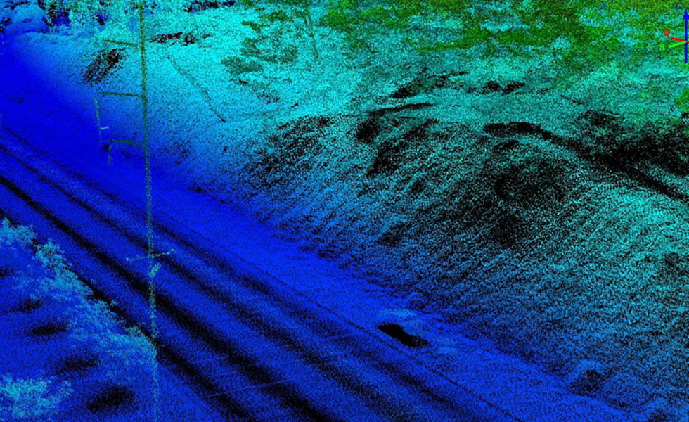
Since the proposed solution is based on unmanned technology, users almost immediately receive accurate information supported by visual details. All this can then be used as evidence in legal proceedings. In addition, the high speed of inspection using aerial scanning helps to quickly begin the process of evacuating wounded or dead people, damaged vehicles, and also quickly begin cleaning the area. In this way, you can clear the roadway for cars in a relatively short time, which is especially important on busy roads, and also save significant money at all stages of work.
Agriculture and landscape planning
Another example of the successful application of new 3D mapping technologies is large farms where it is necessary to create an efficient irrigation system. For example, in large rice plantations, farmers have to create waterproof embankments. This requires precise knowledge of the topography and soil characteristics. Otherwise all created system may turn out to be ineffective and useless. And again optimal solution becomes the Matrice 600 drone with ScanLock technology installed on it. Data collection will occur at a speed of 183 meters per pass. The process of working with one large field will not take much time. At the same time, there is no need, as before, to wait for the cultivated fields to dry out so that the appropriate equipment for data collection can be deployed on them.
Archeology
Where traditional methods of surveying large, historically valuable landscapes required years of work, LiDAR technology can now be used to complete the 3D mapping process in minutes. Once again, the best option for such a procedure would be to install ScanLock on the Matrice 600 drone. “Lost” places and entire ancient cities will be discovered in the shortest possible time.
IN this section we will consider a group of OEPiS with a general technology for obtaining and processing information about remote objects using active optical systems, using the phenomena of light reflection and dispersion in transparent and translucent media.
This group of optical instruments is combined under the name - Lidar(transliteration LIDAR English Light Identification, Detection and Ranging) .
The established translation of LIDAR as “laser radar” is not entirely correct, since the first abbreviation LIDAR appeared in the work of Middleton and Spilhaus “Meteorological Instruments” in 1953, long before the invention of lasers. The first lidars used ordinary or flash lamps with high-speed shutters that generated a short pulse. IN modern systems short-range devices (for example, intended for indoor work) use conventional LEDs instead of lasers. However, it was the use of a laser (due to its properties: coherence, high density and radiation power) that made it possible to create devices with ranges from hundreds of meters to hundreds of kilometers.
The first field tests of the XM-23 wearable laser rangefinder with a radiation power of 2.5 W and a range of measured distances of 200-9995 m took place in 1963. At the same time, in the first half of the 1960s, experiments began on the use of lidar with laser emitters for atmospheric research. In 1969, a laser rangefinder and target mounted on Apollo 11 was used to measure the distance from the Earth to the Moon. Four targets delivered to the Moon by three Apollos and Lunokhod 2 are still used to this day to monitor the orbit of the Moon. During the 1970s, on the one hand, the technology of laser rangefinders and compact semiconductor lasers was fine-tuned, and on the other, research began on the scattering of a laser beam in the atmosphere.
Let's start our consideration of this group of optical devices with the simplest representative - a laser rangefinder. The operating principle is based on the ability of electromagnetic radiation to propagate at a constant speed, which makes it possible to determine the distance to an object. Thus, with the pulse ranging method, the following relationship is used:
where R is the distance to the object, c is the speed of light in a vacuum, n is the refractive index of the medium in which the radiation propagates, t is the time it takes for the pulse to travel to the target and back.
Figure 132 Operating principle of a laser rangefinder.
Consideration of this relationship shows that the potential accuracy of range measurement is determined by the accuracy of measuring the time it takes for the energy pulse to travel to the object and back. It is clear that the shorter the impulse, the better. The task of determining the distance between the rangefinder and the target comes down to measuring the corresponding time interval between the probing signal and the signal reflected from the target. There are three methods for measuring range depending on the type of modulation of laser radiation used in the rangefinder: pulse, phase or pulse phase.
Essence pulse ranging method consists in sending a probing pulse to the object, which also triggers a time counter in the rangefinder. When the impulse reflected by the object reaches the rangefinder, it stops the counter. Based on the time interval (delay of the reflected pulse), the distance to the object is determined.
At phase ranging method laser radiation is modulated according to a sinusoidal law using a modulator (an electro-optical crystal that changes its parameters under the influence of an electrical signal). Typically a sinusoidal signal with a frequency of 10...150 MHz (measuring frequency) is used. The reflected radiation enters the receiving optics and photodetector, where the modulating signal is released. Depending on the distance to the object, the phase of the reflected signal changes relative to the phase of the signal in the modulator. By measuring the phase difference, the distance to the object is determined.
The general block diagram of the simplest lidar is shown in Figure 133 and is similar to a night vision device; in modern military equipment they are even combined.
Figure 133. General block diagram of the simplest lidar (1-laser, 2-object, 3-receiver block, 4-optical system POI (telescopic system), 5-POI, 7-processing and analysis block, 7-information output block, 8 - laser control unit.
Figure 134 shows the modern Russian laser rangefinder "Sazhen-TM-D" used to determine the range to spacecraft equipped with laser retroreflectors, and measure the angular coordinates of the spacecraft using reflected solar radiation to calculate high-precision parameters of the spacecraft's movement, as well as obtain photometric information in the visible wavelength range.
Unlike radio waves, which are effectively reflected only from fairly large metal targets, light waves are subject to scattering in any medium, including air, so it is possible not only to determine the distance to opaque (light reflecting) discrete targets, but also to record the intensity of light scattering in transparent environments.
Figure 134 Rangefinder "Sazhen-TM-D"
It was the measurement of the intensity of laser radiation scattering by atmospheric aerosol that gave the second strong impetus for further development. Lidar sends a short pulse of light into the atmosphere and receives back a backscatter signal. Light scattering in the atmosphere occurs both by air molecules (Rayleigh scattering) and by aerosol particles. Thus, the presence of aerosol in the atmosphere increases the backscatter signal relative to the clear atmosphere, and the aerosol concentration can be determined as a function of distance and signal intensity against the clear atmosphere. Despite the fact that aerosols make up no more than 10% of the total mass of anthropogenic atmospheric pollutants, the potential damage from this type of pollutants, which, as a rule, are strong toxicants, is significantly greater. "Atmospheric" lidars capable of not only determining distances to opaque reflective targets, but also analyzing the properties of a transparent medium that scatters light. A type of atmospheric lidar is Doppler lidars, which determine the direction and speed of movement of air flows in various layers of the atmosphere.
We discussed the physical principles of operation of atmospheric lidars in detail in the section on IR gas analyzers. Here we will focus on design features lidars of this type. As an example, let us consider a modern technique for multi-wavelength laser remote analysis of hazardous atmospheric pollution. The peculiarity is that laser sources can simultaneously generate radiation at several wavelengths in one direction. This allows:
detect and measure the concentrations of several components of hazardous impurities (up to 6) simultaneously in real time;
significantly increase the accuracy of measuring the concentration of hazardous impurities by reducing the influence of temporary fluctuations of the received signal due to atmospheric turbulence.
In a multi-wavelength lidar, pulse-periodic lasers on CO 2 and isotopes of the CO 2 molecule (range 9-11 µm) are used as basic laser systems, and their second (range 4.5-5.5 µm) and third (range 3.0-3.4 µm) can also be used ) harmonics obtained by converting the frequency of radiation from basic lasers in nonlinear crystals such as AgGaSe 2 or ZnGeP 2 with a conversion efficiency of 5-10%. A fundamental difference from the currently used standard schemes of differential laser gas analysis, in which the determined air components are detected one after another, in multi-wavelength laser systems they can be determined almost simultaneously due to the generation of a set of analytical wavelengths simultaneously and their simultaneous detection after passing through the atmospheric volume with increased concentrations of several hazardous gaseous substances.
A diagram of the use of a lidar based on a multi-wavelength ammonia laser for monitoring the atmosphere is shown in Figure 135. A block diagram of a multi-wavelength lidar and its basic optical design are shown in Figures 136 and 137.
Figure 135. Multi-wavelength lidar application diagram
Figure 136. Block – diagram of a multi-wave lidar
Figure 137. Schematic optical diagram of a multi-wavelength lidar
(M – mirrors)
A multi-wave gas analyzer (range up to 10 km), using the latest remote monitoring methods, can be effectively used in a wide variety of areas of production and life: monitoring atmospheric emissions near hazardous chemical production facilities;
control of gas and/or leaks at nuclear fuel cycle enterprises;
identifying pre-emergency situations, monitoring the situation regarding air pollution during emergency situations;
ensuring the security of important facilities - government buildings, military facilities, nuclear power plants, etc.
remote monitoring (for example, from an aircraft or an unmanned satellite) of gas emissions from nuclear industry facilities in third countries in order to identify them, and therefore, determine the ability of these countries to produce nuclear weapons;
determining the dynamics of the spread of toxic clouds in the atmosphere during large-scale accidents;
Figure 138 shows the LSA-2c two-wave lidar and the 4P single-wave lidar intended for sounding atmospheric aerosols and clouds.
They have the same basic characteristic blocks for lidars:
- laser transmitter;
-transmitting optical system;
- receiving optical system;
-spectral analyzing and recording device (PMT, CCD camera, avalanche photodiode);
- signal processing unit;
-Control block;
- system for displaying received information.
Figure 138. Two-wave lidar LSA-2s and single-wave lidar 4P.
As we have already noted, the main emitter in lidars is a laser, which generates short pulses of light of high instantaneous power. The pulse repetition rate or modulating frequency is selected so that the pause between two successive pulses is no less than the response time from detectable targets (which may be physically located further than the estimated range of the device). The choice of wavelength depends on the function of the laser and the security and privacy requirements of the device; The most commonly used Nd:YAG lasers and wavelengths (in nanometers):
§ 1550 nm - infrared radiation, invisible to the human eye and typical night vision devices. The eye is not able to focus these waves on the surface of the retina, so the traumatic threshold for wave 1550 is significantly higher than for shorter waves. However, the risk of eye damage is actually higher than that of visible light emitters - since the eye does not react to infrared radiation, the human natural protective reflex does not work either
§ 1064 nm - near-infrared radiation from neodymium and ytterbium lasers, invisible to the eye, but detectable by night vision devices
§ 532 nm - green radiation from a neodymium laser, effectively “piercing” masses of water
§ 355 nm - near ultraviolet radiation
Problems solved by the use of Lidars:
· Atmospheric research
Atmospheric research with stationary lidars remains the most public area of application of the technology. Several permanent research networks (interstate and university) have been deployed around the world to monitor atmospheric phenomena.
· Measuring the speed and direction of air flows.
Theoretical background The use of ground-based Doppler lidar for such measurements was given back in the 1980s. The principle of operation is based on the use of the Doppler effect, according to which the frequency of the received signal reflected from the target may differ from the frequency of the emitted signal and the difference depends on the ratio of the objects’ velocities relative to each other. In 2001, Alcatel proposed placing lidars on board satellites, so that a “constellation” of satellites in orbit could track the movement of air masses within an entire continent, and potentially the Earth as a whole.
· Atmospheric temperature measurement. Several basic methods for measuring temperature profiles have been developed and implemented in practice.
In the first method Resonant scattering on alkali metal atoms, in particular sodium, potassium, and iron, is used. Clouds of metal atoms are located at an altitude of 85 - 100 km. Temperature is measured by the Doppler broadening of resonance lines using sensing with a narrow-band tunable laser. The first measurements were made using artificial sodium clouds thrown into the atmosphere by rockets. Although the method is limited to the range of heights at which metal atoms are present, the scattered signal is relatively large, and this makes it possible to measure temperature with an accuracy of 1.5 ˚K.
Second method- Rayleigh scattering method (Rayleigh lidar), based on non-resonant scattering of light on air molecules. It was first used in 1953 in experiments with searchlight sounding of the atmosphere. The essence of the method is as follows. If there is no aerosol scattering, then the power of the backscattered signal is directly proportional to the air density, from which the temperature can be calculated. The rarefaction of air with height allows the use of the Rayleigh scattering method at altitudes of no more than 90 km. The lower limit of the measurement altitude (about 20-30 km) is due to the presence in the boundary layer of a large amount of aerosol, which significantly increases scattering, but has virtually no effect on air density.
Third method based on rotational Raman (Raman) scattering by air molecules (Raman lidar). As the temperature increases, the intensity of transitions with large quantum numbers increases, while the intensity of the lines in the rotational Raman spectrum corresponding to small quantum numbers decreases. Transitions with large quantum numbers correspond to lines in the Raman spectrum located further from the center frequency. Temperature is determined using measurements in two spectral regions with different temperature dependences. The maximum sounding altitude is about 30 km, the measurement error is less than 1 ˚K up to a height of 10 km. Since the elastic scattering line is suppressed in the receiver, measurements can be carried out in the presence of significant concentrations of aerosols.
· Early warning of forest fires.
· Earth Research
Instead of installing the lidar on the ground, where the received reflected light would be noisy due to scattering in the polluted lower layers of the atmosphere, an “atmospheric” lidar can be lifted into the air or into orbit, which significantly improves the signal-to-noise ratio and effective range of the system. The first full-fledged orbital lidar was launched into orbit by NASA in December 1994 as part of the LITE (Lidar In-Space Technology Experiment) program. The two-ton LITE lidar with a meter-long mirror telescope, raised to an altitude of 260 km, “painted” a blurry spot with a diameter of 300 m on the ground, which was clearly not enough to effectively display the relief, and was exclusively “atmospheric”.
· Space geodesy.
The relief of the earth's surface is scanned with an acceptable resolution.
· Aviation geodesy.
The US National Oceanographic Service (NOAA) systematically applies There are aviation lidars for topographic surveys of the sea coast.
A special direction used in practice in earthquake-prone areas of the United States is differential measurement of heights in order to identify local movements of earth masses in the area of faults. Back in 1996, a previously unknown fault zone near Seattle was discovered using lidar.
Not long ago, using a similar lidar, a group of scientists from the University of Houston may have managed to find the legendary Golden City in the jungles of Honduras.
Figure 139 Use of previously classified military
laser mapping technology.
· Construction and mining
Construction - measurements of buildings, control of the deviation of the planes of walls and load-bearing columns from the vertical (including dynamics), analysis of vibrations of walls and glazing. Dimensions of pits, creation of three-dimensional models of construction sites to estimate the volume of excavation work.
Architecture- construction of three-dimensional models of the urban environment to assess the impact of proposed new buildings on the appearance of the city.
Marine technology
Measuring the depth of the sea. For this task, an aircraft-based differential lidar is used. Red waves are almost completely reflected by the sea surface, while green waves partially penetrate the water, are scattered in it, and are reflected from the seabed. The technology has not yet been used in civil hydrography due to high measurement errors and a small range of measured depths.
Search for fish. Similar means can detect signs of schools of fish in near-surface water layers. Specialists from the American state laboratory ESRL claim that searching for fish with light aircraft equipped with lidars is at least an order of magnitude cheaper than with ships equipped with echo sounders.
· Industrial and service robots
Near-range machine vision systems for robots, based on IBM scanning lidar, form a cylindrical scan with a horizon coverage angle of 360° and a vertical viewing angle of up to +30..-30
· Military technology
Here, lidars are most widely used and perform the functions of optical-location location, reconnaissance, target guidance, etc.
Figure 139. Attack missile detector (AMD), OLS-35 optical-location station
Figure 140. Means of national technical control of strategic weapons testing in accordance with international Treaties.
4.8 INTERFEROMETERS
Interferometers are measuring instruments whose operation is based on the phenomenon of interference.
The operation of the devices is based on the sequential decomposition of a radiation beam (into two or more coherent beams, each of them passes through different optical paths) and their subsequent addition, as a result, an interference pattern is created, from which the phase shift of the beams can be determined.
Interferometers are used to measure the angular sizes of stars and the angular distances between stars, measure the refractive indices of gases and liquids, and determine the concentration of impurities in the air. Interferometers are used to control the quality of optical parts and their surfaces, to control the cleanliness of the processing of metal surfaces.
Since the principle of operation of interferometers is based on the phenomenon of light interference, we will begin our study of this group of devices by studying this phenomenon.
Light interference is a redistribution of light intensity as a result of the superposition (superposition) of several light waves. This phenomenon is accompanied by alternating maxima and minima of intensity in space. Its distribution is called an interference pattern.
The phenomenon of interference was first independently discovered by Robert Boyle (1627-1691) and Robert Hooke (1635-1703). They observed the appearance of multi-colored thin films (interference fringes), similar to oil or gasoline stains on the surface of water. In 1801, Thomas Young (1773-1829), introducing the “Principle of Superposition,” was the first to explain the phenomenon of interference of light and coined the term “interference” (1803). He also performed the first demonstration experiment to observe the interference of light, obtaining interference from two slit light sources (1802); Jung's experience later became a classic.
Figure 141. Young's experiment and interference in thin film.
Another method of obtaining a stable interference pattern for light is the use of air gaps, based on the same difference in the path of two parts of the wave: one immediately reflected from the inner surface of the lens and the other passing through the air gap under it and only then being reflected. It can be obtained by placing a plano-convex lens on a glass plate with the convex side down. When the lens is illuminated from above with monochromatic light, a dark spot is formed at the point of fairly close contact between the lens and the plate, surrounded by alternating dark and light concentric rings of varying intensities. Dark rings correspond to interference minima, and light ones correspond to maxima; at the same time, dark and light rings are isolines of equal thickness of the air gap. By measuring the radius of a light or dark ring and determining its serial number from the center, you can determine the wavelength of monochromatic light. The steeper the surface of the lens, especially closer to the edges, the smaller the distance between adjacent light or dark rings. This technique is used to control optical parts.
Figure 142. Newton's rings
Having analyzed the phenomenon of interference, let's move on to considering the schemes for constructing interferometers.
Michelson interferometer is one of the most common skeletal interferometer circuits, intended for various applications in cases where spatial alignment of objects generating interfering waves is impossible or for some reason undesirable.
Figure 143. Michelson interferometer
Michelson Stellar Interferometer- an interferometer for measuring the angular sizes of stars and the angular distances between double stars. If the angular distance between two stars is very small, in a telescope they are visible as one star. In this case, they speak of double stars and special observations must be made to distinguish them from single stars. For this purpose, a Michelson stellar interferometer is used, which also allows one to determine the angular distance between stars.
Figure 143. Michelson stellar interferometer
Rays of light coming from a distant star are reflected from flat mirrors M1 - M2, separated by sufficient distance long distance D, are then reflected from two other mirrors and collected by a lens on a screen placed in the focal plane. Mirrors spaced at a distance D can be considered as point sources, the distance between which is equal to D. As a result, an interference pattern is observed in the image of the star, similar to the interference from two slits located at a distance D from each other. The angular distance between adjacent interference maxima in this picture is equal to θ=λ/D, where λ is the wavelength of light. If there are two close stars located at a small angular distance φ from each other, 2 interference patterns are formed in the telescope, which are also shifted by an angle φ and overlap each other. Depending on the ratio of the angles θ and φ, the visibility of the stripes of the total picture will be different. By changing the distance D and, therefore, changing the angle θ, it is possible to achieve a combination of the maxima of one interference pattern with the minima of another, resulting in the worst visibility of the fringes. Under these conditions φ=½θ=λ/2D. By measuring D and knowing λ, we can determine the angular distance between the stars φ. The angular dimensions of one star are determined similarly. If the star is considered as a uniformly luminous disk, then the calculation shows that the disappearance of the stripes occurs at φ=1.22λ/D. The larger the base D, the greater the measurement accuracy of a stellar interferometer. A stellar interferometer has been built in which D can reach 18 m, which makes it possible to measure the angular distance with an accuracy of 0.001". To measure the angular sizes of very faint stars, the light from which is at the noise level, The intensity correlation method is used.
Rozhdestvensky interferometer– this is a two-beam interferometer consisting of 2 mirrors M1, M2 and two parallel translucent plates P1, P2; M1, P1 and M2, P2 are installed in pairs in parallel, but M1 and M2 are inclined relative to each other at a small angle; distance M1P1 = M2P2 and M1P2=P1M2. The light beam is divided by plate P1 into 2 beams, which, after reflections from M1, M2 and passage of P2, turn out to be parallel with a phase difference
δ = (4πD/λ)(cos i1 - cos i2).
Figure 144. Rozhdestvensky interferometer
Since δ does not depend on the position of the rays on the mirrors and is determined only by the angles of incidence, the interference pattern will be localized at infinity (or in the focal plane of the lens O). A parallel beam of rays incident on the Rozhdestvensky Interferometer corresponds to one point in the interference pattern, and, therefore, to observe the entire pattern, a beam of finite aperture is required. The appearance of the pattern (the order and width of the stripes, their orientation) depends on the inclination of the mirrors M1 and M2. If, for example, the edge of the dihedral angle formed by M1 and M2 is vertical (perpendicular to the drawing), then even with a very small difference (i1-i2) the stripes of a relatively high order (D is large) are vertical and almost parallel. If the edge of the dihedral angle is horizontal, then in the field of view are horizontal stripes low order (including zero), visible in white light. Introduction into one of the bundles of k.-l. of a transparent object, such as a plate, changes the width, order and orientation of the stripes: the zero stripe is not horizontal and appears at some intermediate orientation of M1 and M2; with the very large thickness of this plate, only very narrow, almost vertical stripes can be seen in white light, when the edge of the angle between M1 and M2 is almost vertical. The width of the stripes depends on the angle between M1 and P1, increasing as it decreases. If all mirrors and plates are parallel, then in the absence of inhomogeneities the width of the stripes is infinite (the interference field is uniformly illuminated).
Jamin Interferometer(interference refractometer) - an interferometer for measuring the refractive indices of gases and liquids, as well as for determining the concentration of impurities in the air.
The Jamin interferometer consists of two identical thick plane-parallel glass (or quartz) plates installed almost parallel to each other. A beam of light falls on the first plate at an angle i close to 45°. Each ray of the beam, after reflection on the surfaces of the plate, is divided into 2 coherent rays S1 and S2, traveling at a certain distance from each other, depending on the thickness of the plates d. Then, on the second plate, each of them is similarly divided into two beams. As a result, 4 parallel coherent rays S1’, S1”, S2’, S2” come from the second plate; The middle beams S1” and S2’ are superimposed and form an interference pattern in the focal plane of the lens O1.
Figure 145. Diagram of the Jamin interferometer: OO – axis of rotation of the compensating plates; L – compensator rotation dial; O1 and O2 – lens and eyepiece of the telescope.
The difference between them is equal to
where n n is the refractive index of the plates.
φ - angle between them.
At (φ ≈ 5′ - 15′ ∆ is small, therefore, when using a white light source, only low-order interference fringes are observed, which have the form of straight lines with a white achromatic stripe in the center, surrounded by a system of colored stripes.).
The relatively large distance between the beams S1 and S2 makes it possible to install on their path two cuvettes K1 and K2 of the same length l with the substances under study, the refractive indices of which are n1 and n2. The resulting path difference will cause a shift in the interference pattern.
∆ = (n2-n1)l = δnl
Using the Jamin Interferometer, a quantitative analysis of gas mixtures is carried out - the concentration of certain gaseous impurities, such as methane and CO2, in the air of mines is determined (since n depends on the nature of the gas).
Interferometer Physo- one of the simplest interferometers used mainly to control the accuracy of manufacturing flat optical surfaces. details.
Light from a monochromatic source L, using condenser O1, diaphragm D and objective O2, is directed in a parallel beam onto the reference E and controlled K plates (placed one on top of the other) almost perpendicular to their surfaces. In this case, the strictly flat reference and controlled surfaces of the plates form a small angle a between themselves. Using a translucent plate P, interference fringes of equal thickness are observed in reflected light, which are localized in the region of the air wedge between the controlled and reference surfaces.
Figure 146. Fizeau interferometer; a - View of defects from above on the controlled plate; b - Cross section of the reference and control plates. Section along the line AA (angle a and the size of the defects are greatly enlarged for clarity); c - View of the interference pattern of stripes of equal thickness in the Fizeau interferometer.
The positions of these stripes are determined from the condition: D=2dn+l/2=ml=const (at n~1), where d is the thickness of the air wedge. If the controlled surface is ideally flat, then the strips of equal inclination have the form of straight equidistant lines parallel to the edge of the wedge (d=const), the distance between them is z=l/2a (Fig. 2, c) (at a=10 "" and l~0.5 µm, z=5 mm). If there are some on the controlled surface. defects, for example, small depressions or protrusions, as in the figure, or it is not strictly flat, then deviations dz from straightness are observed in the area where these defects are located. In this case, the magnitude of the deviation dz/z is related to the height or depth of the defect dh by the ratio dh=(l/2)dz/z.
The naked eye can estimate the value dz/z~0.l, which corresponds to the value of the detected defect dh=l/20 (at l=0.633 μm, dh=0.031 μm). The deviation sign allows you to distinguish the type of defect: a depression or a protrusion. If the controlled surface has the shape of a sphere, then the interference fringes have the shape of concentric circles (see Newton's rings). In a Fizeau interferometer, the surfaces of the controlled and reference plates, due to the smallness of the angle (arc.seconds), are almost completely in contact with each other and can be damaged during the adjustment process. Therefore, non-contact interferometers built according to the Michelson interferometer scheme are often used to control surfaces.
Figure 147. Fizeau interferometer designed by Romanov is designed for non-contact measurement of the shape of flat polished surfaces and mirrors. Software designed for processing interference patterns with additionally introduced tilts.
Literature.
- D. N. Cherkasova, A. V. Bakholdin / “Optical ophthalmological devices and systems Part I” / St. Petersburg 2010.
- Lukin S.B. / “LECTURE NOTES ON THE ECO COURSE” / St. Petersburg State University ITMO 2004.
- Latyev S.M./ “Design of precision (optical) instruments”/ Electronic textbook on the discipline: “Fundamentals of the design of optical instruments.” SPbSU ITMO
- A.L. Andreev / “Automated television surveillance systems” / St. Petersburg State University ITMO
- Mitrofanov S.S / “Theoretical and physical foundations of the OP device” / Electronic textbook on the discipline: “Applied optics”. St. Petersburg State University ITMO, department of KPOP
- http://biggest.su/samyj-bolshoj-teleskop/
7. V. Samokhin, N. Terekhova / “Video projection today and tomorrow”
8. M.A. Kustikova, M.N. Meshalkina, V.L. Musyakov, A.N. Timofeev/ “Methodological instructions for laboratory work in the section “OPTICAL-ELECTRONIC GAS ANALYZERS” of the course “ECOLOGICAL MONITORING”
10. http://www.krugosvet.ru/enc/nauka_i_tehnika/fizika/OPTIKA.html?page=4.6
11. Zakharyevsky A.N. "Interferometers" 1952.
12. M.M. Miroshnikov / “Theoretical foundations of OEP” / “Mechanical engineering” 1977.
13. M.M. Rusinov / “Dimensional calculations of optical systems” Moscow 1963
14. G.G. Ishanin, M. G. Kozlov, K.A. Tomsk / “Fundamentals of lighting engineering” / St. Petersburg 2004


