The advantages of this transformer have already been appreciated by many of those who have ever dealt with the problems of powering various electronic structures. And this electronic transformer has many advantages. Light weight and dimensions (as with all similar circuits), ease of modification to suit your own needs, the presence of a shielding aluminum body, low cost and relative reliability (at least, if extreme modes and short circuits are avoided, a product made according to a similar circuit is capable of work for many years). The range of application of power supplies based on Taschibra can be very wide, comparable to the use of conventional transformers.
The use is justified in cases of shortage of time, money, and the need for small dimensions.
Well, shall we experiment?
The purpose of the experiments is to test the Tasсhibra trigger circuit under various loads and frequencies. Also checking the temperature conditions of the circuit components when operating under various loads, taking into account the use of the "Tashibra" case as a radiator.
A large number of electronic transformer circuits have been published on the Internet.
Fig1 illustrates the "Taschibra" filling.
The diagram is valid for ET "Taschibra" 60-150W.
What is “Taschibra” missing for a full-fledged power supply?
1. Lack of an input smoothing filter (also an anti-interference filter, which prevents conversion products from entering the network),
2. Current PIC, which allows excitation of the converter and its normal operation only in the presence of a certain load current,
3. No output rectifier,
4. Lack of output filter elements.
Let's try to correct all the listed shortcomings of "Taskhibra" and try to achieve its acceptable operation with the desired output characteristics. To begin with, we won’t even open the housing of the electronic transformer, but simply add the missing elements...
1. Input filter: capacitors C`1, C`2 with a symmetrical two-winding choke (transformer) T`1
2. diode bridge VDS`1 with smoothing capacitor C`3 and resistor R`1 to protect the bridge from the charging current of the capacitor.
The smoothing capacitor is usually selected at the rate of 1.0 - 1.5 μF per watt of power, and a discharge resistor with a resistance of 300-500 kOhm should be connected in parallel to the capacitor for safety (touching the terminals of a capacitor charged with a relatively high voltage is not very pleasant).
Resistor R`1 can be replaced with a 5-15Ohm/1-5A thermistor. Such a replacement will reduce the efficiency of the transformer to a lesser extent.
At the output of the ET, as shown in the diagram in Fig. 3, we connect a circuit of diode VD`1, capacitors C`4-C`5 and inductor L1 connected between them to obtain a filtered DC voltage at the “patient” output. In this case, the polystyrene capacitor placed directly behind the diode accounts for the main share of absorption of conversion products after rectification. It is assumed that electrolytic capacitor, “hidden” behind the inductance of the inductor, will perform only its direct functions, preventing voltage “failure” at the peak power of the device connected to the ET. But it is also recommended to install a non-electrolytic capacitor in parallel with it.
After adding the input circuit, changes occurred in the operation of the electronic transformer: the amplitude of the output pulses (up to the diode VD`1) increased slightly due to an increase in the voltage at the input of the device due to the addition of C 3 and modulation with a frequency of 50 Hz was practically absent. This is at the load calculated for the electric vehicle.
However, this is not enough. Taschibra does not want to start without significant load current.
We are remaking the transformer.
We open the case and make minor changes to the circuit, as in Fig. 2.

pic 2
To run Taschibra stably without load, voltage feedback must be introduced into the circuit.
To do this, you need to take a thin (0.08...0.12mm2.) insulated wire with a length of 200...300mm. In the basic (small) transformer, use an awl to compact the turns (to make room for a new winding. Wind 3 turns onto the transformer (small toroid). Insert one of the ends of the wire into the core of the power transformer and make a half-turn. Do not twist the wires! Connect the ends of the wires through resistor 4, 7...5.6 Ohm 0.5...1W. The wires between the transformers should form 0. If 8 (overlap) is formed, then excitation will not occur. Connect Taschibra without load to the network and make sure that the start is stable, connect the load.
From resistance in the circuit feedback depends on the conversion frequency. The optimal frequency is about 30 kHz. Under load the frequency changes slightly. If you accurately select the resistor value, you can obtain maximum inverter efficiency.

To power the LEDs at the output of the modified electronic transformer, you need to add a rectifier using ultra-fast diodes and a smoothing filter, and the LEDs must be provided with a current stabilizer.
The device has a fairly simple circuit. A simple push-pull self-oscillator, which is made using a half-bridge circuit, the operating frequency is about 30 kHz, but this indicator strongly depends on the output load.
The circuit of such a power supply is very unstable, it does not have any protection against short circuits at the output of the transformer, perhaps precisely because of this, the circuit has not yet found widespread use in amateur radio circles. Although recently there has been a promotion of this topic on various forums. People offer various options for modifying such transformers. Today I will try to combine all these improvements in one article and offer options not only for improvements, but also for strengthening the ET.
We won’t go into the basics of how the circuit works, but let’s get down to business right away.
We will try to refine and increase the power of the Chinese Taschibra electric vehicle by 105 watts.
To begin with, I want to explain why I decided to take on the powering and alteration of such transformers. The fact is that recently a neighbor asked me to make him a custom-made charger for a car battery that would be compact and lightweight. I didn’t want to assemble it, but later I came across interesting articles that discussed remaking an electronic transformer. This gave me the idea - why not try it?
Thus, several ETs from 50 to 150 Watts were purchased, but experiments with conversion were not always completed successfully; of all, only the 105 Watt ET survived. The disadvantage of such a block is that its transformer is not ring-shaped, and therefore it is inconvenient to unwind or rewind the turns. But there was no other choice and this particular block had to be remade.
As we know, these units do not turn on without load; this is not always an advantage. I plan to get a reliable device that can be freely used for any purpose without fear that the power supply may burn out or fail during a short circuit.
Improvement No. 1
The essence of the idea is to add short-circuit protection and also eliminate the above-mentioned drawback (activation of a circuit without an output load or with a low-power load).

Looking at the unit itself, we can see the simplest UPS circuit; I would say that the circuit has not been fully developed by the manufacturer. As we know, if you short-circuit the secondary winding of a transformer, the circuit will fail in less than a second. The current in the circuit increases sharply, the switches instantly fail, and sometimes even the basic limiters. Thus, repairing the circuit will cost more than the cost (the price of such an ET is about $2.5).

The feedback transformer consists of three separate windings. Two of these windings power the base switch circuits.
First, remove the communication winding on the OS transformer and install a jumper. This winding is connected in series with the primary winding of the pulse transformer.
Then we wind only 2 turns on the power transformer and one turn on the ring (OS transformer). For winding, you can use a wire with a diameter of 0.4-0.8 mm.


Next, you need to select a resistor for the OS, in my case it is 6.2 ohms, but a resistor can be selected with a resistance of 3-12 ohms, the higher the resistance of this resistor, the lower the short-circuit protection current. In my case, the resistor is a wirewound one, which I do not recommend doing. We select the power of this resistor to be 3-5 watts (you can use from 1 to 10 watts).

During a short circuit on the output winding of a pulse transformer, the current in the secondary winding drops (in standard ET circuits, during a short circuit, the current increases, disabling the switches). This leads to a decrease in the current on the OS winding. Thus, generation stops and the keys themselves are locked.
The only drawback of this solution is that in the event of a long-term short circuit at the output, the circuit fails because the switches heat up quite strongly. Do not expose the output winding to a short circuit lasting more than 5-8 seconds.
The circuit will now start without load; in a word, we have a full-fledged UPS with short-circuit protection.

Improvement No. 2
Now we will try to smooth out the mains voltage from the rectifier to some extent. For this we will use chokes and a smoothing capacitor. In my case, a ready-made inductor with two independent windings was used. This inductor was removed from the UPS of the DVD player, although homemade inductors can also be used.

After the bridge, an electrolyte with a capacity of 200 μF should be connected with a voltage of at least 400 Volts. The capacitor capacity is selected based on the power of the power supply 1 μF per 1 watt of power. But as you remember, our power supply is designed for 105 Watts, why is the capacitor used at 200 μF? You will understand this very soon.
Improvement No. 3
Now about the main thing - increasing the power of the electronic transformer and is it real? In fact, there is only one reliable way to power it up without much modification.
For powering up, it is convenient to use an ET with a ring transformer, since it will be necessary to rewind the secondary winding; it is for this reason that we will replace our transformer.
The network winding is stretched across the entire ring and contains 90 turns of wire 0.5-0.65 mm. The winding is wound on two folded ferrite rings, which were removed from an ET with a power of 150 watts. The secondary winding is wound based on needs, in our case it is designed for 12 Volts.
It is planned to increase the power to 200 watts. That is why an electrolyte with a reserve, which was mentioned above, was needed.
We replace the half-bridge capacitors with 0.5 μF; in the standard circuit they have a capacity of 0.22 μF. Bipolar keys MJE13007 are replaced with MJE13009.
The power winding of the transformer contains 8 turns, the winding was done with 5 strands of 0.7 mm wire, so we have a wire in the primary with a total cross-section of 3.5 mm.
Go ahead. Before and after the chokes we place film capacitors with a capacity of 0.22-0.47 μF with a voltage of at least 400 Volts (I used exactly those capacitors that were on the ET board and which had to be replaced to increase the power).

Next, replace the diode rectifier. In standard circuits, conventional rectifier diodes of the 1N4007 series are used. The current of the diodes is 1 Ampere, our circuit consumes a lot of current, so the diodes should be replaced with more powerful ones in order to avoid unpleasant results after the first turn on of the circuit. You can use literally any rectifier diodes with a current of 1.5-2 Amps, a reverse voltage of at least 400 Volts.
All components except the generator board are mounted on a breadboard. The keys were secured to the heat sink through insulating gaskets.
We continue our modification of the electronic transformer, adding a rectifier and filter to the circuit.
The chokes are wound on rings made of powdered iron (removed from a computer power supply unit) and consist of 5-8 turns. It is convenient to wind it using 5 strands of wire with a diameter of 0.4-0.6 mm each.
Today, electromechanics rarely repair electronic transformers. In most cases, I myself don’t really bother with working on resuscitating such devices, simply because, usually, buying a new electronic transformer is much cheaper than repairing an old one. However, in the opposite situation, why not work hard to save money. In addition, not everyone has the opportunity to get to a specialized store to find a replacement there, or go to a workshop. For this reason, any radio amateur needs to be able to and know how to check and repair pulse (electronic) transformers at home, what ambiguous issues may arise and how to resolve them.
Due to the fact that not everyone has an extensive amount of knowledge on the topic, I will try to present all available information as accessible as possible.
A little about transformers
Fig.1: Transformer.
Before proceeding to the main part, I will give a short reminder about what an electronic transformer is and what it is intended for. A transformer is used to convert one variable voltage to another (for example, 220 volts to 12 volts). This property of an electronic transformer is very widely used in radio electronics. There are single-phase (current flows through two wires - phase and “0”) and three-phase (current flows through four wires - three phases and “0”) transformers. The main significant point when using an electronic transformer is that as the voltage decreases, the current in the transformer increases.
A transformer has at least one primary and one secondary winding. The supply voltage is connected to the primary winding, a load is connected to the secondary winding, or the output voltage is removed. In step-down transformers, the primary winding wire always has a smaller cross-section than the secondary wire. This allows you to increase the number of turns of the primary winding and, as a result, its resistance. That is, when checked with a multimeter, the primary winding shows a resistance many times greater than the secondary. If for some reason the diameter of the secondary winding wire is small, then, according to the Joule-Lance law, the secondary winding will overheat and burn the entire transformer. A transformer malfunction may consist of a break or short circuit (short circuit) of the windings. If there is a break, the multimeter shows one on the resistance.
How to test electronic transformers?
In fact, to figure out the cause of the breakdown, you don’t need to have a huge amount of knowledge; it’s enough to have a multimeter on hand (standard Chinese, as in Figure 2) and know what numbers each component (capacitor, diode, etc.) should produce at the output. d.).

Figure 2: Multimeter.
The multimeter can measure DC, AC voltage and resistance. It can also work in dialing mode. It is advisable that the multimeter probe be wrapped with tape (as in Figure No. 2), this will protect it from breaks.
In order to correctly test the various elements of the transformer, I recommend desoldering them (many try to do without this) and examining them separately, since otherwise the readings may be inaccurate.
Diodes
We must not forget that diodes only ring in one direction. To do this, set the multimeter to continuity mode, the red probe is applied to the plus, the black probe to the minus. If everything is normal, the device makes a characteristic sound. When the probes are applied to opposite poles, nothing should happen at all, and if this is not the case, then a breakdown of the diode can be diagnosed.
Transistors
When checking transistors, they also need to be unsoldered and the base-emitter, base-collector junctions must be wired, identifying their permeability in one direction and the other. Typically, the role of a collector in a transistor is performed by the rear iron part.
Winding
We must not forget to check the winding, both primary and secondary. If you have problems determining where the primary winding is and where the secondary winding is, then remember that the primary winding gives more resistance.
Capacitors (radiators)
The capacitance of a capacitor is measured in farads (picofarads, microfarads). To study it, a multimeter is also used, on which the resistance is set to 2000 kOhm. The positive probe is applied to the minus of the capacitor, the negative to the plus. Increasing numbers should appear on the screen up to almost two thousand, which are replaced by one, which stands for infinite resistance. This may indicate the health of the capacitor, but only in relation to its ability to accumulate charge.
One more point: if during the dialing process there is confusion about where the “input” is located and where the “output” of the transformer is located, then you just need to turn the board over and on the back side at one end of the board you will see a small marking “SEC” (second), which indicates the output, and on the other “PRI” (first) the input.
And also, do not forget that electronic transformers cannot be started without loading! It is very important.
Electronic transformer repair
Example 1
The opportunity to practice repairing a transformer presented itself not so long ago, when they brought me an electronic transformer from a ceiling chandelier (voltage - 12 volts). The chandelier is designed for 9 bulbs, each 20 watts (180 watts in total). On the packaging of the transformer it also said: 180 watts. But the mark on the board said: 160 watts. The country of origin is, of course, China. A similar electronic transformer costs no more than $3, and this is actually quite a bit when compared with the cost of the other components of the device in which it was used.
In the electronic transformer I received, a pair of keys burned out bipolar transistors(Model: 13009).

The operating circuit is a standard push-pull, in place of the output transistor there is a TOP inverter, whose secondary winding consists of 6 turns, and alternating current is immediately redirected to the output, that is, to the lamps.
Such power supplies have a very significant drawback: there is no protection against short circuit at the output. Even with a short-circuit of the output winding, you can expect a very impressive explosion of the circuit. Therefore, it is highly not recommended to take risks in this way and short-circuit the secondary winding. In general, it is for this reason that radio amateurs do not really like to mess with electronic transformers of this type. However, some people, on the contrary, try to modify them on their own, which, in my opinion, is quite good.
But let's get back to the point: since there was a darkening of the board right under the keys, there was no doubt that they failed precisely because of overheating. Moreover, the radiators do not actively cool the case box filled with many parts, and they are also covered with cardboard. Although, judging by the initial data, there was also an overload of 20 watts.
Due to the fact that the load exceeds the capabilities of the power supply, reaching the rated power is almost equivalent to failure. Moreover, ideally, with a view to long-term operation, the power of the power supply should be not less, but twice as much as necessary. This is what Chinese electronics is like. It was not possible to reduce the load level by removing several light bulbs. Therefore, the only suitable option, in my opinion, to correct the situation was to increase the heat sinks.
To confirm (or refute) my version, I launched the board directly on the table and applied the load using two halogen pair lamps. When everything was connected, I dripped a little paraffin onto the radiators. The calculation was as follows: if the paraffin melts and evaporates, then we can guarantee that the electronic transformer (fortunately, if only it is itself) will burn out in less than half an hour of operation due to overheating. After 5 minutes of operation, the wax did not melt, it turned out that the main problem is related precisely to poor ventilation, and not to a malfunction of the radiator. The most elegant solution to the problem is to simply fit another larger housing under the electronic transformer, which will provide sufficient ventilation. But I preferred to connect a heat sink in the form of an aluminum strip. Actually, this turned out to be quite enough to correct the situation.
Example 2
As another example of repairing an electronic transformer, I would like to talk about repairing a device that reduces the voltage from 220 to 12 Volts. It was used for 12 Volt halogen lamps (power - 50 Watt).

The copy in question stopped working without any special effects. Before I got it into my hands, several craftsmen refused to work with it: some could not find a solution to the problem, others, as mentioned above, decided that it was not economically feasible.
To clear my conscience, I checked all the elements and traces on the board and found no breaks anywhere.
Then I decided to check the capacitors. The diagnostics with a multimeter seemed to be successful, however, taking into account the fact that the charge accumulated for as long as 10 seconds (this is a lot for capacitors of this type), a suspicion arose that the problem was in it. I replaced the capacitor with a new one.
A small digression is needed here: on the body of the electronic transformer in question there was a designation: 35-105 VA. These readings indicate at what load the device can be turned on. It is impossible to turn it on without a load at all (or, in human terms, without a lamp), as mentioned earlier. Therefore, I connected a 50-watt lamp to the electronic transformer (that is, a value that fits between the lower and upper limits of the permissible load).

Rice. 4: 50W halogen lamp (package).
After connection, no changes occurred in the performance of the transformer. Then I completely examined the design again and realized that during the first check I did not pay attention to the thermal fuse (in this case, model L33, limited to 130C). If in the continuity mode this element gives one, then we can talk about its malfunction and an open circuit. Initially, the thermal fuse was not tested for the reason that it is attached tightly to the transistor using heat shrink. That is, to fully check the element, you will have to get rid of the heat shrinkage, and this is very labor-intensive.

Fig. 5: Thermal fuse attached by heat shrink to the transistor (the white element pointed to by the handle).
However, to analyze the operation of the circuit without of this element, just short-circuit its “legs” on the reverse side. Which is what I did. The electronic transformer immediately started working, and the earlier replacement of the capacitor turned out to be not superfluous, since the capacity of the previously installed element did not meet the declared one. The reason was probably that it was simply worn out.
As a result, I replaced the thermal fuse, and at this point the repair of the electronic transformer could be considered complete.
Write comments, additions to the article, maybe I missed something. Take a look at, I will be glad if you find something else useful on mine.
Electronic transformers for halogen lamps (HT)- a topic that is not losing relevance among both experienced and very mediocre radio amateurs. And this is not surprising, because they are very simple, reliable, compact, easy to modify and improve, which significantly expands their scope of application. And due to the massive transition of lighting technology to LED technology, ETs have become obsolete and have fallen greatly in price, which, in my opinion, has become almost their main advantage in amateur radio practice.
There is a lot of different information about ET regarding the advantages and disadvantages, design, principle of operation, modification, modernization, etc. But finding the right circuit, especially high-quality devices, or purchasing a unit with the required configuration can be very problematic. Therefore, in this article I decided to present photos, sketched diagrams with winding data and short reviews those devices that came (will fall) into my hands, and in the next article I plan to describe several options for alterations of specific ETs from this topic.
For clarity, I conditionally divide all ET into three groups:
- Cheap ET or "typical China". As a rule, only a basic circuit of the cheapest elements. They often get very hot, have low efficiency, and with a slight overload or short circuit they burn out. Sometimes you come across “factory China”, characterized by higher quality parts, but still far from perfect. The most common type of ET on the market and in everyday life.
- Good ET. The main difference from cheap ones is the presence of overload protection (SC). They reliably hold the load until the protection is triggered (usually up to 120-150%). The equipment is supplied with additional elements: filters, protections, radiators in any order.
- High-quality ET, meeting high European requirements. Well thought out, equipped to the maximum: good heat dissipation, all types of protection, soft start of halogen lamps, input and internal filters, damper and sometimes snubber circuits.
Now let's move on to the ETs themselves. For convenience, they are sorted by power output in ascending order.
1. ET with power up to 60 W.
1.1. L&B

1.2. Tashibra


The two ETs mentioned above are typical representatives of the cheapest China. The scheme, as you can see, is typical and widespread on the Internet.
1.3. Horoz HL370


Factory China. Holds the rated load well and doesn't get too hot.
1.4. Relco Minifox 60 PFS-RN1362


But here is a representative of a good ET made in Italy, equipped with a modest input filter and protection against overload, overvoltage and overheating. Power transistors are selected with a power reserve, so they do not require radiators.
2. ET with a power of 105 W.
2.1. Horoz HL371


Similar to the above model Horoz HL370 (item 1.3.) factory made in China.
2.2. Feron TRA110-105W


There are two versions in the photo: on the left is the older one (2010 onwards) – factory made in China, on the right is the newer one (2013 onwards), reduced in price to typical China.
2.3. Feron ET105


Similar Feron TRA110-105W (item 2.2.) factory China. The photo of the original board was not preserved, so instead I am posting a photo of the Feron ET150, the board of which is very similar in appearance and similar in element base.
2.4. Brilux BZE-105


Similar Relco Minifox 60 PFS-RN1362 (item 1.4.) is a good ET.
3. ET with a power of 150 W.
3.1. Buko BK452


An electric vehicle reduced in price to a factory price in China, into which an overload protection module (SC) was not soldered. And so, the block is quite good in form and content.
3.2. Horoz HL375 (HL376, HL377)


And here is a representative of high-quality ETs with a very rich set of equipment. What immediately catches your eye is the chic two-stage input filter, powerful paired power switches with a volumetric radiator, protection against overload (short circuit), overheating and double overvoltage protection. This model It is also significant in that it is the flagship for the subsequent ones: HL376 (200W) and HL377 (250W). The differences are marked in red on the diagram.
3.3. Vossloh Schwabe EST 150/12.645


Very high quality ET from the world famous German manufacturer. Compact, well-designed, powerful unit with element base from the best European companies.
3.4. Vossloh Schwabe EST 150/12.622


No less quality, more a new version the previous model (EST 150/12.645), characterized by greater compactness and some circuit solutions.
3.5. Brilux BZ-150B (Kengo Lighting SET150CS)


One of the highest quality ETs I've come across. A very well thought out block with a very rich element base. It differs from a similar model Kengo Lighting SET150CS only in the communication transformer, which is slightly smaller in size (10x6x4mm) with the number of turns 8+8+1. The uniqueness of these ETs is their two-stage overload protection (SC), the first of which is self-healing, configured for a smooth start of halogen lamps and light overload (up to 30-50%), and the second is blocking, triggered when an overload exceeds 60% and requires a unit reboot (short-term shutdown followed by switching on). Also noteworthy is the rather large power transformer, the overall power of which allows you to squeeze out up to 400-500 W.
I personally didn’t come across them, but I saw similar models in the photo in the same case and with the same set of elements for 210W and 250W.
4. ET with a power of 200-210 W.
4.1. Feron TRA110-200W (250W)


Similar Feron TRA110-105W (item 2.2.) factory China. Probably the best unit in its class, designed with a large power reserve, and therefore is the flagship model for the absolutely identical Feron TRA110-250W, made in the same housing.
4.2. Delux ELTR-210W


A maximally cheap, slightly clumsy ET with many unsoldered parts and heat dissipation of power switches to a common radiator through pieces of electrical cardboard, which can be classified as good only because of the presence of overload protection.
4.3. Light kit EK210


According to the electronic filling, similar to the previous Delux ELTR-210W (clause 4.2.), a good ET with power switches in a TO-247 housing and two-stage overload protection (SC), despite which it ended up burnt out, almost completely, along with the protection modules ( why are there no photos? After complete recovery, when connecting a load close to the maximum, it burned out again. Therefore, I can’t say anything sensible about this ET. Possibly a marriage, or perhaps poorly thought out.
4.4. Kanlux SET210-N


Without further ado, a pretty high-quality, well-designed and very compact ET.
ET with a power of 200W can also be found in paragraph 3.2.
5. ET with a power of 250 W or more.
5.1. Lemanso TRA25 250W

Typical China. The same well-known Tashibra or a pitiful semblance of Feron TRA110-200W (section 4.1.). Even despite the powerful paired keys, it hardly maintains the declared characteristics. The board was received crippled, without a case, so there is no photo of it.
5.2. Asia Elex GD-9928 250W


Essentially the TRA110-200W model improved to a good ET (clause 4.1.). Up to half of the housing is filled with a thermally conductive compound, which significantly complicates its disassembly. If you come across one and need to disassemble it, put it in the freezer for several hours, and then quickly break off the frozen compound piece by piece until it warms up and becomes viscous again.
The next most powerful model, Asia Elex GD-9928 300W, has an identical body and circuit.
ET with a power of 250W can also be found in paragraph 3.2. and clause 4.1.
Well, that’s probably all ET for today. In conclusion, I will describe some nuances, features and give a couple of tips.
Many manufacturers, especially cheap ETs, produce this product under different names (brands, types) using the same circuit (case). Therefore, when searching for a circuit, you should pay more attention to its similarity than to the name (type) of the device.
It is almost impossible to determine the quality of an ET based on the body, since, as can be seen in some photos, the model may be understaffed (with missing parts).
Good and quality models As a rule, they are made of high-quality plastic and can be disassembled quite easily. Cheap ones are often held together with rivets, and sometimes glued together.
If after disassembly it is difficult to determine the quality of the electric vehicle, pay attention to printed circuit board– cheap ones are usually mounted on getinax, high-quality ones are mounted on textolite, good ones, as a rule, are also mounted on textolite, but there are rare exceptions. The quantity (volume, density) of radio components will tell you a lot. Inductive filters are always absent in cheap ETs.
Also, in cheap ETs, the heat sink of power transistors is either completely absent, or is placed on the housing (metal) through electrical cardboard or PVC film. In high-quality and many good ETs, it is made on a volumetric radiator, which usually fits tightly to the body from the inside, also using it to dissipate heat.
The presence of overload protection (SC) can be determined by the presence of at least one additional low-power transistor and low-voltage electrolytic capacitor on the board.
If you plan to purchase an ET, then note that there are many flagship models that are cheaper in price than their “more powerful” copies. Electronic transformers.
Success in life and creative work to all.
Let's consider the main advantages, advantages and disadvantages of electronic transformers. Let's consider the scheme of their work. Electronic transformers appeared on the market quite recently, but managed to gain wide popularity not only in amateur radio circles.
Recently, articles based on electronic transformers have often been seen on the Internet: homemade power supplies, charging device and much more. In fact, electronic transformers are simple network transformers. This is the cheapest power supply. It's more expensive for a phone. The electronic transformer operates from a 220 volt network.
Device and principle of operation
Scheme of work
The generator in this circuit is a diode thyristor or dinistor. The 220 V mains voltage is rectified by a diode rectifier. There is a limiting resistor at the power input. It simultaneously serves as a fuse and protection against surges in mains voltage when turned on. The operating frequency of the dinistor can be determined from the ratings of the R-C chain.
In this way, the operating frequency of the generator of the entire circuit can be increased or decreased. The operating frequency in electronic transformers is from 15 to 35 kHz, it can be adjusted.

The feedback transformer is wound on a small core ring. It contains three windings. The feedback winding consists of one turn. Two independent windings of master circuits. These are the basic windings of transistors of three turns.
These are equal windings. Limiting resistors are designed to prevent false triggering of transistors and at the same time limit the current. Transistors are used of high-voltage type, bipolar. MGE 13001-13009 transistors are often used. It depends on the power of the electronic transformer.
A lot also depends on the half-bridge capacitors, in particular the power of the transformer. They are used with a voltage of 400 V. From overall dimensions The core of the main pulse transformer also depends on the power. It has two independent windings: mains and secondary. Secondary winding with a rated voltage of 12 volts. It is wound based on the required output power.
The primary or network winding consists of 85 turns of wire with a diameter of 0.5-0.6 mm. Low-power rectifier diodes with a reverse voltage of 1 kV and a current of 1 ampere are used. This is the cheapest rectifier diode you can find in the 1N4007 series.
The diagram shows in detail the capacitor that sets the frequency of the dinistor circuits. A resistor at the input protects against voltage surges. Dinistor series DB3, its domestic analogue KN102. There is also a limiting resistor at the input. When the voltage on the frequency-setting capacitor reaches the maximum level, breakdown of the dinistor occurs. A dinistor is a semiconductor spark gap that operates at a certain breakdown voltage. Then it sends a pulse to the base of one of the transistors. The generation of the circuit begins.
Transistors operate in antiphase. An alternating voltage is generated on the primary winding of the transformer at a given dinistor operating frequency. On the secondary winding we get the required voltage. In this case, all transformers are designed for 12 volts.
Electronic transformers from Chinese manufacturer
It is designed to power 12 volt halogen lamps.

With a stable load, such as halogen lamps, such electronic transformers can operate indefinitely. During operation, the circuit overheats, but does not fail.
Operating principle
A voltage of 220 volts is supplied and rectified by the VDS1 diode bridge. Through resistors R2 and R3, capacitor C3 begins to charge. The charge continues until the DB3 dinistor breaks through.
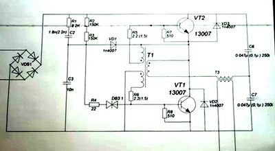
The opening voltage of this dinistor is 32 volts. After it opens, voltage is supplied to the base of the lower transistor. The transistor opens, causing self-oscillation of these two transistors VT1 and VT2. How do these self-oscillations work?
Current begins to flow through C6, transformer T3, base control transformer JDT, transistor VT1. When passing through the JDT it causes VT1 to close and VT2 to open. After this, the current flows through VT2, through the base transformer, T3, C7. Transistors constantly open and close each other, working in antiphase. At the midpoint, rectangular pulses appear.
The conversion frequency depends on the inductance of the feedback winding, the capacitance of the transistor bases, the inductance of transformer T3 and capacitances C6, C7. Therefore, it is very difficult to control the conversion frequency. The frequency also depends on the load. To force the opening of transistors, 100-volt accelerating capacitors are used.
To reliably close the dinistor VD3 after generation occurs, rectangular pulses are applied to the cathode of the diode VD1, and it reliably closes the dinistor.
In addition, there are devices that are used for lighting, power powerful halogen lamps for two years, and work faithfully.
Power supply based on an electronic transformer

The mains voltage is supplied to the diode rectifier through a limiting resistor. The diode rectifier itself consists of 4 low-power rectifiers with a reverse voltage of 1 kV and a current of 1 ampere. The same rectifier is located on the transformer block. After the rectifier, the DC voltage is smoothed by an electrolytic capacitor. The charging time of capacitor C2 depends on resistor R2. At maximum charge, the dinistor is triggered, causing a breakdown. An alternating voltage is generated at the primary winding of the transformer at the operating frequency of the dinistor.
The main advantage of this circuit is the presence of galvanic isolation from a 220 volt network. The main disadvantage is the low output current. The circuit is designed to power small loads.
Electronic transformersDM-150T06A

Current consumption 0.63 ampere, frequency 50-60 hertz, operating frequency 30 kilohertz. Such electronic transformers are designed to power more powerful halogen lamps.
Advantages and Benefits
If you use the devices for their intended purpose, then there is good function. The transformer does not turn on without an input load. If you simply plugged in a transformer, it is not active. You need to connect a powerful load to the output for work to begin. This feature saves energy. For radio amateurs who convert transformers into a regulated power supply, this is a disadvantage.
It is possible to implement an auto-on system and a short circuit protection system. Despite its shortcomings, an electronic transformer will always be the cheapest type of half-bridge power supply.
You can find higher quality inexpensive power supplies with a separate oscillator on sale, but they are all implemented on the basis of half-bridge circuits using self-clocking half-bridge drivers, such as the IR2153 and the like. Such electronic transformers work much better, are more stable, have short circuit protection, and have a surge filter at the input. But the old Taschibra remains indispensable.
Disadvantages of electronic transformers
They have a number of disadvantages, despite the fact that they are made according to good schemes. This is the lack of any protection in cheap models. We have simplest scheme electronic transformer, but it works. This is exactly the scheme implemented in our example.
There is no line filter at the power input. At the output after the inductor there should be at least a smoothing electrolytic capacitor of several microfarads. But he is also missing. Therefore, at the output of the diode bridge we can observe an impure voltage, that is, all network and other noise is transmitted to the circuit. At the output we get a minimum amount of noise, since it is implemented.
The operating frequency of the dinistor is extremely unstable and depends on the output load. If without an output load the frequency is 30 kHz, then with a load there can be a fairly large drop to 20 kHz, depending on the specific load of the transformer.
Another disadvantage is that the output of these devices is variable frequency and current. To use electronic transformers as a power supply, you need to rectify the current. You need to straighten it with pulse diodes. Conventional diodes are not suitable here due to the increased operating frequency. Since such power supplies do not implement any protection, if you just short-circuit the output wires, the unit will not just fail, but explode.
At the same time, during a short circuit, the current in the transformer increases to a maximum, so the output switches ( power transistors) will simply burst. The diode bridge also fails, since they are designed for an operating current of 1 ampere, and in the event of a short circuit, the operating current increases sharply. The limiting resistors of the transistors, the transistors themselves, the diode rectifier, and the fuse, which should protect the circuit but does not, also fail.
Several other components may fail. If you have such an electronic transformer unit, and it accidentally fails for some reason, then it is not advisable to repair it, since it is not profitable. Just one transistor costs $1. And a ready-made power supply can also be bought for $1, completely new.
Power of electronic transformers
You can find it on sale today different models transformers ranging from 25 watts to several hundred watts. A 60 watt transformer looks like this.

The manufacturer is Chinese, producing electronic transformers with a power of 50 to 80 watts. Input voltage from 180 to 240 volts, network frequency 50-60 hertz, working temperature 40-50 degrees, 12 volt output.