Source uninterruptible power supply, or as the common people call it UPS (BACK UPS) - this is essentially a boost converter and Charger in one building. The device is very useful, especially for PC owners. The device can autonomously power the computer if for some reason the electricity is suddenly turned off. Unfortunately, the built-in battery does not allow powering the computer for a long time, since its capacity is limited to 7 amperes (in some powerful models the battery costs up to 15-20A). Let's move on to the battery itself.
Uninterruptible voltage sources use a closed gel or acid battery. The built-in battery is usually designed for a capacity of 7 to 8 Ampere/hour, voltage - 12 volts. The battery is completely sealed, which allows you to use the device in any condition. In addition to the battery, inside you can see a huge transformer, in this case 400-500 watts. The transformer operates in two modes -
1) as a step-up transformer for a voltage converter.
2) as a step-down mains transformer for charging the built-in battery.
During normal operation, the load is supplied with filtered mains voltage. Filters are used to suppress electromagnetic and interference in input circuits. If the input voltage becomes lower or higher than the set value or disappears altogether, the inverter is turned on, which is normally in the off state. By converting the DC voltage of the batteries into alternating voltage, the inverter powers the load from the batteries. BACK UPS of the Off-line class operate uneconomically in electrical networks with frequent and significant voltage deviations from the nominal value, since frequent switching to battery operation reduces the battery life. The power of Back-UPS produced by manufacturers is in the range of 250-1200 VA. uninterruptible voltage BACK UPS is quite complex. In the archive you can download a large collection of circuit diagrams, and below are several small copies - click to enlarge.


Here you can find a special controller that is responsible for correct work devices. The controller activates the relay when there is no mains voltage and if the uninterruptible power supply is turned on, it will work as a voltage converter. If the mains voltage appears again, the controller turns off the converter and the device turns into a charger. The capacity of the built-in battery can last up to 10 - 30 minutes, if, of course, the device powers the computer. You can read more about the operation and purpose of uninterruptible power supply units in this book.

BACK UPS can be used as a backup power source; in general, it is recommended that each home have an uninterruptible power supply. If the uninterruptible power supply is intended for domestic needs, then it is advisable to remove the signaling device from the board; it reminds that the device works as a converter; it makes a reminder with a squeak every 5 seconds, and this is annoying. The output of the converter is pure 210-240 volts 50 hertz, but as for the shape of the pulses, it is clearly not a pure sine wave. BACK UPS can power any household appliances, including active, of course, if the power of the device allows it.
APC Back-UPS 700 – one of the most popular models uninterruptible power supply for domestic use among Russian consumers. The device has a convenient form factor, has 8 outlets (4 for backup power, another 4 for protection against power surges), and has voltage stabilization (stepped sine wave). What are technical specifications battery installed in it? What non-original batteries can be installed in it? Let's look at this in detail in our article.
The APC Back-UPS ES 700 uses batteries of the type RBC17. Voltage - 12 V, size - 65x94x151 millimeters, fastening (terminals) - type 6.35 mm.
Theoretically, any 12 V lead-acid battery is suitable for this UPS, since the built-in charge controller is optimized for working with such batteries.Which one is installed?
The manufacturer installs an RBC17 battery in the APC Back-UPS 700, meeting the following characteristics:
- type – lead-acid battery, maintenance-free;
- voltage – 12 V;
- capacity – 9 Ah (48 V*Ah);
- technology – GEL (gel-like impregnation is used inside as an electrolyte);
- dimensions - 65x94x151 mm;
- terminals - 4.75/6.35 mm;
- weight – 2.59 kg.
Block parameters
Allowable current charging the original battery - 3.6 A, output power: 405 W - peak, 200 W - standard mode work. In the first mode, the UPS will operate for 3.9 minutes, at half load (200 W) - about 15 minutes.
Acceptable operating conditions under which the declared characteristics of the batteries are maintained are from 0 to 40 degrees Celsius.Problems
Middle period operation of the built-in battery in the APC Back-UPS 700 is 3-5 years(no more than 40 charge/discharge cycles during the year). After this, it loses its initial capacity and when the UPS switches to backup power mode, it simply turns off the device (if the output voltage drops below 190 V, the circuit is automatically disconnected to protect the supplied device).
Possible breakdowns
The most common failure of installed batteries is a decrease in voltage at the terminals, indicating that some of the battery sections have failed.
APC is a world leader in the production of uninterruptible power supplies for both personal computers, and for production equipment. Each new device from this company sets new standards in the field of protection against voltage surges, smoothing out various electrical network disturbances and increasing the battery life of the UPS. This article discusses the APC Back-UPS ES series UPS: Back-UPS ES 525, Back-UPS ES 550VA and Back-UPS ES 700VA. These models are aimed at installation at home or in small offices to protect several personal computers and other devices from power surges and provide autonomous operation from the battery in the absence of voltage in the external network. It is worth noting that the software included with most UPS systems significantly enhances them functionality.
For Russian consumers of electricity, ensuring the continuity of its supply has always been important, since even a short-term power outage or voltage surge can lead to serious consequences for equipment such as computers, office equipment and devices with fine electronics. To provide backup power in homes and small offices, uninterruptible power supplies (UPS) are most suitable, which, in the event of a lack of electricity, power the equipment connected to them from the built-in battery, and in the event of an unexpected decrease or increase in the input voltage, they equalize it to normal. UPSs are divided into offline and online types. Offline UPSs come in two types: Standby and Line-Interactive.
Online uninterruptible power supplies are designed to protect delicate electronics and are rarely used at home. In such UPS, everything coming from the mains alternating current(or part of it in a delta-converted UPS) is first converted to constant and then executed inverse conversion to power the load. This ensures precise stabilization of the magnitude and shape of the output voltage and protection of the connected equipment from any interference occurring in the electrical network.
In Standby and Line-Interactive type sources, the load is powered mainly from the mains power supply, and only when the input voltage deviates very strongly from the nominal value, the source switches to battery power. When powered from the mains, the input voltage is filtered. Sources like Line-Interactive, as a rule, have more quality blocks analysis of the network state, but their main feature is the presence of an automatic voltage regulation unit (Automatic Voltage Regulator, AVR), which stepwise changes the voltage at the output of the UPS in the event of a deviation in the input voltage, due to which the output voltage is stabilized to some extent.
Testing methodology
Considering the capabilities of our stand and the limited testing time, during which it is impossible to check indicators such as reliability and service life, we chose the following parameters for testing:
- maximum battery life without recharging;
- operation of the automatic voltage regulation system;
- transition voltage to batteries and back to the network;
- switching time to battery operation;
- output voltage shape when operating on batteries;
- nature of shutdown when batteries are low;
- possibility of cold start;
- automatic shutdown when power is turned off.
To record the shape of the output voltage under various operating modes of the UPS, a stand was used, consisting of a synchronization device and a computer with the installed BORDO B-211A hardware and software complex, consisting of a PCI card and a set of software and representing digital oscilloscope general purpose with a range of measured signals from 0 to 50 MHz.
The synchronization device ensured that the UPS was disconnected from the network when the peak of the positive half-cycle of the mains voltage was reached and the oscilloscope’s waiting sweep was started in a timely manner. The oscillogram of the transition to battery power was taken at nominal (220 V) and reduced (180 V) input voltage.
The operation of the automatic voltage control unit was checked using an autotransformer (LATR). At first, a voltage of 250 V was set at the UPS input, which gradually decreased until the UPS switched to powering the load from the batteries. At the same time, all response points of the automatic voltage regulator were recorded - based on sudden changes in voltage across the load. For each point, the input and output voltage indicators were recorded - both those that were established immediately after the switching, and those in effect just before the switching. Then the input voltage was increased to 250 V. The limiting value of the input voltage of 257-260 V was determined by the actual capabilities of our electrical network and autotransformer (higher voltage was not always obtained).
A computer with Pentium processor 4 3.0 GHz and LG FLATRON 795FT CRT monitor with a diagonal of 17 inches. All power management capabilities on the computer have been disabled. According to software APC PowerChute Personal Professional 2.0, which was included with the tested UPS, average load ranged from 63 to 89 W (for the APC Back-UPS ES525 model, the other two models do not support the function of determining load power consumption). Before testing each UPS, its battery was charged from the mains for at least 12 hours.
Test results
Most new UPS models for home and small offices are characterized by dividing the output sockets into two groups, one of which is designed only to protect against various interference in the electrical network and instantaneous power surges and performs the functions surge protector, and the second, along with filtering, provides backup power to the load at low voltage in the network or in the event of its absence.
All tested APC UPSs have a cold start capability and, in situations requiring user attention, beep at a frequency and duration that varies by model and varies depending on the circumstances.
All uninterruptible power supplies have ports for connecting to a computer and allow you to automatically shut down the computer, closing applications and saving work files during a long power outage. The utilities included in the kit for monitoring the state of the electrical network and power supply of the load quite accurately show the voltage and very approximately the power of the load connected to the UPS (only for the APC Back-UPS ES 525 model).
All UPS models at standard load demonstrate Good work, however, when purchasing these devices, you need to take into account some of their features. Specifically, APC Back-UPS ES 550VA and APC Back-UPS ES 700VA do not have the automatic adjustment voltage (AVR), so they are recommended to be used only in places where there are no long-term voltage drops in the power supply.
It should be noted that there was a bug in the APC PowerChute Personal Professional 2.0 software, which appeared on all three tested devices. After the batteries are completely discharged due to powering the load, when power is restored from the external electrical network, the program shows the percentage of battery charge incorrectly, since over time the percentage of charge always decreases, not increases. This error can be avoided by reconnecting the UPS to the computer.
Test participants
The APC Back-UPS ES 550VA UPS is a Standby type with an output voltage of almost non-sinusoidal shape and has output power 550 VA (330 W).
The APC Back-UPS ES 550VA UPS is manufactured in plastic case a form unusual for uninterruptible power supplies. Outwardly, it resembles an ordinary extension cord - a thickened “pilot”. This model can either be installed on the floor or attached to the wall - for this purpose, special mounting holes are provided at the bottom. The top panel contains a power button, a multi-color LED indicator indicating the load's power source (mains or battery), and eight Schuko output sockets. The connection cord to the external network is located on the side of the device and has a non-removable design. The first four sockets provide protection against voltage drops up to its complete disappearance, and another four provide protection for electrical equipment only against voltage surges. The UPS sockets are divided into two segments, which are spaced in different directions. On the side of the UPS there is a special control connector for connecting the APC Back-UPS ES 550VA to a computer, which at the other end is connected to a USB port. Nearby there are two RJ-45 connectors (input and output) for connecting a telephone line or local network, they are also filtered against jumps. The UPS uses a rechargeable maintenance-free sealed lead-acid battery with thickened electrolyte APC RBC2 with a voltage of 12 V, which the user can replace independently through the bottom panel, which is closed with latches. In order to increase safety, the UPS is transported with the battery disconnected (the “–” terminal is disconnected); therefore, it must be connected before use.
Using the software, the UPS is configured for the conditions of a specific electrical network, which makes it possible to reduce the number of switchings and thereby increase the duration of trouble-free operation. The moment of operation of the first stage of increasing and decreasing the input voltage can be selected from the ranges of 160-196 V and 256-276 V, respectively (in steps of up to 4 V).
Included in the package are a control cable (USB), telephone cable (RJ 11), user manual, and APC PowerChute Personal 2.0 software CD.
PowerChute Personal Edition software (Fig. 1) allows you to monitor operating parameters (input and output voltage, battery capacity, load level, etc.) and configure the UPS. The program can issue warnings to the user when power failures occur and correctly close the operating system in the event of power failures. In this case, you can manually specify the time after which you need to shut down the system when the external power is turned off (running on battery power) - by default, the program is set to 5 minutes before the end of battery power.

Rice. 1. PowerChute Personal Edition 2.0 Software
During testing, when the voltage dropped to 185 V, the UPS automatically switched to operating on battery power, and when the voltage in the external network increased to 190 V, it switched to operating from the external network. When the input voltage increased to 250 V, the output voltage also increased to 250 V; at 257 V, the protection mode was triggered and the UPS switched to battery power, and when the external voltage decreased UPS power supply switched to power supply mode from an external source. In battery mode, the output voltage was 185 V with load, and 215 V with no load.

Rice. 2. Switch to power supply battery
At the end of the battery charge, the parameters of the output signal remained practically unchanged (Fig. 3), the shutdown was performed without bursts, and the return from battery power to mains power occurred without delay.

Rice. 3. Battery power mode APC Back-UPS ES 550VA
The operating time until the battery is completely discharged under load with one computer and a 17-inch monitor is 27 minutes 21 seconds, which is quite enough for the system to shut down correctly.
It should be emphasized that this model has a low price and therefore is quite suitable for use at home as a UPS and in a small office. It is also necessary to note the excellent software supplied with the APC Smart-UPS ES 550VA, and in addition, the simplicity and convenience of changing the battery. Separation of sockets under Various types protection also simplifies operation and, importantly, extends the life of the built-in battery, since more than four devices cannot be connected when powered by a battery. This decision can be good choice to protect desktop personal computers from electrical surges.
The APC Back-UPS ES 700VA uninterruptible power supply is a Standby type with an almost sinusoidal output voltage and an output power of 700 VA (405 W). This UPS is made in a plastic case of an original shape and looks like an extension cord. In general, this model is no different from the already reviewed Back-UPS ES 550VA. On the front panel there is a button to turn the UPS on and off and indicators indicating the load power source (mains or battery) and the need to replace the battery. Under the lid, secured with latches, at the bottom of the UPS there is a niche for the battery. During transportation, the positive terminal is disconnected from the battery and therefore must be connected before use. Compared to the Back-UPS ES 550VA, this model has a higher power output and comes with a different battery model, resulting in longer battery life.

On the front (top) of the UPS there are connectors for connecting the load - eight IEC sockets, which are divided into two segments, and a power on/off button. Four outlets provide surge filtering without the option of switching to battery power. The remaining four support switching to battery backup. This division makes it possible to separate the most important devices those that need time to complete their work, from those that only need protection from surges and surges.
The package includes a cable for connecting the APC Back-UPS ES 700VA to a computer via a USB port, a telephone cable with RJ-11 connectors, an instruction manual and a CD with electronic version instruction manuals; and APC Powerchute Personal 2.0 software. The delivery set does not differ from the set that comes with the junior model Back-UPS ES 550VA.
PowerChute Personal Edition 2.0 software (see Figure 1) allows you to monitor operating parameters (input and output voltage, battery capacity, load level, etc.) and configure the UPS. The program informs the user when power failures occur and correctly closes the operating system in the event of power failures. At the same time, it is possible to manually specify the time after which it is necessary to shut down the system in the absence of external power (when operating on battery power) - by default, 5 minutes before the end of operation on battery power.
During testing, when the voltage in the external network dropped to 183 V, the UPS automatically switched to battery operation, and if the voltage increased to 200 V, it began to operate from the external network. An increase in the input voltage to 250 V entailed an increase in the output voltage to 250 V; at a voltage of 266 V, the protection mode was triggered and the UPS switched to battery power, and when the voltage decreased, it began to operate from an external source. In battery mode with load, the output voltage was 176 V, and when it was turned off - 215 V.
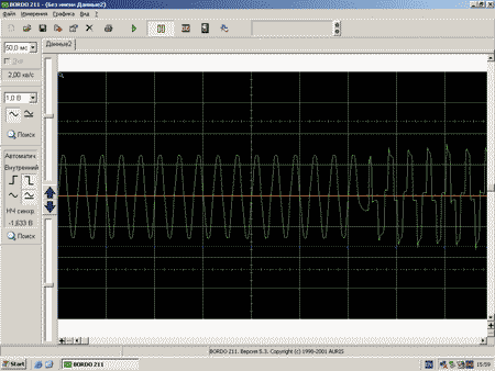
Rice. 4. Switch to battery power
After the batteries were charged, the parameters of the output signal remained practically unchanged (Fig. 5); shutdown occurred without bursts; switching from battery power to mains power occurred without delay.

Rice. 5. Battery power mode APC Back-UPS ES 700VA
The operating time until the battery was completely discharged under a load with one computer and a 17-inch monitor was 41 minutes 22 seconds - this is more than enough to shut down the system correctly. Of the three models, the APC Back-UPS ES 700VA has the longest battery life, making it recommended for applications where external power is lost frequently and for extended periods of time.
This model costs a little more than the other two, but can nevertheless be recommended for use at home and in a small office. In addition, it should also be noted that the APC Back-UPS ES 700VA is equipped with excellent software, and that changing the battery is easy and simple. Separating sockets for different types of protection also facilitates operation and ensures longer operation of the built-in battery, since when powered by a battery it is impossible to connect more than four devices. Overall this perfect solution to protect several desktop personal computers from power surges.
The APC Back-UPS ES 525 model is a Line-Interactive UPS, has a non-sinusoidal output voltage and an output power of 525 VA (300 W). This model is made in a plastic case of an original shape and is somewhat different from the other two models. The top panel has a UPS on/off button, four EIC sockets for connecting the load, and an indicator light indicating the status of the device on this moment. The four load sockets are divided into two parts: three of them allow you to protect the connected equipment from voltage surges and maintain its operation in the absence of external power from the battery built into the UPS, and the fourth serves only to protect against voltage surges in the external network. The battery is located in a special niche at the bottom of the UPS under a cover that is secured with latches and is no different in design from the design in the other two models. On the side of the UPS there are RJ-45 connectors (input and output) for protection against surges in a computer or telephone network. Next to them is another special connector (RJ-45 with ten pins), to which the UPS control cable is connected. The other end of the cable connects to the computer via a USB port.

In addition to the Back-UPS ES 525, the delivery package of the device includes a cable for connecting to a computer, a telephone cable (RJ-11), an instruction manual, and a CD with software.
APC PowerChute Personal 2.0 software allows you to monitor operating parameters (input and output voltage, battery capacity (percentage), load level, etc.) and configure the UPS. Note that the Back-UPS ES 525 model, unlike the other two tested UPSs, supports a mode for monitoring the power of the connected load (Fig. 6). In addition, it supports a self-diagnosis function (testing the internal circuits of the UPS) and allows you to change the AVR (automatic voltage regulation) parameters. If desired, the user can set the rated output voltage when operating on batteries, as well as the operating mode of the AVR, selecting the moments when the voltage increase and decrease modes are turned on (step - 4 V). Changing these parameters makes it possible to configure the UPS to work with the power supply, which reduces the number of switchings and extends the life of both the UPS itself and the batteries. The remaining parameters do not differ in their settings from other tested models.

Rice. 6. Monitoring the power consumed by the load
During testing, the voltage boost stages of the AVR unit turned on when the input voltage dropped to 200 and 185 V, the output voltage was 230 V. When the input voltage increased to 250 V, the output voltage also increased to 250 V; at 255 V, the AVR worked, and the voltage dropped to 225 V. Switching to battery power mode occurred when the input voltage decreased to 165 V. In battery mode, with a load, the output voltage was 176 V, and in its absence - 220 V. Mode battery power was turned off when the input voltage increased to 190 V. It should be noted that the presence of an automatic control unit AVR voltage very useful in the conditions of Russian power grids, where the voltage can very often “sag” or, conversely, be very high compared to the nominal value. By the way, this model has a higher output voltage than the other two UPSs tested.
Switching to battery power was performed quickly (less than 6 ms) - fig. 7.

Rice. 7. Switch to power
from the APC Back-UPS ES 525 battery
At the end of the battery charge, the parameters of the output signal practically did not change (Fig. 8), the shutdown was performed without bursts, and the return to mains power occurred without delay.

Rice. 8. Battery power mode APC Back-UPS ES 525
The operating time until the battery was completely discharged under a load with one computer and a 17-inch monitor was 27 minutes 36 seconds, which is quite enough for the system to shut down correctly.
This model has a low price and therefore is quite suitable for use at home UPS and in a small office. Unlike the other two models reviewed, it is equipped with a built-in AVR unit, which has a positive effect on operation in Russian power grids and gives it an advantage over other models. The APC Back-UPS ES 525 has excellent software and a range of additional features on setup, and in addition, changing the battery is simple and convenient. Separating sockets for different types of protection also simplifies operation and extends the service life of the built-in battery.
The APC Back-UPS ES 525 UPS is awarded the “Editorial Recommend” mark for its wide functionality, stability in all modes and long-term battery operation in the absence of power.
Instead of a conclusion
Having considered three models from APC, we can say with confidence that these UPSs will be in demand in the market. Convenience and ease of operation, high reliability and pleasant appearance- all this should appeal to end users. Of the three models aimed at the end consumer, it is worth paying attention to the APC Back-UPS ES 525 model, which has a built-in automatic output voltage regulation (AVR) unit, which is very important for Russian power grids, where the voltage can either “sag” or and suddenly jump above acceptable limits.
The editors express their gratitude to APC for providing the APC Back-UPS ES 550VA, APC Back-UPS ES 700VA and APC Back-UPS ES 525 uninterruptible power supplies for testing.
The complete lack of information about such common devices as uninterruptible power supplies is surprising. We are breaking through the information blockade and are starting to publish materials on their design and repair. From the article you will get a general idea about existing types uninterruptible power supply and more detailed, at the level schematic diagram, - about the most common Smart-UPS models.
The reliability of computers is largely determined by the quality of the electrical network. Power outages such as surges, surges, dips, and loss of power may result in keyboard lockout, data loss, or damage to the motherboard etc. To protect expensive computers from troubles associated with the power network, uninterruptible power supplies (UPS) are used. A UPS allows you to get rid of problems associated with poor quality power supply or its temporary absence, but is not a long-term alternative source of power supply, like a generator.
According to the expert-analytical center "SK PRESS", in 2000, the sales volume of UPS at Russian market amounted to 582 thousand units. If we compare these estimates with data on computer sales (1.78 million units), it turns out that in 2000, every third computer purchased was equipped with an individual UPS.
The vast majority of the Russian UPS market is occupied by products from six companies: APC, Chloride, Invensys, IMV, Liebert, Powercom. APC products have been maintaining a leading position in the Russian UPS market for many years now.
UPSs are divided into three main classes: Off-line (or stand-by), Line-interactive and On-line. These devices have different designs and characteristics.
Rice. 1. Block diagram of an Off-line class UPS
The block diagram of an Off-line class UPS is shown in Fig. 1. During normal operation, the load is supplied with filtered mains voltage. To suppress electromagnetic and radio frequency interference in input circuits, EMI/RFI Noise filters are used on metal-oxide varistors. If the input voltage becomes lower or higher than the set value or disappears altogether, the inverter is turned on, which is normally in the off state. By converting the DC voltage of the batteries into alternating voltage, the inverter powers the load from the batteries. The shape of its output voltage is rectangular pulses of positive and negative polarity with an amplitude of 300 V and a frequency of 50 Hz. Off-line class UPSs operate uneconomically in electrical networks with frequent and significant voltage deviations from the rated value, since frequent switching to battery operation reduces the battery life. The power of the Back-UPS model Off-line class UPS produced by APC is in the range of 250...1250 VA, and the Back-UPS Pro model is in the range of 2S0...1400 VA.

Rice. 2. Block diagram of Line-interactive class UPS
The block diagram of a Line-interactive class UPS is shown in Fig. 2. Just like Off-line UPSs, they retransmit alternating mains voltage to the load, while absorbing relatively small voltage surges and smoothing out interference. The input circuits use Metal Oxide Varistor EMI/RFI Noise Filter to suppress EMI and RFI. If an accident occurs in the power grid, the UPS synchronously, without loss of the oscillation phase, turns on the inverter to power the load from the batteries, while the sinusoidal shape of the output voltage is achieved by filtering the PWM oscillation. The circuit uses a special inverter to recharge the battery, which also works during power surges. The range of operation without connecting a battery is expanded due to the use of an autotransformer with a switchable winding in the input circuits of the UPS. The switch to battery power occurs when the mains voltage goes out of range. The power of Line-interactive UPS class Smart-UPS manufactured by APC is 250...5000 VA.
Rice. 3. Block diagram of an On-line class UPS
The block diagram of an On-line class UPS is shown in Fig. 3. These UPSs convert AC input voltage to DC, which is then converted back into AC with stable parameters using a PWM inverter. Since the load is always supplied by the inverter, there is no need to switch from the external network to the inverter, and the switching time is zero. Due to the inertial link direct current, which is a battery, the load is isolated from network anomalies and a very stable output voltage is generated. Even with large deviations in input voltage, the UPS continues to supply the load with pure sinusoidal voltage with a deviation of no more than +5% from the user-set nominal value. APC On-line class UPSs have the following output powers: Matrix UPS models - 3000 and 5000 VA, Symmetra Power Array models - 8000, 12000 and 16000 VA.
Back-UPS models do not use a microprocessor, but Back-UPS Pro, Smart-UPS, Smart/VS, Matrix and Symmetna models do use a microprocessor.
The most widely used devices are: Back-UPS, Back-UPS pro, Smart-UPS, Smart-UPS/VS.
Devices such as Matrix and Symmetna are used primarily for banking systems.
In this article, we will look at the design and circuit of Smart-UPS 450VA...700VA models used to power personal computers (PCs) and servers. Their technical characteristics are given in table. 1.
Table 1. Specifications Smart-UPS models from APC
| Model | 450VA | 620VA | 700VA | 1400VA |
|---|---|---|---|---|
| Allowable input voltage, V | 0...320 | |||
| Input voltage when operating from the network *, V | 165...283 | |||
| Output voltage *, V | 208...253 | |||
| Input circuit overload protection | Returnable to initial position circuit breaker | |||
| Frequency range when operating from mains, Hz | 47...63 | |||
| Switching time to battery power, ms | 4 | |||
| Maximum load power, VA (W) | 450(280) | 620(390) | 700(450) | 1400(950) |
| Output voltage when operating on battery, V | 230 | |||
| Frequency when operating on battery power, Hz | 50 ± 0.1 | |||
| Waveform when running on battery | Sine wave | |||
| Output circuit overload protection | Overload and short circuit protection, latching switch off when overloaded | |||
| Battery Type | Lead sealed, maintenance free | |||
| Number of batteries x voltage, V, | 2 x 12 | 2 x 6 | 2 x 12 | 2 x 12 |
| Battery capacity, Ah | 4,5 | 10 | 7 | 17 |
| Battery life, years | 3...5 | |||
| Full charge time, h | 2...5 | |||
| UPS dimensions (height x width x length), cm | 16.8x11.9x36.8 | 15.8x13.7x35.8 | 21.6x17x43.9 | |
| Net weight (gross), kg | 7,30(9,12) | 10,53(12,34) | 13,1(14,5) | 24,1(26,1) |
* User adjustable via PowerChute software.
UPS Smart-UPS 450VA...700VA and Smart-UPS 1000VA...1400VA have the same electrical diagram and differ in battery capacity, number of output transistors in the inverter, power power transformer and dimensions.
Let's consider the parameters characterizing the quality of electricity, as well as terminology and designations.
Power problems can be expressed as:
In Russia, dips, dropouts and voltage surges, both up and down, account for approximately 95% of deviations from the norm, the rest is noise, impulse noise (needles), and high-frequency surges.
The units used to measure power are Volt-Amps (VA, VA) and Watts (W, W). They differ in power factor PF (Power Factor):
The power factor for computer equipment is 0.6...0.7. The number in the designation of APC UPS models means maximum power in VA. For example, the Smart-UPS 600VA model has a power of 400 W, and the 900VA model has a power of 630 W.
The block diagram of the Smart-UPS and Smart-UPS/VS models is shown in Fig. 4. The mains voltage is supplied to the EM/RFI input filter, which serves to suppress interference from the mains. At the rated mains voltage, relays RY5, RY4, RY3 (pins 1, 3), RY2 (pins 1, 3), RY1 are turned on, and the input voltage passes to the load. Relays RY3 and RY2 are used for the BOOST/TRIM output voltage adjustment mode. For example, if the network voltage has increased and gone beyond the permissible limit, relays RY3 and RY2 connect the additional winding W1 in series with the main winding W2. An autotransformer is formed with a transformation ratio
K = W2/(W2 + W1)
less than one, and the output voltage drops. In the event of a decrease in the mains voltage, the additional winding W1 is reversed by the relay contacts RY3 and RY2. Transformation ratio
K = W2/(W2 - W1)
becomes greater than unity, and the output voltage increases. The adjustment range is ±12%, the hysteresis value is selected by the Power Chute program.
When the input voltage fails, relays RY2...RY5 are turned off, a powerful PWM inverter powered by the battery is turned on, and a sinusoidal voltage of 230 V, 50 Hz is supplied to the load.
The multi-link power supply noise suppression filter consists of varistors MV1, MV3, MV4, inductor L1, capacitors C14...C16 (Fig. 5). Transformer CT1 analyzes high-frequency components of the network voltage. Transformer CT2 is a load current sensor. Signals from these sensors, as well as the temperature sensor RTH1, are sent to the analog-to-digital converter IC10 (ADC0838) (Fig. 6).
Transformer T1 is an input voltage sensor. The command to turn on the device (AC-OK) is sent from the two-level comparator IC7 to the base Q6. Transformer T2 - output voltage sensor for Smart TRIM/BOOST mode. From pins 23 and 24 of processor IC1 2 (Fig. 6), the BOOST and TRIM signals are supplied to the bases of transistors Q43 and Q49 to switch relays RY3 and RY2, respectively.
The phase synchronization signal (PHAS-REF) from pin 5 of transformer T1 goes to the base of transistor Q41 and from its collector to pin 14 of the IC12 processor (Fig. 6).
The Smart-UPS model uses an IC12 microprocessor (S87C654) that:
The EEPROM IC13 memory chip stores factory settings, as well as calibrated settings for frequency signal levels, output voltage, transition limits, and battery charging voltage.
Digital-to-analog converter IC15 (DAC-08CN) generates a reference sinusoidal signal at pin 2, which is used as a reference for IC17 (APC2010).
The PWM signal is generated by IC14 (APC2020) together with IC17. Powerful field effect transistors Q9...Q14, Q19...Q24 form a bridge inverter. During the positive half-wave of the PWM signal, Q12...Q14 and Q22...Q24 are open, and Q19...Q21 and Q9...Q11 are closed. During the negative half-wave, Q19...Q21 and Q9...Q11 are open, and Q12...Q14 and Q22...Q24 are closed. Transistors Q27...Q30, Q32, Q33, Q35, Q36 form push-pull drivers that generate control signals for powerful field-effect transistors with a large input capacitance. The load of the inverter is the transformer winding, it is connected by wires W5 (yellow) and W6 (black). A sinusoidal voltage of 230 V, 50 Hz is generated on the secondary winding of the transformer to power the connected equipment.
Operation of the inverter in “reverse” mode is used to charge the battery with pulsating current during normal operation of the UPS.
The UPS has a built-in SNMP slot, which allows you to connect additional cards to expand the capabilities of the UPS:
The UPS has several voltages necessary for normal operation of the device: 24 V, 12 V, 5 V and -8 V. To check them, you can use the table. 2. Measure the resistance from the terminals of the microcircuits to the common wire with the UPS turned off and capacitor C22 discharged. Typical faults UPS Smart-Ups 450VA...700VA and methods for their elimination are given in table. 3.
Table 3. Typical faults of Smart-Ups 450VA...700VA UPS
| Brief description of the defect | Possible reason | Troubleshooting method |
|---|---|---|
| UPS does not turn on | Batteries not connected | Connect batteries |
| Bad or faulty battery, its capacity is low | Replace the battery. The capacity of a charged battery can be checked using a high beam lamp from a car (12 V, 150 W) | |
| Powerful field-effect transistors of the inverter are broken | In this case, there is no voltage at the terminals of the battery connected to the UPS board. Check with an ohmmeter and replace the transistors. Check the resistors in their gate circuits. Replace IC16 | |
| Broken flexible cable connecting the display | This problem may be caused by the flex cable terminals shorting on the UPS chassis. Replace the flexible cable connecting the display to the main board of the UPS. Check the serviceability of fuse F3 and transistor Q5 | |
| The power button is pressed in | Replace button SW2 | |
| The UPS turns on only from the battery | Fuse F3 burned out | Replace F3. Check the serviceability of transistors Q5 and Q6 |
| The UPS does not start. Battery replacement indicator lights up | If the battery is good, the UPS does not execute the program correctly. | Calibrate the battery voltage using a proprietary program from APC |
| The UPS does not connect to the line | Torn off network cable or contact is broken | Connect the network cable. Check the serviceability of the automatic plug with an ohmmeter. Check the hot-neutral cord connection |
| Cold soldering of board elements | Check the serviceability and quality of soldering of elements L1, L2 and especially T1 | |
| Varistors are faulty | Check or replace varistors MV1...MV4 | |
| When the UPS is turned on, the load is shed | Voltage sensor T1 is faulty | Replace T1. Check the serviceability of the elements: D18...D20, C63 and C10 |
| Display indicators are flashing | The capacitance of capacitor C17 has decreased | Replace capacitor C17 |
| Possible capacitor leakage | Replace C44 or C52 | |
| Relay contacts or board elements are faulty | Replace relay. Replace IC3 and D20. It is better to replace diode D20 with 1N4937 | |
| UPS overload | The power of the connected equipment exceeds the rated power | Reduce load |
| Transformer T2 is faulty | Replace T2 | |
| Current sensor ST1 is faulty | Replace ST1. Resistance greater than 4 ohms indicates a faulty current sensor | |
| IC15 is faulty | Replace IC15. Check voltage -8 V and 5 V. Check and replace if necessary: IC12, IC8, IC17, IC14 and power field-effect transistors of the inverter. Check the windings of the power transformer | |
| Battery won't charge | The UPS program is not working correctly | Calibrate battery voltage proprietary program from ARS. Check constants 4, 5, 6, 0. Constant 0 is critical for each UPS model. Check the constant after replacing the battery |
| The battery charging circuit is faulty | Replace IC14. Check the voltage of 8 V on the pin. 9 IC14, if it is missing, then replace C88 or IC17 | |
| Battery faulty | Replace the battery. Its capacity can be checked with a high beam lamp from a car (12 V, 150 W) | |
| Microprocessor IC12 is faulty | Replace IC12 | |
| When turned on, the UPS does not start, a clicking sound is heard | Reset circuit faulty | Check serviceability and replace faulty elements: IC11, IC15, Q51...Q53, R115, C77 |
| Indicator defect | Indication circuit is faulty | Check and replace faulty Q57...Q60 on the indicator board |
| The UPS does not work in On-line mode | Defective board elements | Replace Q56. Check the serviceability of the elements: Q55, Q54, IC12. IC13 is faulty or will need to be reprogrammed. The program can be taken from a working UPS |
| When switching to battery operation, the UPS turns off and turns on spontaneously | Transistor Q3 is broken | Replace transistor Q3 |
In the second part of the article, the On-line class UPS device will be considered,
OFF-LINE CLASS UPS DEVICE
Off-line UPSs from APC include Back-UPS models. UPSes of this class are low cost and are designed to protect personal computers, workstations, network equipment, trading and cash terminals. The power of produced Back-UPS models is from 250 to 1250 VA. Basic technical data of the most common UPS models are presented in table. 3.
Table 3. Basic technical data of Back-UPS class UPS
| Model | BK250I | BK400I | BK600I |
|---|---|---|---|
| Rated input voltage, V | 220...240 | ||
| Rated network frequency, Hz | 50 | ||
| Energy of absorbed emissions, J | 320 | ||
| Peak surge current, A | 6500 | ||
| IEEE 587 Cat. Voltage Surge Values Missed in Normal Mode. A 6kVA, % | <1 | ||
| Switching voltage, V | 166...196 | ||
| Output voltage when operating from batteries, V | 225 ± 5% | ||
| Output frequency when operating from batteries, Hz | 50 ± 3% | ||
| Maximum power, VA (W) | 250(170) | 400(250) | 600(400) |
| Power factor | 0,5. ..1,0 | ||
| Crest factor | <5 | ||
| Nominal switching time, ms | 5 | ||
| Number of batteries x voltage, V | 2x6 | 1x12 | 2x6 |
| Battery capacity, Ah | 4 | 7 | 10 |
| 90% recharge time after discharging to 50%, hour | 6 | 7 | 10 |
| Acoustic noise at a distance of 91 cm from the device, dB | <40 | ||
| UPS operating time at full power, min | >5 | ||
| Maximum dimensions (H x W x D), mm | 168x119x361 | ||
| Weight, kg | 5,4 | 9,5 | 11,3 |
The index “I” (International) in the names of UPS models means that the models are designed for an input voltage of 230 V. The devices are equipped with sealed lead-free maintenance-free batteries with a service life of 3...5 years according to the Euro Bat standard. All models are equipped with limiting filters that suppress surges and high-frequency interference in the mains voltage. The devices give appropriate sound signals when the input voltage is lost, the batteries are low, or there is an overload. The threshold value of the mains voltage, below which the UPS switches to battery operation, is set by switches on the rear panel of the device. Models BK400I and BK600I have an interface port that connects to a computer or server to automatically shut down the system, a test switch, and a buzzer switch.
The block diagram of the Back-UPS 250I, 400I and 600I is shown in Fig. 8. The mains voltage is supplied to the input multi-stage filter through a circuit breaker. The circuit breaker is designed as a circuit breaker on the rear panel of the UPS. In the event of a significant overload, it disconnects the device from the network, while the contact column of the switch is pushed upward. To turn on the UPS after an overload, it is necessary to return the contact column of the switch to its original position. The input filter-limiter of electromagnetic and radio frequency interference uses LC links and metal oxide varistors. During normal operation, contacts 3 and 5 of relay RY1 are closed, and the UPS transmits mains voltage to the load, filtering high-frequency interference. The charging current flows continuously as long as there is voltage in the network. If the input voltage drops below the set value or disappears altogether, or if it is very noisy, contacts 3 and 4 of the relay close, and the UPS switches to operation from the inverter, which converts the DC voltage of the batteries into AC. The switching time is about 5 ms, which is quite acceptable for modern switching power supplies for computers. The load signal shape is rectangular pulses of positive and negative polarity with a frequency of 50 Hz, a duration of 5 ms, an amplitude of 300 V, an effective voltage of 225 V. At idle, the duration of the pulses is reduced and the effective output voltage drops to 208 V. Unlike Smart models -UPS, Back-UPS does not have a microprocessor; comparators and logic chips are used to control the device.
The schematic diagram of the Back-UPS 250I, 400I and 600I UPS is almost completely shown in Fig. 9...11. The multi-link power supply noise suppression filter consists of varistors MOV2, MOV5, chokes L1 and L2, capacitors C38 and C40 (Fig. 9). Transformer T1 (Fig. 10) is an input voltage sensor. Its output voltage is used to charge batteries (D4...D8, IC1, R9...R11, C3 and VR1 are used in this circuit) and analyze the mains voltage.
If it disappears, then the circuit on elements IC2...IC4 and IC7 connects a powerful inverter powered by a battery. The ACFAIL command to turn on the inverter is generated by IC3 and IC4. A circuit consisting of comparator IC4 (pins 6, 7, 1) and electronic key IC6 (pins 10, 11, 12) allows the inverter to operate with a log signal. "1" arriving at pins 1 and 13 of IC2.
A divider consisting of resistors R55, R122, R1 23 and switch SW1 (pins 2, 7 and 3, 6), located on the rear side of the UPS, determines the mains voltage, below which the UPS switches to battery power. This voltage is factory set to 196 V. In areas where the mains voltage fluctuates frequently, resulting in frequent UPS transfers to battery power, the threshold voltage should be set to a lower level. Fine adjustment of the threshold voltage is performed by resistor VR2.
During battery operation, IC7 generates inverter excitation pulses PUSHPL1 and PUSHPL2. Power field-effect transistors Q4...Q6 and Q36 are installed in one arm of the inverter, and Q1...Q3 and Q37 in the other. The transistors are loaded with their collectors onto the output transformer. A pulse voltage with an effective value of 225 V and a frequency of 50 Hz is generated on the secondary winding of the output transformer, which is used to power the equipment connected to the UPS. The duration of the pulses is regulated by variable resistor VR3, and the frequency by resistor VR4 (Fig. 10). Turning the inverter on and off is synchronized with the mains voltage by a circuit on elements IC3 (pins 3...6), IC6 (pins 3...5, 6, 8, 9) and IC5 (pins 1...3 and 11... 13). Circuit based on elements SW1 (pins 1 and 8), IC5 (pins 4...V and 8...10), IC2 (pins 8...10), IC3 (pins 1 and 2), IC10 (pins 12 and 13), D30, D31, D18, Q9, BZ1 (Fig. 11) turns on an audible signal to warn the user of power problems. During battery operation, the UPS emits a single beep every 5 seconds to indicate the need to save user files because Battery capacity is limited. When operating on battery power, the UPS monitors its capacity and emits a continuous beep for a certain time before it is discharged. If pins 4 and 5 of switch SW1 are open, then this time is 2 minutes, if closed - 5 minutes. To turn off the sound signal, you need to close pins 1 and 8 of switch SW1.
All Back-UPS models, with the exception of the BK250I, have a bidirectional communication port for communication with a PC. Power Chute Plus software allows the computer to both monitor the UPS and securely automatically shut down the operating system (Novell, Netware, Windows NT, IBM OS/2, Lan Server, Scounix and UnixWare, Windows 95/98), preserving user files. In Fig. 11 this port is designated J14. Purpose of its pins: 1 - UPS SHUTDOWN. The UPS turns off if a log appears on this pin. "1" for 0.5 s.
2 - AC FAIL. When switching to battery power, the UPS generates a log on this pin. "1".
3 - CC AC FAIL. When switching to battery power, the UPS generates a log at this pin. "0". Open collector output.
4, 9 - DB-9 GROUND. Common wire for input/output signals. The output has a resistance of 20 Ohms relative to the common wire of the UPS.
5 - CC LOW BATTERY. In the event of a low battery, the UPS generates a log at this output. "0". Open collector output.
6 - OS AC FAIL When switching to battery power, the UPS generates a log on this pin. "1". Open collector output.
7, 8 - not connected.
Open collector outputs can be connected to TTL circuits. Their load capacity is up to 50 mA, 40 V. If you need to connect a relay to them, then the winding should be bypassed with a diode.
A regular “null modem” cable is not suitable for communication with this port; a corresponding RS-232 interface cable with a 9-pin connector is supplied with the software.
UPS CALIBRATION AND REPAIR
Setting the output voltage frequency
To set the frequency of the output voltage, connect an oscilloscope or frequency meter to the UPS output. Switch the UPS to battery mode. When measuring the frequency at the UPS output, adjust resistor VR4 to 50 ± 0.6 Hz.
Setting the output voltage value
Switch the UPS into battery mode without load. Connect a voltmeter to the UPS output to measure the effective voltage value. By adjusting resistor VR3, set the voltage at the UPS output to 208 ± 2 V.
Setting the threshold voltage
Set switches 2 and 3 located on the rear side of the UPS to the OFF position. Connect the UPS to a transformer type LATR with continuously adjustable output voltage. Set the voltage at the LATR output to 196 V. Turn resistor VR2 counterclockwise until it stops, then slowly turn resistor VR2 clockwise until the UPS switches to battery power.
Setting the charge voltage
Set the voltage at the UPS input to 230 V. Disconnect the red wire going to the positive terminal of the battery. Using a digital voltmeter, adjust the resistor VR1 to set the voltage on this wire to 13.76 ± 0.2 V relative to the common point of the circuit, then restore the connection to the battery.
Typical faults
Typical faults and methods for eliminating them are given in table. 4, and in table. 5 - analogues of the most frequently failing components.
Table 4. Typical Back-UPS 250I, 400I and 600I faults
| Defect manifestation | Possible reason | Method for finding and eliminating a defect |
|---|---|---|
| Smell of smoke, UPS does not work | Input filter faulty | Check the serviceability of components MOV2, MOV5, L1, L2, C38, C40, as well as the board conductors connecting them |
| The UPS does not turn on. The indicator does not light up | Input circuit breaker (circuit breaker) of the UPS is disabled | Reduce the load on the UPS by turning off part of the equipment, and then turn on the circuit breaker by pressing the circuit breaker contact column |
| Batteries are faulty | Replace batteries | |
| Batteries are not connected correctly | Check that the batteries are connected correctly | |
| Inverter faulty | Check the serviceability of the inverter. To do this, disconnect the UPS from the AC mains, disconnect the batteries and discharge capacitance C3 with a 100 Ohm resistor, test the drain-source channels of powerful field-effect transistors Q1...Q6, Q37, Q36 with an ohmmeter. If the resistance is several ohms or less, then replace the transistors. Check the resistors in the gates R1...R3, R6...R8, R147, R148. Check the serviceability of transistors Q30, Q31 and diodes D36...D38 and D41. Check fuses F1 and F2 | |
| Replace IC2 | ||
| When turned on, the UPS switches off the load | Transformer T1 is faulty | Check the serviceability of the windings of transformer T1. Check the tracks on the board connecting the T1 windings. Check fuse F3 |
| The UPS operates on batteries despite the fact that there is mains voltage | The power supply voltage is very low or distorted | Check the input voltage using an indicator or meter. If this is acceptable for the load, reduce the sensitivity of the UPS, i.e. change the response limit using switches located on the rear wall of the device |
| The UPS turns on, but no voltage is supplied to the load | Relay RY1 is faulty | Check the serviceability of relay RY1 and transistor Q10 (BUZ71). Check the serviceability of IC4 and IC3 and the supply voltage at their terminals |
| Check the tracks on the board connecting the relay contacts | ||
| The UPS hums and/or shuts down the load without providing the expected backup time | The inverter or one of its elements is faulty | See sub-item “Inverter faulty” |
| UPS does not provide expected power backup time | Batteries are discharged or have lost capacity | Charge the batteries. They require recharging after prolonged power outages. In addition, batteries age quickly when used frequently or in high temperature environments. If the batteries are approaching the end of their service life, it is advisable to replace them, even if the battery replacement alarm has not yet sounded. Check the capacity of the charged battery with a 12 V, 150 W car high beam lamp |
| UPS is overloaded | Reduce the number of consumers at the UPS output | |
| UPS does not turn on after replacing batteries | Incorrect connection of batteries when replacing them | Check that the batteries are connected correctly |
| When turned on, the UPS emits a loud tone, sometimes with a decreasing tone | Defective or severely discharged batteries | Charge the batteries for at least four hours. If the problem persists after recharging, the batteries should be replaced. |
| Batteries are not charging | Diode D8 is faulty | Check the serviceability of D8. Its reverse current should not exceed 10 μA |
| Charge voltage below required level | Calibrate battery charge voltage |
Table 5. Analogues for replacing faulty components
| Circuit designation | Faulty component | Possible replacement |
|---|---|---|
| IC1 | LM317T | LM117H, LM117K |
| IC2 | CD4001 | K561LE5 |
| IC3, IC10 | 74С14 | It is made up of two K561TL1 microcircuits, the conclusions of which are connected according to the pinout on the microcircuit |
| IC4 | LM339 | K1401SA1 |
| IC5 | CD4011 | K561LA7 |
| IC6 | CD4066 | K561KT3 |
| D4...D8, D47, D25...D28 | 1N4005 | 1N4006, 1N4007, BY126, BY127, BY133, BY134, 1N5618... 1N5622, 1N4937 |
| Q10 | BUZ71 | BUZ10, 2SK673, 2SK971, BUK442...BUK450, BUK543...BUK550 |
| Q22 | IRF743 | IRF742, MTP10N35, MTP10N40, 2SK554, 2SK555 |
| Q8, Q21, Q35, Q31, Q12, Q9, Q27, Q28, Q32, Q33 | PN2222 | 2N2222, BS540, BS541, BSW61...BSW 64, 2N4014 |
| Q11, Q29, Q25, Q26, Q24 | PN2907 | 2N2907, 2N4026...2N4029 |
| Q1...Q6, Q36, Q37 | IRFZ42 | BUZ11, BUZ12, PRFZ42 |
Gennady Yablonin
"Electronic equipment repair"
A modern personal computer is a set of components that are quite expensive. That is why, if something burns out due to a power surge, the user himself will be to blame, and not the power grid. And the careless PC owner will have to tear his hair out. After all, all you had to do was buy a source and all components of the system would remain safe and sound. The UPS not only keeps the computer running during a power outage, but also stabilizes the incoming current, preventing sudden voltage surges. And now we’ll talk about the APC Back-UPS ES 700. This is a good budget solution for the home.
A little about the company
The APC company was founded back in 1981 on the basis of the Massachusetts Institute of Technology. It specialized in the production of voltage stabilizers and uninterruptible power supplies. The company existed in this form until 2007. And then it was bought by the French engineering company Shneider Electric. And now ARS is a subsidiary that produces uninterruptible power supplies for the needs of users.

The company's entry into the Schneider concern did not in any way affect its productivity. Its products are still supplied to the market and enjoy the same popularity among owners of personal computers. The developer’s arsenal includes a variety of models for various needs: from simple blocks to multifunctional combines. The APC Back-UPS ES 700 uninterruptible power supply is a budget option and is suitable for almost everyone. Let's look at it in more detail.
Contents of delivery
The uninterruptible power supply comes in an inconspicuous box made from recycled cardboard. Inside there is the unit itself, a user manual, a warranty card, a bunch of unnecessary papers about safe operation, a connecting cable for connecting to a computer, a 62PC telephone cable and a disk with drivers and software. As you can see, everything is quite strict. Designed in the signature minimalist style of ARS. An interesting thing is lifetime insurance from the manufacturer. It's also included in the kit. According to this document, the company provides a lifetime warranty on its products. And if any component fails, you should send the entire device to the manufacturer (at your own expense) and they will send you a new one. And who will do this for us? It's easier to buy a new one.

The most interesting thing is that the user manual includes Russian. This is a sign that the manufacturing company is truly reputable and wants people to trust it. Many people neglect language support. But not ARS.
Appearance and Design
The APC Back-UPS ES 700 uninterruptible power supply looks like a black plastic box with a bunch of connectors for connecting PC power cables. The body is completely made of durable plastic. The device's battery is hidden at the bottom of the case. Thanks to him, the device turned out to be heavy. There is nothing interesting in the appearance of this UPS. The corporate style of ARS is felt. But nothing more. You can't get much out of design. So it’s better to go straight to the technical specifications.
Specifications
The maximum input voltage going to the device should be 230 Volts. No more. Otherwise, the uninterruptible power supply will not hold up. And no voltage rectifier will help. In this case, the UPS produces a direct current of 230 Volts with all corrections. The output power of the unit is 405 Watt. The operating time of a personal computer from the UPS battery depends on the configuration of the system unit. But the average figures are as follows: at half load - 15 minutes, at full load - 4 minutes. The indicators are average. What was expected at such and such a price.

If the Back-UPS ES 700 beeps, there is something wrong with the battery. The unit is equipped with a special indicator, which also shows if there are problems with the battery. But it can be easily replaced with a new one. Finding the same cartridge will not be difficult. Some “craftsmen” even manage to install car batteries in this UPS. And what? Perfect solution. They live longer. But it is still better to use original components.
Owner reviews
Reviews are incredibly important when choosing a product. They can show how the device behaves in real conditions and how reliable it is. And in the case of uninterruptible power supplies, the last factor is especially important. So what do users say about the APC Back-UPS ES 700 UPS? The price is the first thing that pleased people. It really doesn't cost much. Many owners note the long battery life and built-in technology that prevents the battery from wearing out quickly. The unit operates quietly and is not annoying. It starts to make noise only when it switches to autonomous power supply. In general, almost all owners of this device are satisfied with its performance. And this is the most important thing.

However, there were also dissatisfied comrades. For some, the battery died immediately. Apparently, they came across a device with a manufacturing defect. There were some other complaints about the UPS ES 700. The battery, for example, did not want to be charged. But these are all isolated cases. The owners of ancient computers were especially amused when they said that they did not install drivers. Of course, if they are still running Windows 2000, then this is very likely. You need to carefully read the device specifications. And then such questions will not arise. You also need to operate the uninterruptible power supply correctly and safely. And then there will be no problems with him at all.
Operating rules
In order for the APC Back-UPS ES 700 uninterruptible power supply to last as long as possible and not burn down your apartment, you need to follow basic rules of safe operation. Remember, never install an uninterruptible power supply near heating radiators. Especially in winter. It turns out that uninterruptible power supply batteries are a very delicate thing. When overheated, they flow, flood those parts of the UPS that are energized, and those, in turn, burn out. And it’s good if the body doesn’t melt. So do not place your Back-UPS ES 700 near batteries. The instructions in Russian will probably warn you about this. But who reads it?

Another rule is that pets are not allowed near the uninterruptible power supply. If your cat or dog decides to chew the wires of the uninterruptible power supply, then there are two options for the development of this situation. In the first of them, your pet will be shocked by an electric shock and all subsequent actions to resuscitate it will be useless. In the second option, a short circuit will occur and then a fire. In accordance with all the laws of the genre. Do not let animals play with live devices. It is important.
Features of replacing a device under warranty
The APC company has a very specific vision of the warranty service procedure. They strictly prohibit users from contacting the seller of the uninterruptible power supply. They invite users to send them the damaged device themselves, and the company will send another in return. New. Well, who will do this for us? Especially considering that you will have to send the uninterruptible power supply at your own expense. And our prices for postal services are not particularly encouraging. Moreover, you will have to send it all the way to the USA.

So, we can say with confidence that APC products do not have warranty service as such. At least for our country. After all, imagining our person sending a faulty device somewhere at his own expense is simply beyond imagination. But usually there are no problems with uninterruptible power supplies from APC. And if they do occur, then the sellers meet the customer halfway and replace the defective product themselves.
Conclusion
The APC Back-UPS ES 700 uninterruptible power supply is the optimal solution for home and office. It is easy to use, unpretentious in operation and inexpensive. And the last factor may be decisive for many. The uninterruptible power supply showed itself perfectly when working in real conditions. It’s also nice that the user manual is in Russian. You just need to follow the rules of safe operation. And then the device will work faithfully for quite a long time.


