Ignition coil(or ignition module) - an element of the car’s ignition system that converts low-voltage voltage on-board network into a high voltage pulse. The high voltage that occurs in causes a spark to form between the electrodes of the spark plug and ensures the ignition of the fuel-air mixture.
Ignition coil device
The ignition coil is a transformer with two windings: primary and secondary, inside of which there is a steel core and an insulated housing outside.
- The primary winding consists of thick copper insulated wire and has from 100 to 150 turns. The winding has 12 volt terminals.
- The secondary winding is usually located outside the primary. It consists of 15,000-30,000 turns of thin copper wire. This system is typical for both the ignition module, a dual-type ignition coil, and an individual coil. A. A pulse voltage of up to 35,000 volts is created in the secondary winding, which is supplied to the spark plugs.
Operating principle of the ignition coil
A low voltage voltage is supplied to the primary winding of the coil, which creates a magnetic field. From time to time, this voltage is cut off by a breaker, causing a sharp reduction in the magnetic field and the formation of an electromotive force (emf) in the turns of the coils.
According to the physical law of electromagnetic induction, the magnitude of the emf thus generated. is directly proportional to the number of turns of the circuit winding. Therefore, a high-voltage pulse is generated in the secondary coil with a large number of turns, which is supplied to the spark plug through high-voltage wires (not applicable to an individual ignition coil installed directly on the spark plug). Thanks to the impulse transmitted by the coil, a spark is formed between the electrodes of the spark plug, which ignites the fuel-air mixture.
In older car models, voltage from the ignition coil was supplied to all spark plugs using an ignition distributor. This scheme turned out to be not reliable enough, so the ignition coils (they are also called spark plugs) modern car combined into a system and distributed one for each candle.
Types of car ignition coils
There are common and individual ignition coils.
- A common ignition coil is used in ignition systems with or without a distributor. Its design is described above: the primary winding is located outside the secondary, inside which there is a core. The core coils are enclosed in a steel housing. The pulse from the secondary winding is supplied to the spark plugs.
- A custom ignition coil is used in direct electronic ignition systems. Unlike the common design, in individual coils the primary winding is located inside the secondary. The individual coil is installed directly on the spark plug, so the high-voltage pulse is transmitted with virtually no loss of power.
1. Do not leave the ignition on without starting the engine for for a long time. This significantly reduces the life of the ignition coils.
2. Take the time to clean and check the condition of the coil. Make sure that the wire fastenings are in order, it is especially important to check the high-voltage wire. Also make sure that no water gets on or into the housing.
3. Do not disconnect the high-voltage wire from the coil with bare hands when the ignition is on.
Purpose of the ignition coil
The ignition coil is one of the most important elements for igniting fuel in the engine cylinders. It is a device that consumes low-voltage current from a car battery and converts it into high-voltage pulses. They're in right moment form a spark between the spark plug electrodes and ignite the fuel-air mixture.
Design
The design of the ignition coil is similar to a transformer: it also has two windings (primary and secondary) on the core, and a special device converts the direct current of the battery into pulsed current, the voltage of which increases several thousand times according to the law of electromagnetic induction. In the ignition systems of older cars there was only one such unit. Pulses from it were supplied in turn to all the spark plugs through a distributor and high-voltage wires. But lately, a system with a separate coil for each cylinder is becoming increasingly common on cars.
Diagnostics by shorting the spark plug to the body
Without of this device the car is unable to start. Therefore, checking the ignition coil is an operation that any motorist should be able to perform. The most common method is to unscrew the spark plugs from the cylinder and short them to the engine housing and then try to start the car. If a spark jumps between the electrodes, it means the ignition coil is working. If not, then most likely the problem is with this device. But many car enthusiasts have the opinion that with this method of checking the ignition coil can be damaged.
Diagnostics by resistance measurement method

There is a safe alternative, but in this case you will need an ohmmeter. The method consists of measuring the resistance of the windings. Their exact values are indicated in technical reference books, but usually the working ignition coil has a resistance of 16-17 KOhm on the primary winding. If a strong discrepancy with this figure or even a break (infinite resistance) or short circuit (the value will tend to zero) is detected, then most likely this unit is faulty.
Alternative diagnostic methods
Another way is to install your reel on another machine. In this case, you will definitely know whether this component is working properly. The difficulty is that the car must be the same brand and configuration as yours, and you also need the consent of its owner. There are also visual signs of coil failure: the smell of burnt insulation or traces of breakdown (the presence of black burnt spots on the body and windings).
Is it possible to repair the ignition coil?
What to do if a malfunction of this component of the ignition system is determined? Just change it - the coil cannot be repaired. More precisely, it can be repaired, but the complexity of replacing the windings makes such an operation unprofitable.

Work methodology
Remember safety precautions during all manipulations with the ignition system, since the coil voltage can reach 20-25 thousand volts. Use tools with electrically insulated handles and do not work in damp areas or in the rain. If you cannot find the cause of the car malfunction yourself, contact a specialized service. Good luck on the roads!
This is perhaps the only vehicle electrical equipment that has not changed in principle of use since the inception of battery ignition systems. Only management methods have improved. And alternatives to the coil look fantastic, unrealizable and even aurally unreliable, for example, laser system ignition Although ignition systems based on piezo transformers have their place, they have their own problems, and are more often used in compact systems ignition
We should also mention “capacitor” ignition systems, but they cannot compete with “coil” ignition systems either in cost or reliability (due to the complexity of the design).
WATCH THE VIDEO
An ignition coil is an electrical device that converts low voltage from the vehicle's on-board network into high voltage pulses. These pulses create a spark between the spark plug electrodes. The spark ignites the mixture in the engine cylinders.
The main task of the ignition coil is to provide the spark plug current necessary to ensure guaranteed ignition of the fuel-air mixture.
Existing types of ignition coils for different engine types (up to 16 valves)
Modern ignition coils can be divided into several types:
- working for all candles - common;
- for one spark plug – individual (for a four-cylinder engine, for example – four ignition coils).
Individual ignition coils are used mainly on engines with 16 valves (more precisely, on engines that have more than 2 valves per cylinder), because this application easily allows you to adjust the ignition timing not just per revolution, but also from spark plug to spark plug, which serves as a way forcing or supporting abnormal engine operation. Yes, and they are installed in spark plug wells between the camshafts, which, in fairness, does not improve their durability due to the thermal regime.
- For two spark plugs - two-spark (four-cylinder engine - system of 2 ignition coils). It has a built-in switch inside (which is responsible for adjusting the times necessary for normal operation of the coil) or simply an ignition amplifier (which only amplifies commands from the control unit);
- double-spark ones can be structurally connected into ignition units. So the price and dimensions (relative to just two-spark coils) of the ignition system are reduced. Although the high-voltage wire and tip for each cylinder remain, the connection to the engine management system is simplified.
Coil arrangement diagram
Strictly speaking, ignition coil is slang for car enthusiasts. For radio amateurs, the coil is a simple inductance, but what they install in cars is a transformer. Transformer that converts pulses low voltage into high voltage pulses.
The ignition coil design is not too complicated. The transformer can be with an open core, something like a Ruhmkorff coil. Such reels were called “bobbins”. It’s just that when disassembling such an ignition coil, there was nothing interesting inside except for a coil of very thin wire (hundredths of a millimeter in diameter) on a package of metal plates. The coil can also be with a closed core, these are the ones that have become widespread recently.
So, how does the “reel” work:
- Lid.
- Contact socket.
- Screw.
- Low voltage output.
- Sealing gasket.
- Ring magnetic circuit.
- Primary winding.
- Secondary winding.
- Porcelain insulator.
- Coil housing.
- Transformer oil.
- Core.
- Cardboard gasket.
- Contact spring.
A modern individual ignition coil consists of the following components (in the diagram):
And this is what the diagram of a two-spark coil looks like:
- High voltage output to the first spark plug.
- High voltage output to the second spark plug.
- Pouring mass.
- Low voltage terminals.
- Iron core.
- Primary winding.
- Secondary winding.
Principle of operation
Let's consider the principle of operation of the device.
One end of the primary winding is connected to circuit 15 of the car (+ after the ignition switch). The second end goes to the switching element, mechanical contact or transistor. When the contact is closed, the increasing current in the primary winding causes an increase in the magnetic field in the coil core.
This is the process of energy accumulation. When the primary circuit contact opens, the accumulated magnetic field energy is released through the secondary winding into the spark gap of the high-voltage ignition system circuit. That is, the energy of the ignition coil or, in other words, the high voltage from the ignition coil through the armored wires causes a spark between the electrodes of the spark plug.
In principle, the circuit for connecting the ignition coil in the electrical circuit of a car is a flyback converter. Why the converter is clear. Why flyback? Because the ignition coil works at the moment when, in fact, they stop supplying energy to it. On the "reverse" move.
Why is it done this way? Because it takes time to accumulate energy in the coil. And the time to produce a spark with other switching principles strongly depends on the size of the total spark gap in the spark circuit. Those. The ignition timing will fluctuate greatly.
Have high volatility, as it is now fashionable to say. And since the task of the device is to provide a spark of guaranteed energy in a guaranteed time, this principle of spark formation was chosen. Also in systems with individual coils, this reduces the amount of copper used as the primary winding because its inductance can be raised due to the greater possible time for energy storage.
2-spark devices
A 2-spark ignition coil operates with one difference from a single-spark (general or individual). Both terminals of the secondary winding are designed for connecting spark plugs. Those. During one cycle of operation, a spark jumps in two spark plugs. And the spark plugs are selected accordingly in the cylinders, in one of which the power stroke occurs, and in the second the intake cycle begins.
The use of such an operating scheme requires additional design solutions, which, oddly enough, increases the life of the coil. In this design, it is easy to provide a large gap between the high-voltage winding and the vehicle mass, which facilitates the work of the winding dielectric. And it is easy to move the core outside the winding housing, which unifies the ignition coil with other winding electronic devices, which reduces the price of the device.
Reel prices
Pricing of ignition coils mainly depends on their design features and device diagrams. In particular, combining two-spark coils into blocks allows not only to reduce the final dimensions of the device, but also to reduce its cost.
Possible faults
There are not so many malfunctions in the ignition coil. Let us distinguish two classes: malfunctions due to which the spark is lost altogether, and malfunctions due to which the spark parameters do not allow the engine to operate normally.
WATCH THE VIDEO
In general, there may be no spark for the following reasons (with other equipment in good working order, i.e. the primary circuit of the ignition coil is working):
- break of the primary winding;
- complete closure of the primary winding;
- burnout of built-in electronics (if any).
Here are the reasons for the loss of spark parameters:
- interturn short circuit of the primary winding;
- interturn short circuit of the secondary winding;
- break of the secondary winding (yes, yes, break of the secondary winding - it simply gives an additional spark gap to the general spark gap of the high-voltage ignition circuit and for some time, often quite a long time, the car can work outwardly quite normally);
- breakdown in the high-voltage circuit of the coil (the spark energy will be sufficient, but the gap being broken through will be insufficient for the spark plugs to operate under heavy engine operating conditions);
- loss of operating parameters of the built-in electronics.
If in the first case there is no spark at all, then in the second case there may be a “floating” fault. Those. the malfunction does not appear systematically. These are difficult to catch, although there is a common sign - an abnormally high temperature of the ignition coil.
Algorithm for replacing the ignition coil on a Lada Priora
WATCH THE VIDEO
Replacing one or more ignition coils is subject to general principles. Let's look at the example of a Lada Priora car:
- you need to make sure that the car's ignition is turned off (for any car);
- remove the top cover of the engine protection (if there is one, unscrew or snap off the clips);
- remove the connector going from the computer to the individual ignition coil;
- unscrew the bolt holding it;
- we remove the faulty individual module from the spark plug well;
- insert a working coil into the free space;
- tighten the fastening bolt back;
- screw/snap the top cover of the engine protection.
Replacing coils on engines (on Nissan, Chevrolet, Honda, Ford, Opel, Renault Logan or Peugeot cars)
The process of replacing coils, in general, follows the same algorithm on cars of all brands, since the principle of their installation and operation is the same. Therefore, if you need to replace the device, you can rely on the general rules indicated above.
Functionality check
It is quite easy to check the functionality of the coil in the ignition system. A slight difficulty arises when checking individual ignition coils and modules. Next, we assume that our electronic engine control unit does not diagnose an open circuit in the module (otherwise we will have to do the following procedure simultaneously with all coils).
The main thing is to provide sufficient clearance in the high-voltage coil circuit to test the spark. If the coil is common, disconnect the armored wire from the ignition distributor and install a spark plug in it.
The candle is prepared as follows:
- we take a bolt or a piece of metal pin and screw it with electrical tape to one end of a block of some dielectric, dry wood, a piece of polypropylene heating pipe or the like;
- We screw the wire to this bolt and connect it to the ground of the car;
- We screw an old spark plug with a broken side electrode to the other end of the block so that the gap between the central electrode of the spark plug and the bolt is 8-11 mm for a contact ignition system, 22-25 mm for electronic systems ignition
Then we simply turn the engine with the starter. The spark should be clearly visible and preferably yellow in color.
If a spark is not visible, but clicks are heard, there is probably a breakdown of the spark circuit to ground. If there are no clicks, both a break and a malfunction of the switching devices are likely.
To diagnose double-spark ignition coils, the device can be made from two spark plugs with broken side electrodes, with the required gap set. And there is no need to connect them to ground; it is even recommended to keep them away from the vehicle's mass during testing.
It is also not recommended to check the ignition coil for a spark by simply inserting a screwdriver and placing it on the engine. Since the engine shakes when starting, there is a possibility that the device will fall and high voltage will enter the car’s electronics, which is fraught. And it is impossible to set the spark gap in this way and maintain it during starting.
WATCH THE VIDEO
And another important condition: it is necessary to take into account that when checking individual or dual modules, it is necessary to interrupt the fuel supply to the engine. The easiest way to do this is to pull out the fuel pump fuse or disconnect the harness going to the fuel pump.
Other tests require certain knowledge and equipment, so we will not consider them. the main task- see the presence of a spark. For the rest, it’s better to turn to specialists.
The ignition coil is designed to create high voltage, which is then used by the spark plug to produce a spark. Therefore, its proper operation is necessary for the normal functioning of the ignition system. Essentially, the coil is a small transformer, the primary winding of which receives standard 12 V from the battery, and outputs a voltage of several kV. It is used in all ignition systems - contactless and electronic. The reasons for coil failure are typical. As a rule, this is a wire break, insulation damage, or mechanical deformation. Next, we will look at the signs of a malfunction and methods for diagnosing the ignition coil.
If the engine has individual coils installed, you can check them by replacing them with other spark plugs. In this case, it is better not to touch the wiring so as not to damage its integrity.

Ignition coil module
"Spark in a syringe" method

The process of checking the coil using such a homemade device is quite simple. To do this, you need to connect the coils one by one to the spark plug of the resulting “device”. Attach the crocodile fastener to the ground of the machine body. While changing the tested coils, the engine must be turned off and then restarted.
Initially, using a piston, you need to set the minimum gap between the wire on the piston and the electrode (1...2 mm). And by adjusting the distance from the wire on the piston to the electrode on the spark plug, visually watch the process of a spark appearing between them. The maximum distance in this case will be different for different cars, and it depends on the quality and condition of the spark plug, the condition of the car’s electrical system, the quality of the “mass” and other factors. Typically, a spark during such tests should appear at a distance between the electrodes from 1...2 mm to 5...7 mm.
Before each test of the operation of the resulting device, it is necessary to disconnect the connector from each injector so that fuel does not flood the cylinder during testing.
The main thing that can be accurately judged during such tests is a comparison of the condition of different coils by cylinder. If there is a malfunction or, this will be visible by the length of the spark compared to more or less serviceable coils.
Insulation resistance test
Another popular verification method is to measuring the wire insulation resistance value in the coil windings. To do this, you will need a multimeter that can measure resistance. It is better to remove the ignition coil from the car to make work more convenient. The measurement procedure is simple. The main thing is to know where the terminals of the primary and secondary coils are located, since measuring resistance must be checked on both of them.
Before starting work, make sure the multimeter is working properly. To do this, turn on the resistance measurement mode and connect the probes to each other. There should be 0 on the screen.
Two multimeter probes are connected (touched) in pairs to the terminals of the primary winding. The resistance value should be in the range of 0.5...3.5 Ohms (some coils may have more, you will find the exact information in the reference literature). A similar procedure must be carried out with the secondary coil. However, here the range of values will be different - from 6 to 15 kOhm (for similar information, check the reference literature).

Procedure for measuring the insulation resistance of the ignition coil
If the value is small, it means that the insulation in the winding is damaged, and you are dealing with a short, most likely interturn, circuit. If the resistance is too high, this means that the winding wire has broken and there is no normal contact. In any case, it is necessary to carry out repairs, that is, rewind the winding. However, in most cases it is better to simply replace ignition coil, since this method will save you from unnecessary hassle and costs. This applies to almost any car, because the cost of repairs will exceed the price of the coil itself.
If you are dealing with individual or two-terminal coils, then the situation here is somewhat different. The value on the primary winding should be similar. As for the “secondary”, the resistance value will be identical at both terminals. If a coil with four terminals is installed on the machine, then the check must be done on all terminals.
Also note that polarity is important when measuring secondary resistance. In particular, touch the central terminal (“ground”) with the black probe of the multimeter, and touch the tip rod with the red one.
The oscilloscope will show everything
The most professional method for checking a coil is to use an oscilloscope. Only he can give full information about the condition of the ignition system, and in particular the ignition coils. Therefore, in difficult cases it makes sense to use an electronic oscilloscope and an additional software. This is especially true when there is a so-called interturn short circuit on secondary voltage coils (with high voltage).
If you use an oscilloscope to take a graph of the operating voltage values in the dynamics (seen in the figure), then you can understand from it that the cause of the possible malfunctions described above will be the ignition coil. The fact is that when an interturn short circuit occurs in the secondary coil, the energy that could potentially be stored in this coil itself decreases, and this, in turn, leads to a decrease in the spark burning time, that is, misfire. This is especially noticeable when you sharply press the accelerator pedal.

The reel is intact

The coil is broken
Results
Checking the ignition coil is not difficult at all. Anyone, even a novice car enthusiast, can do this. The simplest and effective method- measurement of insulation resistance on the primary and secondary windings. To do this, it is better to remove the coil for ease of work.
Remember that when a malfunction is identified, it rarely makes sense to carry out repairs, in particular, to rewind one or the other winding. It is much easier to buy and replace a new entire ignition coil.
Welcome everyone to our website!
We continue to study electronics from the very beginning, that is, from the very basics, and the topic of today’s article will be operating principle and main characteristics of inductors. Looking ahead, I will say that first we will discuss theoretical aspects, and we will devote several future articles entirely to consideration of various electrical diagrams, which use inductors, as well as elements that we studied earlier in our course - and.
The design and principle of operation of an inductor.
As is already clear from the name of the element, an inductor, first of all, is just a coil :), that is, a large number of turns of an insulated conductor. Moreover, the presence of insulation is the most important condition– the turns of the coil should not be short-circuited with each other. Most often, the turns are wound on a cylindrical or toroidal frame:

The most important characteristic inductors is, naturally, inductance, otherwise why would it be given such a name :) Inductance is the ability to convert the energy of an electric field into the energy of a magnetic field. This property of the coil is due to the fact that when current flows through the conductor, a magnetic field appears around it:

And here’s what the magnetic field that appears when current passes through the coil looks like:

In general, strictly speaking, any element in an electrical circuit has inductance, even an ordinary piece of wire. But the fact is that the magnitude of such inductance is very insignificant, in contrast to the inductance of coils. Actually, in order to characterize this value, the Henry (H) unit of measurement is used. 1 Henry is actually a very large value, so µH (microhenry) and mH (milihenry) are most often used. Size inductance coils can be calculated using the following formula:
Let's figure out what kind of value is included in this expression:
It follows from the formula that as the number of turns or, for example, the diameter (and, accordingly, the cross-sectional area) of the coil increases, the inductance will increase. And as the length increases, it decreases. Thus, the turns on the coil should be placed as close to each other as possible, since this will lead to a decrease in the length of the coil.
WITH inductor device we figured it out, it's time to consider the physical processes that occur in this element when passing electric current. To do this, we will consider two circuits - in one we will pass direct current through the coil, and in the other - alternating current :)
So, first of all, let's figure out what happens in the coil itself when current flows. If the current does not change its value, then the coil has no effect on it. Does this mean that in case direct current Is the use of inductors not worth considering? But no :) After all, direct current can be turned on/off, and it’s at the moments of switching that all the most interesting things happen. Let's look at the circuit:

In this case, the resistor acts as a load; in its place there could be, for example, a lamp. In addition to the resistor and inductance, the circuit includes a DC source and a switch with which we will close and open the circuit.
What happens the moment we close the switch?
Coil Current will begin to change, since at the previous moment in time it was equal to 0. A change in current will lead to a change in the magnetic flux inside the coil, which, in turn, will cause the occurrence of EMF (electromotive force) of self-induction, which can be expressed as follows:
The occurrence of EMF will lead to the appearance of an induced current in the coil, which will flow in the direction opposite to the direction of the power source current. Thus, the self-induced emf will prevent current from flowing through the coil (the induced current will cancel the circuit current due to the fact that their directions are opposite). This means that at the initial moment of time (immediately after closing the switch) the current through the coil will be equal to 0. At this moment in time, the self-induction EMF is maximum. What will happen next? Since the magnitude of the EMF is directly proportional to the rate of change of current, it will gradually weaken, and the current, accordingly, on the contrary, will increase. Let's look at graphs that illustrate what we've discussed:

In the first graph we see circuit input voltage– the circuit is initially open, but when the switch is closed, a constant value appears. In the second graph we see change in current through the coil inductance. Immediately after closing the switch, the current is absent due to the occurrence of self-induction EMF, and then begins to gradually increase. The voltage on the coil, on the contrary, is at its maximum at the initial moment of time, and then decreases. The voltage graph across the load will coincide in shape (but not in magnitude) with the current graph through the coil (since in a series connection the current flowing through different elements of the circuit is the same). Thus, if we use a lamp as a load, they will not light up immediately after closing the switch, but with a slight delay (in accordance with the current graph).
A similar transient process in the circuit will be observed when the key is opened. A self-inductive emf will arise in the inductor, but the induced current in the event of an open circuit will be directed in the same direction as the current in the circuit, and not in the opposite direction, therefore the stored energy of the inductor will be used to maintain the current in the circuit:
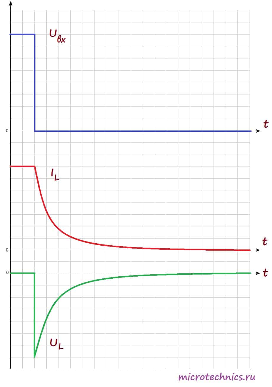
After the switch is opened, a self-induction emf occurs, which prevents the current through the coil from decreasing, so the current does not reach zero immediately, but after some time. The voltage in the coil is identical in shape to the case of closing the switch, but opposite in sign. This is due to the fact that the change in current, and accordingly the self-inductive emf in the first and second cases, is opposite in sign (in the first case, the current increases, and in the second it decreases).
By the way, I mentioned that the magnitude of the self-induction EMF is directly proportional to the rate of change of current, so the proportionality coefficient is nothing more than the inductance of the coil:
This concludes with inductors in DC circuits and moves on to chains alternating current .
Consider a circuit in which alternating current is supplied to the inductor:

Let's look at the dependences of current and self-induction EMF on time, and then we'll figure out why they look like this:

As we have already found out Self-induced emf we have a directly proportional and opposite sign of the rate of change of current:
Actually, the graph shows us this dependence :) See for yourself - between points 1 and 2 the current changes, and the closer to point 2, the smaller the changes, and at point 2 for a short period of time the current does not change at all its meaning. Accordingly, the rate of change of current is maximum at point 1 and smoothly decreases as it approaches point 2, and at point 2 it is equal to 0, which is what we see in self-induced emf graph. Moreover, over the entire interval 1-2, the current increases, which means the rate of its change is positive, and therefore the EMF across this entire interval, on the contrary, takes negative values.
Similarly, between points 2 and 3 - the current decreases - the rate of change of the current is negative and increases - the self-induction emf increases and is positive. I won’t describe the remaining sections of the graph - all processes there proceed according to the same principle :)
In addition, the graph shows very important point– with increasing current (sections 1-2 and 3-4), the self-induction EMF and current have different signs (section 1-2: , title="Rendered by QuickLaTeX.com" height="12" width="39" style="vertical-align: 0px;">, участок 3-4: title="Rendered by QuickLaTeX.com" height="12" width="41" style="vertical-align: 0px;">, ). Таким образом, ЭДС самоиндукции препятствует возрастанию тока (индукционные токи направлены “навстречу” току источника). А на участках 2-3 и 4-5 все наоборот – ток убывает, а ЭДС препятствует убыванию тока (поскольку индукционные токи будут направлены в ту же сторону, что и ток источника и будут частично компенсировать уменьшение тока). И в итоге мы приходим к очень !} interesting fact– the inductor resists the alternating current flowing through the circuit. This means it has a resistance, which is called inductive or reactive and is calculated as follows:
Where is the circular frequency: . - This .
Thus, the higher the frequency of the current, the greater the resistance the inductor will provide to it. And if the current is constant (= 0), then the reactance of the coil is 0, accordingly, it has no effect on the flowing current.
Let's go back to our graphs that we made for the case of using an inductor in an AC circuit. We have determined the self-induction emf of the coil, but what will the voltage be? Everything here is actually simple :) According to Kirchhoff’s 2nd law:
And consequently:
Let's plot the dependence of current and voltage in the circuit on time on one graph:

As you can see, the current and voltage are shifted in phase () relative to each other, and this is one of the most important properties of alternating current circuits in which an inductor is used:
When an inductor is connected to an alternating current circuit, a phase shift appears in the circuit between voltage and current, with the current being out of phase with the voltage by a quarter of a period.
So we figured out how to connect the coil to the AC circuit :)
This is where we will probably finish today’s article; it has already turned out to be quite lengthy, so we will continue our conversation about inductors next time. So see you soon, we will be glad to see you on our website!