Two-element single-band antenna HB9CV for the 7 MHz or 10 MHz range with active power supply of the elements
| The production of a new two-element HB9CV antenna SAY2-30CV, SAY 2-40CV, unique on our market, has begun. A special feature of the antenna is the active power supply of both elements via one cable. Geometric dimensions are as close as possible to optimal for all ranges. The long-proven shortened dipoles SAD40 and SAD4030 are taken as the basis. Since the transmitter power is divided between all two elements, the operating power of the antenna has increased to 5000 W. In terms of its parameters, the antenna is practically superior to full-size 2-element wave channels. The use of short-circuited loops for matching can significantly reduce the influence of static electricity. A fairly light antenna is convenient for installation in limited space using lightweight masts and inexpensive rotating devices. Package length - 3 m. All elements are isolated from the traverse. The antenna is reliably made taking into account the experience we have accumulated in the long-term production of wave channel antennas. |
Video with antenna parameters on Youtube
Operating ranges - 7 MHz or 10.1 MHz
Elements per range - 2
Antenna gain - 4.9 dBd (in free space) and up to 10-11 dBi depending on installation height
The F/B ratio is no worse - 18 - 25 dB depending on the installation height and route
SWR bandwidth 1.5 - 130 kHz (7 MHz)
Maximum power - 5000 W SSB
Input impedance - 50 Ohm The antenna is powered through a 1:1 balun of any design
Traverse length - 4.2 m
Maximum element length - 14.1m
Turning radius - 7.3 m
Wind load area - 0.56 sq.m
Antenna weight - 24 kg
The cost of an antenna for the 7 MHz band is 26,500 rubles, 10 MHz is 25,500 rubles
2 Yagi elements at 14 MHz SAM 2-20. Hiking option.
A lightweight Yagi design of 2 elements per 20 m has been manufactured and tested in operation, intended for work on the road. The antenna is lightweight - 9.5 kg, quickly assembled and disassembled, has small sizes disassembled - 1.5 m. It is possible to manufacture such an antenna for stationary conditions. The antenna is designed for an installation height of 10 m.
The range SWR does not exceed 1.3.
Max. element length - 11 m
Traverse length - 3.3 m
Cost - 9000 rub.
Stationary antenna with reinforced elements 10,000 rub.
Traverse length - 9.4 m
Antenna weight - 23 kg
Gain - 8.4 dBd (10.55 dBi) (Free space)
F/B ratio - up to 25 dB
Turning radius - 5.4 m
Maximum element length - 6.2 m
Antenna price - 18,100 rub.
Demonstration of the antenna polar pattern - http://youtu.be/B-C2Q0Cuod0
Demonstration of SWR antenna - http://youtu.be/YIW6ilD1kww
The antenna has excellent broadband, does not need tuning and will bring pleasure from working on this wonderful range that has begun to “come to life”.
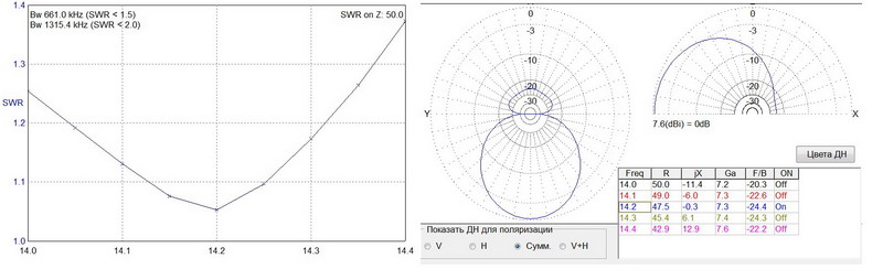
5 element Yagi at 14 MHz SAM 5-20. Design by RA3LE.
The Sov.Antenna team has embodied in hardware another successful development by Valery Ivanovich Tsygankov RA3LE. This is a highly efficient 5 element wave channel antenna for the 14 MHz range. The antenna has excellent parameters and is designed according to the principles of effective VHF antennas.
 |
  |
Range - 14 MHz
Number of elements - 5
Traverse length - 13.5 m
Turning radius - 8.5 m
Wind area - 1.1 sq.m.
Weight - 37 kg without taking into account the weight of the antenna mounting plate to the mast.
SWR (14.0 – 14.150 – 14.3) - 1.25 – 1.1 – 1.3
Antenna price - 28,000 rub.
The traverse extension is of the “double triangle” type.
Packaging - one box 3 x 0.25 x 0.25 m
5 Yagi elements at 28 MHz SAM 5-10. Design by RA3LE.
The new development of the talented radio amateur RA3LE has been implemented by our team. The antenna length is 7.5 m, powered by a 50 Ohm cable through a balun of any available design.
 |
 |
Traverse length - 7.55 m
Antenna weight - 15 kg
F/B ratio - up to 29 dB
Feeder - 1 coaxial 50 Ohm (powered through a 1:1 balun)
Antenna price - 15,500 rub.
The antenna has excellent broadband, does not need tuning and will bring pleasure from working on this wonderful range that has begun to “come to life”. It's time to prepare the antenna industry for new achievements!
SAD 1-40. Dipole range 40 m.
Rediscover the exciting 7 MHz range. With the SAD 1-40 antenna, you will get real pleasure from working with an excellent low-noise antenna, especially in industrial areas, where the low level of noise in horizontal polarization will allow you to experience the remarkable depth of the amateur radio broadcast, and communicate with correspondents whom you simply cannot hear on vertical antennas . The shortening of the length is carried out by high-quality inductance of a large diameter, which has a good effect on the efficiency and broadband of the antenna. The relatively small size and weight allow the antenna to be placed above an existing antenna system.

Length - 14.7 m
Weight - 11.5 kg
SWR (7.0 – 7.05 – 7.1) - 1.3 – 1.1 – 1.3 (SWR bandwidth 1.5 – 180 kHz)
Wind resistance - 0.31 sq.m
The antenna is powered by one 50 Ohm cable through a 1:1 balun of any design.
Antenna price 11,300 rub.
The price of an antenna with a double triangle element extension is 12,000 rubles.
Packaging - one box 1.6 x 0.25 x 0.2 m
SAY 2-40 Two-element wave channel with a range of 40 m.
A wonderful and high-quality antenna with a range of 40 m. With an output power of 60 W, during the “break-in” radio communications were carried out with radio amateurs on all continents. Great antenna!

Basic parameters of the SAY 2-40 antenna 2 Yagi elements at 40 m
Range 40m Gain (dBd) 3.6 Gain (dBi) 10.5 Forward/backward ratio (dB) 15 SWR 7,00 - 7,06 - 7,20 1,4 - 1,1 - 2,0 Number of elements 2 Max. length el. (m) 14.9 Boom length (m) 5.6 Turning radius (m) 7.96 Feeder 1 Coaxial 50 Ohm via 1:1 balun of any design Weight (kg) 30 Wind resistance at 130 km/h 500 N / 0.62 m² / 6.8 feet² Price 21,200 rub.
SAM 3-40L Three-element full-size antenna 40 m range


An excellent uncompromising broadband antenna with a 40 m wave channel will bring pleasure from working with rare correspondents. The traverse is made of D-16T, the elements are combined from AD 31T1 (thick pipes) and D16T (from 25 mm and thinner), which made it possible to make an antenna with excellent mechanical parameters. The antenna was made based on the calculations of Valery Ivanovich Tsygankov RA3LE.

Boom length - 11 m
Maximum length of el. - 22 m
Turning radius - 12.8 m
The antenna is powered by a 50 Ohm cable through a 1:1 balun of any design
Antenna price - 46,000 rub. SAY 3-40S - 45,000 rub.
SAY 2-30 Two-element wave channel with a range of 30 m.

Basic parameters of the SAY 2-30 antenna 2 Yagi elements at 30 m
Range 30m
Gain (dBd) 3.6
Gain (dBi) 10.5
Forward/backward ratio (dB) 20
SWR
10,10 - 10,12 - 10,15 1,3 - 1,1 - 1,3
Number of elements 2
Max. length el. (m) 9.3
Boom length (m) 3.6
Turning radius (m) 4.96
Feeder 1 Coaxial 50 Ohm fed through a 1:1 balun of any design
Weight (kg) 20
Wind resistance at 130 km/h 350 N / 0.44 m² / 4.8 feet²
Price 18800 rub.
Packaging - one box 3.1 x 0.2 x 0.2 m
SAM 3-20 3-element antenna for 20 m range


A beautiful and convenient antenna for comfortable operation in the 14 MHz range. Antenna comes with traverse with double-volume triangle type braces (RUB 13,000) and in the standard version.
Traverse length (m) 7.4
Maximum element length (m) 11.2
Input impedance (Ohm) 50
The antenna is fed via a 1:1 balun
Antenna weight (kg) 23
Antenna price 12,600 rub.
SAM 5-15 5-element antenna for 15 m range
A very successful development by V.I. Tsygankov. RA3LE. Broadband antenna 5 el. with high parameters for serious household work.
Traverse length - 8.5 m
Antenna weight - 17 kg
Gain - 7.76 dBd (9.91 dBi)
F/B ratio - up to 29 dB
Feeder - 1 coaxial 50 Ohm (powered through a 1:1 balun)
Antenna price - 15700 RUR .
Tel. +7-916-4161489 e-mail: This e-mail address is being protected from spambots. You need JavaScript enabled to view it.
In radio communications, antennas are given a central place; to ensure the best radio communications, antennas should be given the closest attention. In essence, it is the antenna that carries out the radio transmission process itself. Indeed, the transmitting antenna, powered by current high frequency from the transmitter, converts this current into radio waves and emits them in the desired direction. The receiving antenna carries out inverse conversion- radio waves into high-frequency current, and the radio receiver performs further transformations of the received signal.
At radio amateurs, where you always want more power, for communication with possibly more distant interesting correspondents, there is a maxim - the best amplifier (HF) is an antenna.
For now, I belong to this club of interests somewhat indirectly. There is no amateur radio call sign, but it’s interesting! You can’t work for the program, but you can listen and get an idea, that’s all. Actually, this activity is called radio surveillance. At the same time, it is quite possible to exchange with the radio amateur whom you heard on the air, receipt cards of the established form, in the slang of radio amateurs QSL. Many HF broadcasting stations also welcome confirmation of reception, sometimes encouraging such activity with small souvenirs with the logos of the radio station - it is important for them to know the conditions of reception of their radio broadcasts in different parts of the world.
An observer radio can be quite simple, at least at first. An antenna, a structure by far, is more bulky and expensive, and the lower the frequency, the more bulky and expensive it is - everything is tied to the wavelength.
The bulkiness of antenna structures is largely due to the fact that at low suspension heights, antennas, especially for low-frequency ranges - 160, 80.40 m, do not work well. So what makes them bulky is precisely the masts with guys, and the lengths are tens, sometimes hundreds of meters. In short, not particularly miniature things. It would be nice to have a separate field for them near the house. Well, it depends.
So, an asymmetrical dipole.

Above is a diagram of several options. The MMNA mentioned there is a program for modeling antennas.
The conditions on the ground turned out to be such that a two-part version of 55 and 29m fit comfortably. I stopped there.
A few words about the radiation pattern.
The antenna has 4 petals, “pressed” to the canvas. The higher the frequency, the more they “press” against the antenna. But truth and empowerment mean more. So on this principle
It is possible to build completely directional antennas, which, however, unlike the “correct” ones, do not have particularly high gain. So you need to place this antenna taking into account its radiation pattern.
The antenna on all bands indicated in the diagram has SWR (standing wave ratio, a very important parameter for an antenna) within reasonable limits for HF.
To match an asymmetrical dipole - also known as Windom - you need a SHPTDL (broadband transformer on long lines). Behind this terrible name lies a relatively simple design.

It looks something like this.

So what was done.
First of all, I decided on strategic issues.
I made sure that the basic materials were available, mainly, of course, suitable wire for the antenna fabric in the required quantity.
I decided on the location of the suspension and the “masts”. The recommended suspension height is 10m. My wooden mast, standing on the roof of the woodshed, was twisted in the spring by the frozen snow - it didn’t last long, what a pity, I had to remove it. It was decided for now to hook one side to the ridge of the roof; the height would be about 7m. Not enough, of course, but cheap and cheerful. It was convenient to hang the other side on the linden tree standing opposite the house. The height there was 13...14m.
What was used.
Tools.
Soldering iron, of course, with accessories. Power, watts, about forty. Tools for radio installation and small plumbing. Anything drilling. A powerful electric drill with a long drill bit for wood was very useful - pass the coaxial cable through the wall. Of course there is an extension cord for it. I used hot glue. There will be work at heights - it is worth taking care of suitable, strong ladders. It really helps to feel more confident, away from the ground, wearing a safety belt - like the ones that fitters have on poles. Climbing up, of course, is not very convenient, but you can work “there”, with both hands and without much fear.
Materials.
The most important thing is the material for the canvas. Used a “vole” - field telephone wire.
Coaxial cable to reduce as needed.
A few radio components, a capacitor and resistors according to the diagram. Two identical ferrite tubes from RF filters on the cables. Thimbles and fasteners for thin wire. A small block (roller) with an ear mount. A suitable plastic box for the transformer. Ceramic insulators for antenna. Nylon rope of suitable thickness.
What was done.
First of all, I measured (seven times) pieces of wires for the canvas. With some reserve. Cut it off (once).
I set about making a transformer in a box.
I selected ferrite tubes for the magnetic core. It is made of two identical ferrite tubes from filters on monitor cables. Nowadays old CRT monitors are simply thrown away and finding “tails” from them is not particularly difficult. You can ask around with your friends, probably someone else is collecting dust in their attics or garage. Good luck if you have friends system administrators. After all, in our time, when there are everywhere impulse blocks power supply and the fight for electromagnetic compatibility is serious, filters on cables can be found in many places, moreover, such ferrite products are vulgarly sold in electronic component stores.
Selected identical tubes are folded like binoculars and secured with several layers of adhesive tape. The winding is made of mounting wire of the maximum possible cross-section, such that the entire winding fits in the windows of the magnetic circuit. It didn’t work out the first time and I had to proceed by trial and error, fortunately there were very few turns. In my case, I didn’t have a suitable section at hand and had to wind two wires at the same time, making sure in the process that they did not overlap.
To obtain a secondary winding, we make two turns with two wires folded together, then pull each end of the secondary winding back (to the opposite side of the tube), we get three turns with a midpoint.

The central insulator is made from a piece of fairly thick PCB. There are special ceramic ones specifically for antennas; it is better, of course, to use them. Since all laminated plastics are porous and, as a result, very hygroscopic, so that the antenna parameters do not “float”, the insulator should be thoroughly impregnated with varnish. I used oil glyphthalic, yacht.

The ends of the wires are cleared of insulation, passed through the holes several times and thoroughly soldered with zinc chloride (Soldering Acid flux) so that the steel wires are also soldered. The soldering areas are washed very thoroughly with water to remove flux residues. It can be seen that the ends of the wires are pre-threaded into the holes of the box where the transformer will sit, otherwise you will then have to thread all 55 and 29 meters into the same holes.
I soldered the corresponding leads of the transformer to the cutting points, shortening these leads to a minimum. Don’t forget to try it on the box before each action so that everything fits.

From a piece of PCB from an old one printed circuit board, cut a circle into the bottom of the box, there are two rows of holes in it. Through these holes, a coaxial cable is attached using a bandage made of thick synthetic threads. The one in the photo is far from the best this application. This is a television with foam insulation of the central core, the core itself is “mono”, for screw-on TV connectors. But there was a cove of trophy available. I applied it. The circle and bandage are thoroughly varnished and dried. The end of the cable is pre-cut.

The remaining elements are soldered, the resistor is made up of four. Everything was filled with hot glue, probably in vain - it turned out a bit heavy.

Ready-made transformer in the house, with “conclusions”.

In the meantime, a fastening to the ridge was made - there are two boards at the very top. Long strips of roofing steel, 1.5mm stainless steel loop. The ends of the rings are welded. On the strips, along a row of six holes for self-tapping screws, distribute the load.

The block has been prepared.

I didn’t get ceramic antenna “nuts”, I used vulgar rollers from old wiring, fortunately, they are still found in old village houses for demolition. Three pieces on each edge - the better the antenna is isolated from the “ground”, the more weak signals can accept.
The field wire used has woven steel cores and can withstand stretching well. In addition, it is designed for laying outdoors, which is also quite suitable for our case. Radio amateurs quite often make wire antenna sheets from it, and the wire has proven itself well. Some experience has been accumulated in its specific application, which, first of all, says that you should not bend the wire too much - the insulation bursts in the cold, moisture gets on the wires and they begin to oxidize, in that place, after a while, the wire breaks.
It’s impossible to even imagine how many antennas are growing around us: mobile phone, TV, computer, wireless router, radios. There are even antenna devices for psychics. What is a HF antenna? Most non-radio people will answer that it is a long wire or a telescopic pole. The longer it is, the better the reception of radio waves. There is some truth in this, but it is very little. So what size should the antenna be?
Important! The dimensions of all antennas must be commensurate with the length of the radio wave. The minimum resonant length of the antenna is half the wavelength.
The word resonance means that such an antenna can operate effectively only in a narrow frequency band. Most antennas are resonant. There are also broadband antennas: You have to pay for a wide bandwidth in terms of efficiency, namely gain.
Why does the stereotype work that the longer the HF antennas, the more effective they are? In fact, this is true, but to certain limits, since this is typical only for medium and long waves. And as the frequency increases, the antenna sizes can be reduced. At short waves (lengths from approximately 160 to 10 m), antenna sizes can already be optimized for efficient operation.
Dipoles
The simplest and efficient antennas- These are half-wave vibrators, they are also called dipoles. They are powered in the center: a signal from the generator is supplied to the dipole gap. Amateur radio portable antennas can operate as both transmitters and receivers. True, transmitting antennas are distinguished by thick cables and large insulators - these features allow them to withstand the power of transmitters.

The most dangerous place for a dipole is its ends, where voltage antinodes are created. The maximum current of the dipole is in the middle. But this is not scary, because the current antinodes are grounded, thereby protecting receivers and transmitters from lightning discharges and static electricity.
Note! When working with powerful radio transmitters, you may receive shock from high-frequency currents. But the sensations will not be the same as from a blow from a socket. The blow will feel like a burn, without shaking in the muscles. This is due to the fact that the high-frequency current flows over the surface of the skin and does not penetrate deep into the body. That is, the antenna can burn the outside, but the inside will remain untouched.
Multiband antenna
Quite often it is necessary to install more than one antenna, but this is not possible. And in addition to a radio antenna for one band, antennas for other bands are also needed. The solution to the problem is to use a multi-band HF antenna.
Possessing fairly decent characteristics, multi-band vertical antennas can solve antenna problem for many shortwave operators. They are becoming very popular for a number of reasons: lack of space in cramped urban environments, the growth in the number of amateur radio bands, the so-called “bird license” life when renting an apartment.

Multi-band vertical antennas do not require much space for installation. Portable structures can be placed on the balcony or you can go with this antenna somewhere to a nearby park and work there in field conditions. The simplest HF antennas are a single wire with asymmetrical feeding.
Someone will say that a shortened antenna is not that. The wave loves its size, so the HF antenna must be large and efficient. We can agree with this, but most often there is no opportunity to purchase such a device.
Having studied the Internet and looked at the designs of finished products from different companies, you come to the conclusion: there are a lot of them, and they are very expensive. All these designs contain is a wire for HF antennas and one and a half meters of pin. Therefore, it will be interesting, especially for a beginner, to find a fast, simple and cheap option for homemade production of effective HF antennas.
Vertical Antenna (Ground Plane)
The Ground Plane is a vertical ham radio antenna with a long quarter wavelength pole. But why a quarter and not a half? Here the missing half of the dipole is mirror reflection vertical pin from the ground surface.
But since the earth conducts electricity very poorly, they use either sheets of metal or just a few wires spread out like a chamomile. Their length is also chosen equal to a quarter of the wavelength. This is the Ground Plane antenna, which means earthen platform.

Majority car antennas for radio receivers it is done according to the same principle. The wavelength of the VHF radio broadcast is about three meters. Accordingly, a quarter of a half-wave will be 75 cm. The second beam of the dipole is reflected in the car body. That is, such structures must, in principle, be mounted on a metal surface.
Antenna gain is the ratio of the field strength received from the antenna to the field strength at the same point, but received from the reference emitter. This ratio is expressed in decibels.
Magnetic loop antenna
In cases where simplest antenna cannot cope with the task, a vertical magnetic loop antenna can be used. It can be made from a duralumin hoop. If in horizontal loop antennas their technical performance is not affected by the geometric shape and method of power supply, then this does affect vertical antennas.

This antenna operates on three bands: ten, twelve and fifteen meters. It is rebuilt using a capacitor, which must be reliably protected from atmospheric moisture. Power is supplied by any 50-75 Ohm cable, because the matching device ensures the transformation of the transmitter output impedance into the antenna impedance.
Short dipole antenna
There are shortened 7 MHz antennas, the arms of which are only about three meters long. The antenna design includes:
- two shoulders about three meters;
- edge insulators;
- ropes for guy ropes;
- extension coil;
- small cord;
- central node.
The coil winding length is 85 millimeters and 140 turns wound closely. Accuracy isn't that important here. That is, if there are more turns, this can be compensated by the length of the antenna arm. You can also shorten the length of the winding, but this is more difficult; you will have to solder the ends of the fastening.
The length from the edge of the coil winding to the central unit is about 40 centimeters. In any case, after manufacturing, the antenna will have to be adjusted by selecting the length.
DIY vertical HF antenna
How to make it yourself? Take an unnecessary (or buy) inexpensive carbon fishing rod, 20-40-80. Glue a paper strip with dot markings onto it on one side. Insert clips into the marked places to connect jumpers and bypass the unnecessary coil. Thus, the antenna will switch from band to band. The shaded areas will contain the shortening coil and the indicated number of turns. A pin is inserted into the “fishing rod” itself.

You will also need materials:
- copper winding wire is used with a diameter of 0.75 mm;
- wire for counterweight with a diameter of 1.5 mm.
A whip antenna must work with a counterweight, otherwise it will not be effective. So, if you have all these materials, all that remains is to wind the wire bandage on the rod so that you first get a large reel, then smaller and even smaller. The process of switching antenna bands: from 80 m to 2 m.
Selecting the first HF transceiver
When choosing shortwave transceiver For a beginner radio amateur, first of all, you need to pay attention to how to buy it, so as not to make a mistake. What are the features here? There are unusual, highly specialized radios - this is not suitable for the first transceiver. There is no need to choose handheld radios designed for on-the-go operation with a whip antenna.
![]()
Such a radio station is not convenient for:
- use it as a conventional amateur radio device,
- start making connections;
- learn to navigate the amateur radio airwaves.
There are also radio stations that are programmed exclusively from a computer.
The simplest homemade antennas
For radio communications in the fields, it is sometimes necessary to communicate not only over distances of hundreds of kilometers, but also over short distances from small portable radio stations. Stable communication is not always possible even over short distances, since terrain and large buildings can interfere with signal propagation. In such cases, raising the antenna to a small height can help.
A height of even 5-6 meters can give a significant increase in the signal. And if audibility from the ground was very poor, then by raising the antenna a few meters the situation can improve significantly. Of course, by installing a ten-meter mast and a multi-element antenna, long-distance communications will definitely improve. But masts and antennas are not always available. In such cases it helps homemade antennas, raised to a height, for example, on a tree branch.
A few words about shortwaves
Shortwave operators are specialists with knowledge in the field of electrical engineering, radio engineering, and radio communications. In addition, they have the qualifications of a radio operator, are able to conduct radio communications even in conditions in which professional radio operators do not always agree to work, and, if necessary, are able to quickly find and fix a malfunction in their radio station.

The work of shortwave operators is based on shortwave amateurism - the establishment of two-way radio communications on short waves. The youngest representatives of shortwave frequencies are schoolchildren.
Mobile phone antennas
A dozen years ago, small beads stuck out of mobile phones. Today nothing like this is observed. Why? Since there were few base stations at that time, it was possible to increase the communication range only by increasing the efficiency of the antennas. In general, the presence of a full-size antenna mobile phone in those days it increased the range of its work.
Today when base stations stuck every hundred meters, there is no such need. Moreover, with the growth of generations mobile communications there is a tendency to increase frequency. HF mobile communication bands have expanded to 2500 MHz. This is already a wavelength of only 12 cm. And not a shortened antenna, but a multi-element one can be inserted into the antenna housing.
You can’t live without antennas in modern life. Their variety is so huge that I could talk about them for a very long time. For example, there are horn, parabolic, log-periodic, directional antennas.
Video
Antennas. antennas 2 antennas 3 antennas 4
Antenna LW
I consider it necessary to publish a description of the LW-82 m antenna (in common parlance - a rope). The fact is that this antenna, at minimal cost - no feeder, no need to go to the roof (it is enough to live on the 2nd floor and have a suspension point at a distance of more than 80 m from your house) has very good parameters and allows you to start working on the most interesting ranges 160, 80, 40 m.
A description of such an antenna is also in the book “HF-VHF Antennas” by the authors Benkovsky, Lipinsky, fig. 5-20. A very important note: the tuner for this antenna must have good radio grounding, and these are only quarter-wave counterweights for each band, in the worst case, the heating system of your home. The diagram of the simplest tuner for such an antenna is presented below:
Coil L1 is wound on a frame with a diameter of 40 mm with a wire with a diameter of 1-1.25 mm and contains 50 turns with a winding length of 70 mm. The coil has taps from the 13th turn (range 40 m), counting from the right, and from the 23rd turn, counting from the right (range 80 m); when taps are not used, the entire coil operates on the 160 m range. Naturally, to the right of the 13th turn, taps can be made for the ranges of 20, 15, 10 m. The taps are indicated approximately according to V.A. Suvorov (UA4NM). For your tuner, naturally, the turns will have to be selected individually according to the SWR meter turned on before the tuner or, in the simplest case, according to the maximum air noise on a given range or according to the neon light bulb for the transmission.
Vladimir Kazakov
Efficient balcony antenna at 145 MHz
I needed a universal antenna, with good characteristics for working in different conditions on 145 MHz, for example from home, when it is not possible to install an antenna on the roof, from a car, in a parking lot and, of course, while camping. After going through different designs, I settled on a two-element directional antenna. Despite the simplicity (I would even say banality) of the design, it has many advantages, and the ease of manufacture allows us to call it a “weekend design.”


In the photographs you can see how this antenna is installed on my balcony. The design turned out to be strong; it is not afraid of rain and strong winds. Before that, on the balcony, I had several different antennas: a zigzag without a reflector, the branded A-100 and A-200, but this particular design proved its effectiveness, so I removed the rest of the antennas as unnecessary. When installed on the roof, 2 el. at 145 MHz they do not play with a 3x5/8 collinear antenna, I tested the A-1000 5 meters long. When testing, at a distance of 50 km, the signal from the A-1000 and the 2-element antenna was the same. This is how it should be because the A-1000 has a real gain of approximately 4 dB, and the one described here is 2x el. antenna 4.8db. It always outperformed any car antennas of the following types: 1/4, 1/2, 5/8, 6/8, 2x5/8. If two such antennas are phased together, they confidently outperform the A-1000. Check it out for yourself and see for yourself.


Let's look at the design, it is very simple (although it may not be beautiful in appearance, I did it in 40 minutes) and consists of a reflector 1002 mm long and a split vibrator 972 mm long (10 mm cable gap). The distance between the reflector and the active element is approximately 204 - 210mm. The elements themselves are made of 4mm insulated wire. If your wire is different, you need to adjust the dimensions. Cover the soldering areas with damp rubber to prevent moisture from entering. SWR from 144 to 146 MHz, approximately 1.0 - 1.1, measurements were carried out with the SWR-121 device.

The antenna input impedance is 12.5 ohms, for optimal matching with the 50 ohm cable, I used a transformer made from two pieces of fifty-ohm cable. They should have the same length, 37 - 44 cm (choose more precisely when setting up) each. Both pieces of cable must be pressed against each other along their entire length. That's all. I recommend this antenna to everyone, instead of pins, zigzags, branded collinear antennas and other crap that clearly have too much gain! If you compare it with two squares, then with approximately equal gain, for two squares you will need 4 meters of wire, but for this antenna only two. For two squares, you will need a stronger stick because they will be noticeably heavier. The difference in gain is 0.3 dB, which is completely insignificant for real QSOs, but the suppression on the sides and back is 2. The antennas are much smaller and this is also a plus, because we need a circular radiation pattern.
High gain option

Many people ask how to further increase the gain of the described antenna and at the same time maintain a wide lobe. When adding elements, not only will the gain increase, but the petal will also narrow greatly. Everything is very simple, you need to phase several antennas of the same type. The picture shows how to do this. The easiest way is to phase 2 or 4 antennas; you only need to space them vertically, because horizontal separation will also narrow the main lobe. Since the described antenna has weak directivity, you will get an antenna with high gain and an almost circular pattern. Another important advantage of connecting several antennas of the same type is improving the quality of reception of mobile stations on the move. Yes, yes, to this one simple design mobile stations will be accepted much better than on various branded pins 5 - 7 meters long (type A-1000, 3x5/8, etc.). I also recommend installing such antennas in cities that are surrounded on all sides by mountains. Now the numerous “reflections” that appear in such places will work for you. In such conditions, 2 x 2 will actually outperform “solid” multi-element antennas. The actual gain of a two-antenna design is approximately 7.3 dB. But keep in mind that it will receive better than a single antenna with a real gain of 8-10 dB. Four phased antennas will have a gain of 12.3 dB, and the directivity will be almost circular! No single antenna can compete with it!
Hiking option

After some time, a collapsible version of the antenna was made for hiking and expeditions. Tests in the field have confirmed its good efficiency; it is not inferior to collinear antennas 3 - 5 meters long (2x5/8 or 3x5/8) at a range of up to 50 km and outperforms them at distances of 90 km or more. The photo shows the camping version of the antenna, disassembled. It takes 30 seconds to assemble the antenna. A plastic water pipe with a length of 510 mm and a diameter of 21 mm is used as a boom. The dimensions of the elements were slightly adjusted because a different wire was used. For such a small antenna, there will always be a place in your backpack, and at high altitudes, in the mountains, you won’t have to make excessive efforts to hold it (those who were at 4000 and above know what I’m talking about). The cable and transformer are located inside a plastic pipe, this protects them from accidental breaks and moisture. The antenna can be repaired right on the go; bent elements just need to be straightened by hand, etc.
50 ohm antenna option

At the request of the “lazy people” who did not want to make a transformer, I calculated an antenna with a resistance of 50 ohms for direct connection to the cable going to the radio station. Appearance remained the same. The cable is connected to the active element directly; to improve symmetry, I recommend making one turn around the ferrite ring, as close as possible to the soldering point. The gain of this antenna option is slightly less and is approximately 4.3 dbd. The dimensions are given for wire with a diameter of 4 mm; if you have a different material, you need to adjust the dimensions. The distance between the reflector and the active element must be selected more accurately, within the range of 415 - 440mm, until the minimum SWR is obtained.
Simple tri-band antenna
The antenna is operational in the ranges of 40, 20, and 10 meters. A transformer on a HF-50 ferrite ring with a cross section of 2.0 cm is used as a matching element. The number of turns of its primary winding is 15, the secondary winding is 30, the wire is PEV-2 with a diameter of 1 mm.

When using a different section, you must reselect the number of turns using the diagram shown in the figure.

As a result of the selection, it is necessary to obtain the minimum SWR in the range of 10 m. The antenna manufactured by the author has the SWR:
1.1 - on the 40 m range;
1.3 - on the 20 m range;
1.8 - on the 10 m range.
V.Kononovich (UY5VI). "Radio" No. 5/1971
20 meter indoor antenna


L1=L2=37 turns on a frame with a diameter of 25 mm and a length of 60 mm of wire with a diameter of 0.5 mm. J1 connector in a small plastic case.
Compact antenna tuner


The circuit works perfectly and matches the antenna from 80 to 10. Surprisingly, I didn’t find any losses in the tuner when testing at 50 Ohm load. Either bypassing 100 W, or through a tuned tuner 100 W, on all ranges from 80 to 10.... The coil, although compact, is cold... The resonance is quite sharp, and this tuner can be perfectly used as a preselector .
In general, everything works great with SW-2011, because... there is no DFT in it and the tuner plays the role of a preselector, which has a very beneficial effect on the quality of reception. I don’t recommend using “Amidon” rings, as many in the “West” do in these tuners - they are both expensive and overheat (introduce losses). Simply not sense. A regular reel on a plastic frame is much more
better. From experience - the diameter of the frame for power up to 100 W does not matter much - I checked from 50mm to 13mm in the last version. There is no difference. The main thing is to maintain the total inductance of the coil at about 6 μH, and proportionally recalculate the taps (or select them specifically for your antenna)
The critical components are KPIs. If the gap is small, it “stitches” them, because the voltage across them reaches hundreds of volts. But nevertheless, even with small-sized capacitors, I achieved normal operation (without breakdowns at 3.5 and 7 MHz as I had at first) by introducing the SW2 toggle switch, which switches the antenna output tap on the 3.5 and 7 MHz ranges to most of the turns coils. This achieves a reduction in the voltage on the capacitors when tuning the tuner.

Shortened vertical antenna

The vertical antenna described below, designed for operation on the 80 m band, has a total height of slightly more than 6 m.
The basis of the antenna design is pipe 2 with a diameter of 100 mm and a length of 6 m, made of dielectric (plastic). Inside the pipe, to give it mechanical strength, there is a wooden block 3 with spacers 4, which are in contact with the inner surface of the pipe. The antenna is installed on base 7.
Approximately 40 m of copper single-core wire 5 with a diameter of 2 mm, having moisture-resistant insulation, is wound onto the pipe. The winding pitch is selected so that the entire wire is evenly wound around the pipe. The upper end of the wire is soldered to a brass disk 1 with a diameter of 250 mm, and the lower end is connected through a variable capacitor 6 to the central core of the coaxial cable 8. This capacitor should have a maximum capacitance of about 150 pF and in terms of quality (rated voltage, etc.) not must yield to the capacitor used in the resonant circuit of the transmitter output stage.
Like any vertical antenna, this antenna requires a good grounding or counterweight 9. Tuning and matching the antenna with the feeder is done by changing the capacitance of the capacitor 6, and, if necessary, changing the length of the wire wound on the pipe.
The quality factor of such an antenna is higher and, therefore, its bandwidth is narrower than that of a conventional quarter-wave vibrator.
Built by a radio amateur WA0WHE a similar antenna with a counterweight of four wires has an SWR of up to 2 in a bandwidth of about 80...100 kHz. The antenna is powered via a coaxial cable with a characteristic impedance of 50 Ohms.
Ground Plane for 5 kV bands
The proposed antenna option can be classified as a “weekend design”, especially for those shortwave operators who already have a “GROUND PLANE” station for the 20-meter range at their station. As can be seen from the figure, in the center of the antenna there is a duralumin pipe with a diameter of 25...35 mm, which serves as a supporting mast and a vertical quarter-wave element for a range of 20 m.
At a distance of 402 cm from the base of the pipe, a fiberglass plate measuring 60x530x5 mm is fixed with two M4 screws. The ends of four-wire (3 mm in diameter) vertical elements are attached to it, the electrical length of which corresponds to a quarter of the wavelength for the middle of the 17, 15, 12 and 10 m ranges.
A fiberglass plate measuring 180x530x5 mm is screwed to the lower end of the pipe with two M4 screws. An aluminum plate measuring 15x300x2 mm with five holes with a diameter of 4.5 mm is placed under the lower edge of the pipe, through which five M4 screws are passed, which are used to fasten the wire elements and the pipe. To ensure better electrical contact, a piece of copper wire is inserted between the pipe mounting screws and any nearby wire element.

At a distance of 50 mm from the aluminum plate, another one of the same size is fixed, but with 6-12 holes, which are used for attaching radial counterweights (six for each range).
The antenna is fed via a coaxial cable with a characteristic impedance of 50 Ohms.
The dimensions of all elements and counterweights are indicated in the table. The distance between vertical elements is 100 mm. Due to the windage of the antenna, it is fixed with two tiers of nylon guys. The first tier is fixed at a distance of 2 m from the base of the pipe, the second - at a distance of 4.1 m.
If you have a “GROUND PLANE” on 40 m, then using the described principle you can create a 7-band antenna.
Indoor broadband...
Wideband indoor active loop antenna S. van Roogie increases the efficiency of receiving radio stations of all HF bands (3-30 MHz) by approximately 3-5 times compared to a telescopic one. Due to loop antennas sensitive to the magnetic component of the electromagnetic field, electrical interference created by various household appliances is significantly weakened.
Interference-resistant shortwave receiving antennas
(Review of materials from the magazine "QST", 1988)
Many fans of long-distance radio reception on short waves, as well as short-wave radio operators who are interested in conducting DX radio communications, especially in the low-frequency HF bands, and who have at their disposal only a GP antenna with vertical polarization, often face in practice the problem of ensuring noise-free radio reception. “Moreover, in the conditions of large industrial cities, it is most significant. Signals from DX radio stations are often quite small, while the field strength of industrial, atmospheric, etc. interference at the receiving point can be quite high. In this case, it is necessary to solve the following problems :
1 - weakening of this interference at the input of the radio control unit with the least attenuation of the useful signal;
2 - ensuring the possibility of receiving radio signals in the entire shortwave range, i.e. broadband antenna-feeder device;
3 - the problem of providing sufficient area to place the antenna away from sources of additional interference. Significant reduction in the level of atmospheric, industrial, etc. interference can be achieved by using special receiving antennas with low noise levels. In the literature they are called "Low-Noise Receiving antennas". Some types of such antennas have already been described in (1, 2, 3). This review summarizes some interesting experimental results in this area obtained by foreign radio amateurs.
EXPERIMENTAL SHORT-WAVE RECEIVING ANTENNAS WITH LOW NOISE LEVEL
When starting to engage in long-range radio reception on KB, you must first of all think about a good noise-proof antenna, this is the key to success. As already noted, the task of an anti-interference antenna device is to reduce interference to the greatest possible degree with the least possible attenuation of the useful signal. For obvious reasons, it is impossible to talk about the amplification of the useful signal by the receiving antenna, especially in the low-frequency HF bands, because such an antenna will take up quite a lot of space and have a pronounced directivity. In some cases, to amplify the received signal, it is advisable to use pre-amplifiers between the radio control unit and the antenna, providing them with manual gain control (1). This also applies to antennas, which will be discussed below. These antennas are a modification of the Beverage antenna, the classic version of which is shown in Fig. 1a. This antenna is widely used in professional HF radio communications and has some anti-interference properties. W 1FB experimented with a modification of the Beverage antenna and obtained interesting practical results, which he published in the April issue of QST magazine. Some shortwave operators considered them an April Fool's joke, while others, on the contrary, supplemented these results with their own practical experience. In Fig. 1b. shows an antenna with the exotic name "Snake" (which means "snake"). It consists of a long piece of coaxial cable placed on the ground or in the grass. The far end of the cable is loaded with a non-induction resistor with a resistance equal to the characteristic impedance of the cable. This resistor must be placed in an insulating box and sealed to prevent moisture from entering the coaxial cable.

Since making practically such an antenna for the low-frequency KB bands is quite expensive, due to the high price of the cable, W 1FB proposed making the antenna from a two-wire ribbon cable or wire for a telephone or radio broadcast line.
The characteristic impedance of such lines is different and can
be determined from tables, as well as experimentally. When determining the length of this antenna, it is necessary, as in the first case, to take into account the shortening factor. The antenna in the form of a two-wire loaded line for the 160-meter range should have a length of about 110 meters. It is quite difficult to place such an antenna above the ground, so W 1FB laid the cable around the perimeter of its site. In this case, the basic properties of the antenna are preserved if there are no foreign objects nearby that could affect the antenna’s performance and be a source of additional noise. This could be vertical antenna grounding systems, various metal pipes, fences, etc. When an antenna is placed around the perimeter of the site, its directional properties are weakened and it begins to receive signals from different directions. In this design, it is important to accurately determine the characteristic impedance of the two-wire line used. This is necessary for the correct calculation of the matching broadband transformer and load resistor, the resistance of which must be equal to the characteristic impedance of the line used. The transformation ratio is selected depending on the coaxial cable used. It is equal to:
R H /R K -(N/n) 2
Where: R H - load resistor resistance, Ohm;
R K - characteristic impedance of the coaxial cable, OM;
N is the number of turns of the transformer winding on the antenna side;
N is the number of turns on the receiver side (power line).
In Fig. 1 year the antenna proposed by W 1HXU is shown. It is located above the ground and is made of ribbon cable with a characteristic impedance of 300 Ohms. To configure it, a variable capacitor with a capacity of up to 1000 pF is used. The capacitor is adjusted to the highest level of the received signal. Figure 1 d shows an antenna of the “Snake” type, made of a coaxial cable having a length of just over 30 meters, which is laid in the ground. The far end of the cable has a connection between the central core and the braid. At the "receiving end" the braid is not connected to anything. This antenna was tested by W 1HXU and obtained good results on the 30, 40 and 80 m bands.

CONCLUSION
When making antennas with low level interference, it should be taken into account that they weaken the useful signal quite strongly, so the use of coaxial cable antennas is justified only in cases of very high levels
industrial interference at the receiving point. As already noted, in these cases
It is advisable to use additional amplifiers. Antennas made of a two-wire symmetrical line in a tape dielectric have less attenuation of the useful signal and give more reliable results. It should also be noted that the use of all antennas described above is possible only if there is
in the input control panel, designed for connecting antennas with a wave impedance of 50 or 75 Ohms. If there is no such input, then you need to use an additional communication coil, which can be wound on top of the coil of the RPU input circuit for the HF band on which you expect to use these antennas. The number of turns of the communication coil is from 1/5 to 1/3 of the number of turns of the HF band loop coil. The connection diagram for the additional coil is shown in Fig. 2.
Multi-band antenna with switchable radiation pattern
The problem of creating a sufficiently efficient multi-band antenna in limited space, requiring relatively low costs, worries many radio amateurs. I would like to offer another version of the “poor radio amateur” antenna that satisfies these requirements. It is a system of slopers with pattern switching, operating on the bands 3.5, 7, 14, 21, 28 MHz. It is based on the operating principle of the RA6AA and UA4PA antennas. In my version (Fig. 1), 5 beams go from the top of a 15-meter mast at an angle of about 30-40° to the ground, which simultaneously serve as the upper tier of guys. There may be more beams, but preferably at least 5. The total length of each beam is 21 m, about 80 cm is subtracted from it for the outlet to the relay box and about 15 cm for fastening the insulator in the lower part of the beam. Thus, the actual length of each beam is about 20 meters. The antenna is powered by a coaxial cable with a characteristic impedance of 75 Ohms, approximately 39.5 meters long. The cable length is critical - together with the length of the beams, it must be 1 wavelength on the 80 meter range. All rays in original condition connected to the cable braid. The choice of the required direction is made directly at the workplace, while the corresponding relay connects the beam of the selected direction to the central core of the cable. As with most directional antennas, the suppression of the side lobes is more pronounced than the suppression of the rear lobes, and averages 2-3 points, less often - 1 point. A comparison was made with the RB5QT log periodic antenna suspended at a height of about 9 m above the ground in an east-west direction. At 7 MHz, slopers won in these directions by 1-2 points.

Design. The mast is telescopic, from R-140, stands on the ground without additional grounding, without dielectric inserts. The beams are made from field telephone cable P-275 (2 wires of 8 steel and 7 copper conductors each), well soldered using acid. 75 ohm coaxial cable. It is possible to use a cable with any characteristic impedance, as well as an open two-wire line with a resistance of 300-600 Ohms. The relay is used type TKE52 with a supply voltage of about 27 V with parallel contacts, but others can be used, depending on the power of the transmitter. A separate four-wire cable is used to power the relay. This circuit (Fig. 2) allows you to power 6 relays; due to local conditions, I have 5. To switch voltages, P2K buttons with dependent fixation are used. The dimensions of the antenna and power line can be changed in any direction, using the formula L2 = (84.8-L1 )*K, where L1 is the length of one arm, L2 is the length of the supply line; K is the shortening coefficient (for a cable - 0.66, for a two-wire line - 0.98). If the resulting line length is not enough, you must substitute 127.2 in the formula instead of 84.8. For a shortened version, you can substitute 42.4 m into the formula, but in this case the antenna will only operate at frequencies above 7 MHz.

Setup. The antenna practically does not need adjustment, the main thing is to comply with the specified dimensions of the beams and cable. When carrying out measurements with an RF bridge, it turned out that the antenna resonates within the amateur bands, and its input impedance is within 30,400 Ohms (see table), so it is advisable to use a matching device. I used the UA4PA recommended parallel circuit with taps. In the 160 m range, this antenna does not work - the resonant frequency of 1750 kHz was chosen so that in other ranges the resonance would be within the range.
| FREQUENCY | Zin, Ohm |
| 1750 | 20 |
| 3510 | 270 |
| 3600 | 150 |
| 7020 | 360 |
| 7100 | 400 |
| 10110 | 50 |
| 14100 | 260 |
| 14250 | 200 |
| 14350 | 180 |
| 18000 | 50 |
| 18120 | 50 |
| 21150 | 190 |
| 21300 | 180 |
| 21450 | 160 |
| 24940 | 59 |
| 25150 | 50 |
| 28050 | 160 |
| 28200 | 200 |
| 28500 | 130 |
| 29000 | 65 |
| 29600 | 30 |


