Some users believe that investing in LED lighting is an absolutely unnecessary luxury, which still does not carry any practical value. Other users, on the contrary, cannot live without an LED “disco” in the system unit of their home PC. For them, we have selected several of the best sets of LED strips that will allow you to organize a “party” in your computer case.
Lighting the inside of a PC is nothing new and has never been seen before. Light tubes and LED coolers have been used to decorate cases for decades. And now even motherboards are equipped with special controllers for connecting additional LED strips. You no longer need to play Kulibin if you want to add some “spark” to your corps.
Best Basic LED Kit
At a price of 1,200 rubles, it is one of the most affordable multi-color lighting kits. It includes two LED strips, 30 cm long and with 18 diodes each. This decision more suitable for use in Midi-Tower cases, which allow one tape on the top and one tape on the bottom inside the case. The tapes are attached with magnets, which is very convenient, and the plug is connected to the corresponding connector on the motherboard.
 To control the backlight, a wireless remote control is used, which allows you to control the backlight. Note that only the entire strip can be illuminated, and not each LED individually. This way, each LED on the strip will glow the same color at the same time. The remote control allows you to control the brightness and set the speed of changing shades on the LED strip, creating a “breathing” effect, for example. You can choose 15 colors for static lighting or RGB lighting mode.
Price: about 1200 rubles
Best Digital LED Light Kit

Unlike the previous set, the kit has ten LEDs on each strip, and each of them can glow in an individual color. In total, you will receive 40 LEDs, to which you can purchase 4 more strips with the same 40 diodes. In addition, the set comes with a huge number of different cables for connecting both the strips themselves and the fans (they are also included in the set).
The backlight on the controller itself, which is shaped like a small box, is not adjustable. If you don't like it, you can simply turn it off. The NZXT Hue+ controller is two-channel, which allows you to supplement the lighting system with 4 more strips (4 for each channel). In addition, this allows you to run two different lighting effects on each channel.
All control occurs through proprietary software, which already has eight preset modes work, but it doesn’t stop you from creating your own. For example, smart lighting modes allow the NZXT Hue+ to automatically change colors based on CPU or GPU temperature. Audio mode activates an equalizer-style glow: the light will respond to any sound coming from the PC.
Installation of the kit is quite simple. The controller is screwed in place of the 2.5-inch drive in the HDD cage. A four-pin plug for power and a data cable from the motherboard to the controller are connected from it to the motherboard.
Price: about 5000 rubles
The Best LED Lighting Kit for Customization Lovers


There are many pixel addressable LED strips on the backlighting market today, but they are the most convenient and effective solution when it comes to backlighting a gaming PC case. This huge 500cm long LED strip reel contains 300 LEDs, allowing you to cut LED strips to fit your housing. But, in addition to the LED coil itself, you will have to purchase a power supply and controller separately.
On sale you can find ready-made controllers with hundreds of programmed types of glow, and this will become the most simple option for purchase. More advanced users can use Arduino or Raspberry Pi boards to program their own lighting effects. In our case, we decided to limit ourselves ready-made solution With remote control. We did not cut the tape, but simply laid it along the inside of the PC case.
Those who decide to cut out individual LED strips will have to do further independent soldering to connect the strips. We recommend using 3-pin JST connectors so you can easily disconnect the strips without having to cut and re-solder.
Price: about 1600 rubles
Good day, dear readers. As you understand from the title, we will talk about connecting the front panel and motherboard connectors to the case or vice versa.
This is an article that is a small addition to the previously written material about assembling a computer under the same name “Building a computer with your own hands” or “What is what in a computer, part 2”.
We will talk about a small missing, but important element - connecting the connectors (all sorts of buttons, light bulbs, etc.) of the front panel.
Go.
Connecting the front panel - connection instructions
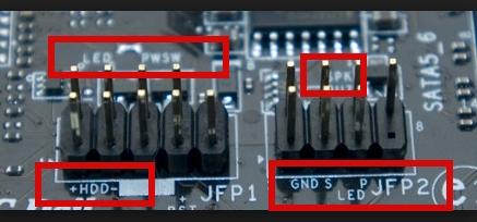
On the front panel system unit Usually there are power buttons and manual reboot buttons. They also need to be connected correctly to . Connection cables are usually made in the form of pins (see what pins are above).
They look something like this (clickable):

Power SW - power button cable; Power LED + - - power indicator (light bulb) cables; HDD LED – loading indicator cable (the same light that usually blinks); RESET SW - reset button cable.
Proper connection of the front panel is also important, because without this the computer simply will not turn on.
Each motherboard has a so-called Front panel contact block, or F-Panel for short. Usually it is located in the lower right corner of the board, but there are exceptions. This is roughly what it looks like:

Connection The connection of the front panel and its pins is carried out manually and for this purpose in accompanying documents There are definitely hints for the motherboard.

If you have the documents, then connecting the pins is not difficult. If not, there are clues on the motherboard itself around or near the F-Panel block. If you are lucky many times, then the motherboard comes with the following adapter:

Into which you simply plug in, as shown above, the connectors themselves, and then this adapter into the motherboard, and everything turns out quickly and simply. But not everyone is so lucky, and you probably got here because you are trying to connect everything for an existing (and not new) motherboard.
What else is worth knowing
In addition, on the front panel of the system unit there are sometimes USB interface connectors (usually a couple of them) and ports for connecting headphones/speakers and a microphone. It looks something like this:

The cable pins for connecting these external USB ports inside the system unit look like this:

They are connected to blocks of pins on the motherboard, which are called F-USB1 and F-USB2, respectively (they may not look exactly the same in color and location as in the screenshot below, but in shape and number/location of pins everything is the same):

The ports for connecting external devices look approximately the same. audio inputs, - the only difference is the position/number of pins, so connecting the front panel in this regard is not entirely a difficult task.
They are easy to connect (they simply won’t fit into other pin blocks). But there are also hints for them in the accompanying documents for the motherboard:

Actually, everything and nothing complicated about it.
What to do if there is no documentation for the motherboard?
Or take a magnifying glass and carefully examine the connection connector mentioned above on the computer motherboard:
Usually it is at least somehow, but symbolically signed, since from the second or third you can guess what is what and connect everything correctly. The wires are connected, as a rule, with the inscription on themselves:

Occasionally, the second row (far) faces the inscriptions in the other direction, but this is quite rare. One way or another, as I wrote above, not the first time, but the second time - you’ll guess :)
If you can’t see anything (whether your eyesight is weak or the inscriptions are poorly written), then open the website of the motherboard manufacturer and there you look for the “Support” section (or something like that), where you can usually download the instructions from the motherboard, where it is always described connection.

If you couldn’t find it on the manufacturer’s website, then you can find it on the Internet by searching for “board name” + the word manual. If you have minimal knowledge of English, you’ll definitely find a place to download it, and then you can open it, look at it, and connect it.
Afterword
If you have any questions or additions, write in the comments or using . I will be glad to help and just listen to you.
PS: The images shown are for example and informational purposes only. No advertising.
PS2: The article was written by a person who lives online under the nickname (friend and project assistant). For which I thank him very much.
In this article we will look at backlighting the computer system unit as one of the most common types of modding.
In the first part of our article, we will look at installing backlighting in various parts of the system unit. In the second part we will look at options for connecting the backlight.
1. External lighting.
This type of backlight allows you to see all the main external components of the computer in the evening.
1.1. Illumination of the front part of the system unit with LEDs
Diodes used in this paragraph
To begin with, we solder the LEDs to the extreme ends in series, and also solder 2 additional wires of 30 cm each to them.
We select the location of the LEDs and mark it with dots.
In our case, this is the place next to the DVDRom, where all the inputs are located. Therefore, I had to remove the DVDRom, as well as the protective shell.
.jpg)
We drill holes. We insert a chain of LEDs into these holes

1.2.External lighting of the lower part of the system unit.
This type of lighting requires the presence of legs on your system unit, so it is suitable for experienced modders.
For this it is best to use LED strip

The tape is easily cut with ordinary scissors into pieces that are multiples of 5 cm. The pieces are easily connected to each other with wires. In this article we will cut the tape into several pieces for clarity, but you can use 4 pieces around the perimeter of the system unit.


We attach our structure to the body using a self-adhesive layer of tape and connect


The tape from this section was used. full range with all kinds of colors.
2. Illumination of the inside of the system unit
This can be done in several ways.
2. 1. Using LEDs().
We solder the LEDs in series. We solder the long leg (+) of the first LED to the short leg (-) of the other LED.

We solder the wires to the remaining two free legs.

We place the LEDs in the system unit. It is best to place them on the bottom and back wall.

2. Using pieces of LED strips.
Having LED clusters, you do not have to solder each diode separately.

LED clusters are connected to each other by two wires 5 cm long, so they can be placed either closely or at some distance. They are inserted into the holder and placed around the perimeter of the inside of the system unit using double sided tape.

Clusters must be placed so that they do not interfere with the installation of expansion cards, disk drives and other mods. If there are not enough wires between the clusters, you can extend them yourself.
.jpg)
After installing the clusters in place, all that remains is to connect the power.

Clusters can be quite expensive and in most cases there is no point in using them. You can take it and cut it into 5 cm pieces. In the end you will get the same thing, only for a smaller amount.
3. Illumination using LED strip.
The installation principle is similar to the installation of LED clusters, but significantly. The tape has 2 terminals on each side for connecting wires, and is also equipped with a self-adhesive surface, thanks to which you can install the backlight without the use of additional devices. Before fixing the tape, it is better to degrease the surface. 
4. Cooler lighting
This is the only type of backlight where we will use wires powered by the cooler itself as an energy source in order to do without unnecessary wiring.
To begin with, we take 2 LEDs and solder them according to the standard circuit.

We glue the LEDs on the inside of the cooler. We take food directly next to the cooler.


Now you just need to connect the cooler and the LEDs will work simultaneously with it.

Connecting the backlight.
1. To 4-pin molex connector
The 4-pin molex is the most common power connector in a computer. This connector contains four contacts: +12 V (most often the yellow wire), +5 V (red wire), as well as two ground contacts (black). When connecting the backlight to a 4-pin molex, you can choose where exactly to connect the LEDs, to 12 or 5 volts. 
In our case, you need to connect to a 12 volt source.

Before connecting, you must first check the correspondence of the selected contacts with a multimeter and determine the polarity. After this, you need to solder a 120 ohm resistor to the positive contact, from which, in turn, we draw another wire and connect it to the “plus” of our backlight. The “minus” is soldered to the ground contact of the molex connector. After this, carefully insulate the wires and cover them with heat shrink tubing.

For example, let's connect a single LED.


2. To 3-pin connector
The 3-pin connector is a standard connector for connecting fans in a computer, and similar connectors are most often superfluous. Therefore, it is reasonable to use them to connect the backlight. The 3-pin connector has 3 pins: +12 V, ground, and a third pin, which is used by the fan speed sensor.

The connection principle is identical to connecting to a 4-pin connector. We also use a 12 volt pin and a ground pin. However, it is important to remember that 3-pin connectors are intended for connecting fans and. Therefore, they cannot withstand the load of a 4-pin connector. But it is still suitable for connecting LED backlighting. Also, here we need a resistor with a resistance of 220 ohms. Otherwise there are no differences. We carry out the same operations as in the first case.


3. To the USB connector.
USB is a data connector and is generally used for this purpose, however, in addition to data, the USB connector also transmits voltage and can be used for power different devices. The USB connector has four contacts: two of them are responsible for data transfer and two more are responsible for voltage transfer. The USB connector has a 5 V voltage source with a current of up to 500 mA. There are 2 USB type connectors: 4 x 12 mm and 7 x 8 mm.

The differences between them are only in form. To connect the backlight there is no difference between them. In our example, the first version of the USB connector is used.

This type of connector requires an 82 ohm resistor. As in the first two cases, we determine the polarity and solder a resistor to the “plus”. “Minus” is also attached to the “ground” contact. We close all connections with heat shrink tubing.
.jpg)

Can be connected to a computer.

There is also an elegant solution - using flexible neon! In this case, a neon cord of different colors is pulled along the cables and connected to the inverter.
Having problems with desktop computer there may be various reasons. By following our advice, you can quickly fix any problem.
PC failure can manifest itself in different ways. For example, after pressing the power button, the machine shows no signs of “life”. Or the computer turns on, but some components do not function. The first step is to figure out what actually works and what doesn’t. Are the motherboard LEDs on? Are the fans spinning? Is the monitor receiving an image signal? Are BIOS messages displayed? Based on these observations, most problems can be classified into six categories (see below). For each category, we provide instructions consisting of sequential steps with which you can eliminate the possibility of simple faults, so that you can then proceed to more complex diagnostics. If you are not successful at any step, move on to the next one until you solve the problem. Even if you stop at some step, the results of your testing will subsequently become a good help for the service center employees.
1. No signs of life
If the computer does not respond in any way when you press the power button, you should first check the power supply or the button itself. We will help you localize the problem.
1.1. VISUAL INSPECTION. First of all, check if the power cord is well connected and turned on. network filter. It is possible that the power supply button on the back of the computer is in the “Off” position.
1.2. CASE CONNECTORS. Open the PC case and check that the connectors are securely connected and that the cable is not damaged in the area between the switches and LEDs of the case and motherboard- perhaps some connector has come loose from the plug. If one or more cables are disconnected, open your motherboard manual and check to see if the cables are properly connected to the plugs.
1.3. POWER BUTTON. If the case connectors are connected correctly or reconnecting them does not bring results, disconnect all connectors from the motherboard. Then close the two contacts labeled " Power Switch» using a paper clip. If the computer turns on, there are two options. The first is a faulty power button on the case. In this case, you need to connect both connectors labeled “Reset Switch” to the contacts labeled “Power Switch” on the motherboard. From this moment on, the PC will be turned on using the reset button, and the power button will no longer perform its function. Another reason for such a malfunction may be a short circuit in the reset button: a regular button in this case will not work, and starting the PC will only be possible by shorting two contacts on the motherboard. This assumption will be confirmed by the ability to start a PC with the reset button disabled. In this case, leave the power button connected and disconnect the reset button. After all these steps, your PC will most likely turn on again without any problems. If even when using an office paper clip the computer refuses to “start”, then you should check the power system.
1.4. MOTHERBOARD POWER SUPPLY. Check that all power supply connectors are correctly connected to the motherboard. We are talking not only about a wide ATX connector with 24 pins, but also an additional four-pin P4 connector for powering the processor.
1.5. POWER UNIT. Next, you need to exclude the possibility of failure of the power supply. To do this, connect a working power supply to the PC - for example, from a second computer. Connect the 24-pin ATX connector and the four- or eight-pin P4 connector of the working computer to the motherboard of the faulty PC and try to start it. If after this it turns on, then the whole problem is in the power supply, which will need to be replaced.
1.6. MOTHERBOARD. If all the measures described above did not help, then most likely the motherboard, which is best replaced, since repairs not under warranty, as a rule, are not worth it. One way or another, replacing the motherboard means complete disassembly and assembling your PC. But it is recommended to proceed with this procedure only if other possible malfunctions have been excluded.
2. PC works, but no image
After turning on, the screen remains black, although the power supply, CPU and video card fans are running and the LEDs on the motherboard are lit.
2.1. CHECKING THE MONITOR. The first thing you need to do is rule out a trivial malfunction by answering the question: does the monitor turn on? If not, there may be a power problem: the cable is unplugged from the display or wall outlet, or the screen has a switch that is set to the Off position. If the monitor turns on, open the OSD menu and check if the input source (VGA/D-Sub, DVI, HDMI) is selected correctly.
2.2. SOUND AND LIGHT SIGNALS. If the monitor is not receiving an image signal, the motherboard will often let you know by sending beeps or lights to help you figure out what the problem is. Consult your motherboard manual to determine what the signals mean. One of the typical defects reported in this manner may be faulty or incorrect installed modules RAM, which the motherboard, depending on the model, warns about with sound signal or burning LED lamps.
2.3. RESET BUTTON. A short circuit in the reset button may also be the cause of these symptoms. Perform the check (point 1.3).
2.4. BIOS. Sometimes the cause of such startup problems can be incorrect BIOS settings. To reset BIOS settings, find the Clear CMOS jumper on the motherboard. We are talking about three contacts, two of which are connected by a jumper. Remember initial position jumper, then pull it out and connect another pair of contacts with it, wait at least ten seconds. After this, set it back to its original position. If the system board has a reset button, press it. If the computer turns on, check the BIOS settings. In most cases, you need to select the correct operating mode of the SATA controller, which, starting with Windows XP, is “AHCI” and not “IDE”. After this, the problem should disappear. One of possible reasons If the BIOS settings are lost, the motherboard battery may be dead - this will be discussed in paragraph 3.1.
2.5. RAM. Most motherboards indicate faulty memory using sound or light (LED) signals (see paragraph 2.2). However, we recommend checking the functionality of the modules random access memory without waiting for a warning signal. There must be at least two modules installed in the computer - remove one and try to boot the computer with it. If the PC does not turn on with this module, try starting the system with another module installed. If the computer starts with only one memory module, this usually means that the other one is faulty.
2.6. VIDEO CARD. Among PC components, the problem should first of all be looked for in the source of the image signal - the graphics card. If your computer has an integrated graphics card, remove the discrete card and test the system with the integrated GPU. Otherwise, check if the PC works with a different graphics card. If yes, then your discrete or integrated video card is faulty.
2.7. CPU. A faulty processor can also be the reason why the computer works but does not produce an image signal. Therefore, if possible, test the performance of your PC with another compatible processor before the next very difficult step.
2.8. MOTHERBOARD. Since all other possible sources of problems have now been ruled out, the last “suspect” remains the motherboard. The problem here could be, for example, in the CMOS chip in which the BIOS is stored, or in the PCIe bus to which the video cards are connected. Troubleshooting in most cases does not pay off, so the best solution will immediately replace the motherboard.
3. BIOS stops working
The BIOS's job is to prepare the computer to boot operating system. If in progress BIOS operation When problems arise, error messages will usually appear that will help you localize them.
3.1. BIOS SETTINGS. With computers released four or five years ago, situations often occur when they suddenly refuse to boot. The reason lies in the BIOS settings. In this case, the message “Please enter Setup to recover BIOS setting | CMOS Date/Time Not Set." You can usually enter the BIOS using the “F1” or “Del” button when you turn on the PC. After this, you need to restore all the basic settings - for example, the date, the sequence of boot devices, or such an important parameter as the operating mode of the SATA controller (AHCI). After restoring the settings, there should be no problems booting the PC. However, the reason that the settings were lost most likely lies in the following: there is a round flat-plate battery on the motherboard, which is an “emergency” power source for the CMOS chip so that the latter does not lose the settings. If this battery is discharged, it must be replaced, otherwise the BIOS settings will be lost every time the PC is turned off.
3.2. BOOT DEVICE SEQUENCE. If the BIOS reports that it cannot find bootable media, then there may be several reasons. First, check the boot device sequence in the settings. In modern motherboards To do this, you need to perform two operations. In the download options you will find the option " Boot priority"("Boot Device Priority"), which lists components such as hard disks, removable media or optical drives. HDD must have the highest boot priority.
3.3. DISK FAILURE. If the drive does not appear in the media selection menu in the BIOS, open the PC and check that the power cables and interface cables of the corresponding media are securely connected. If the problem is not resolved, test the drive with a different cable, in a USB HDD enclosure, or in another computer. If this does not help, then most likely the media has failed as a result of damage to the controller. In this case, most likely only a specialist will be able to recover the data at a considerable cost. If you regularly create system images and backups data, then you will only need to replace the disk and copy the data. Otherwise, you will have to completely reinstall the system.
3.4. LOAD SECTOR. If the boot device appears in the BIOS and you can view its contents when connected to another PC, then the boot sector is most likely damaged. This quite often happens when an attempt to reallocate disk space fails or when Linux is uninstalled as a second operating system. To resolve the error, boot from the installation DVD or disc disaster recovery. During the boot process, select “Repair your computer” or “PC recovery options”, then click on “System Restore”, and then follow the wizard’s instructions. If this does not solve the problem, then try restoring manually. Boot your PC again as described above, and in the system recovery settings, open the window command line. Enter the following commands in it:
bootrec /fixmbr bootrec /fixboot
bcdedit ;/export C:\bcd_1 c: cd boot attrib bcd -s -h -r ren bcd bcd_2 bootrec /RebuildBcd
After this, Windows should boot. If you still have difficulties, follow the instructions below.
4. OS cannot boot (Windows logo appears, but system does not start)
Your computer starts to boot, but freezes just before the user interface appears. With such symptoms, you can rule out many problems with the hardware and BIOS.
(to be continued)


