In this article, we suggest taking a look at another more budget-friendly option, designed for lovers of overclocking and performance systems with modern processors - the MSI P35 NEO motherboard.
Note that when a FireWire controller is installed on this board, the index F is added to the model name, and its name looks like MSI P35 NEO-F.
Specification of mother MSI boards P35 NEO:
|
Manufacturer |
|
|
North Bridge |
|
|
South Bridge |
|
|
CPU socket |
|
|
Supported processors |
Intel Core 2 Quad-Core / Core 2 Duo / Pentium / Celeron Intel Yorkfield, Wolfdale |
|
System bus, MHz |
1333/1066/800 MHz |
|
Memory used |
DDR2 800/667 MHz |
|
Memory support |
4 x 1.8 V DDR2 DIMM dual channel architecture up to 8GB |
|
Expansion slots |
1 x PCI-E x16 |
|
Disk subsystem |
Southbridge ICH9 supports: Additional controller Marvell 88SE6111 supports: |
|
Sound subsystem |
Realtek ALC888 8-channel audio codec |
|
LAN support |
Network controller RTL 8111B (10/100/1000 Mbit) |
|
24-pin ATX power connector |
|
|
Cooling |
Aluminum radiators on the north and south bridge |
|
Fan connectors |
1 x CPU |
|
External I/O ports |
2 x PS/2 ports for connecting keyboard and mouse |
|
Internal I/O ports |
8 x USB |
|
Overclocking capabilities |
Frequency change: FSB, PCI-Express, memory. |
|
Equipment |
1 x SATA cable |
|
Form factor Dimensions, mm |
ATX |
|
Products webpage |
The new BIOS version for MSI P35 NEO2-FR/FIR can be downloaded from the official page. |

The MSI P35 NEO motherboard is packaged in a small cardboard box designed in the MSI style. The packaging notes the presence of support for a 1333 MHz system bus and 45 nm processors.

MSI P35 NEO motherboard package includes:
- two CDs with drivers for Windows Vista and Windows XP;
- user manual and installation instructions,
- cable UltraDMA 133/100/66;
- Serial ATA cable;
- I/O panel blank;
- SATA power adapter.
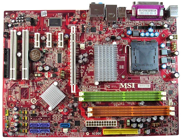
MSI P35 NEO motherboards have a fairly good layout - power connectors and ports are located mainly along the edge of the PCB. Although there are some drawbacks - in a not very favorable position, under the PCI slots, there is an FDD connector, as well as opening the latches of the green slots random access memory the inserted video card will interfere. When upgrading a computer, many users may want to have three PCI slots instead of the existing two, so we will also note this fact as a small drawback of the MSI P35 NEO. I was also not pleased with the lack of currently quite “fashionable” polymer capacitors. It is worth noting that on a similar PCB, MSI releases the MSI P35 Neo Combo, which supports both types of DDR2 and DDR3 memory, and the MSI G33 Neo with integrated graphics.

To cool the northbridge, a relatively large but not very tall aluminum radiator is used. The cooler on the south bridge is much smaller.

Since several sets of logic can be used to fill the PCB of the MSI P35 NEO motherboard, empty spaces are visible on it for two more SATA connectors, which are installed when using the Intel ICH9R south bridge, and there is also a place reserved for the FireWire controller. In our case, the MSI P35 NEO uses an Intel ICH9 chip, which supports four SATA II ports without the ability to create RAID arrays. To ensure the operation of the IDE port and another SATA port, an additional Marvell 88SE6111 controller is used.
For ease of connection, the eight internal USB ports and the system panel connector are color-coded.

The MSI P35 NEO motherboard only has two PCI slots, three PCIE x1 and one PCIE x16 slot. Among the controllers integrated on the board, we can note a gigabit network card based on RTL 8111B, eight-channel audio Realtek codec ALC888, the front panel connector of which supports connections in HDA and AC`97 formats.

The processor power regulator on the MSI P35 NEO motherboard is only three-channel, but for a board of this class this fact is not surprising.

The rear panel has the following ports: two PS/2 for keyboard and mouse, four USB connectors, COM and LPT ports, an RJ45 connector for network connections and connectors for 8-channel audio.
The MSI P35 NEO motherboard has three fan headers, one of which is 4-pin for the CPU cooler, and the rest, intended for connecting case fans, are 3-pin. All connectors are located in different parts of the board, which simplifies the choice of connection location.
The MSI P35 NEO motherboard uses an AMI code BIOS with a lot of settings. Almost all settings related to overclocking are located in a separate section of the Cell Menu.
Settings required for overclocking:
|
Parameter |
Menu name |
Range |
|
|
Processor technologies |
EIST, CPUID MaxVal, Execute Bit |
||
|
Proprietary intelligent overclocking technology |
1, 3, 5, 7, 10, 15 % |
||
|
CPU multiplier |
Adjust CPU Ratio |
||
|
System bus frequency |
Adjust CPU FSB Frequency |
||
|
Bus frequency PCI Express |
Adjust PCI-E Frequency |
||
|
Memory dividers |
FSB/Memory Frequency |
1:1.25; 1:1.5; 1:1.67; 1:1.2; 1:1; 1:1.2; 1:1.6; |
|
|
Memory timings |
CAS, RAS to CAS, RAS Precharge, RAS Act to Prechar, tRFC, tWR, TWTR, TRRD, tRTP |
||
|
CPU voltage |
|||
|
Memory module voltage |
|||
|
FSB bus voltage |
|||
|
Northbridge voltage |
1.25 – 1.65 V |
||
|
I/O controller voltage |
|||
|
Southbridge voltage |

In the BIOS it is possible to activate the proprietary automatic overclocking technology D.O.T. (Dynamic Overclocking Technology), with which you can overclock the processor from 1% to 15%.

To set the memory frequency, there are seven dividers that can be used to optimally set the frequency during overclocking.

As usual, it is possible to configure RAM timings and sub-timings, but you will notice the absence of the 1T/2T Memory Timing setting, which changes the command decoding time.

Wide ranges of voltage settings will improve system stability during overclocking. In addition, the levels of critical values are very conveniently shown, which will help less experienced users navigate.

In the Hardware Monitor window you can monitor:
- temperature of the processor and motherboard;
- rotation speed of the processor cooler and two case fans;
- voltage on the power lines 3.3V, 5V, 12V, 5V SB and the processor core.
In the “CPU Smart FAN Target” item, you can enable the function of automatically controlling the rotation speed of the processor cooler.

The MSI P35 NEO motherboard was able to run at a system bus frequency of 530 MHz. Considering the large range of settings in the BIOS, we can assume very good possibilities for overclocking processors with its help.

Testing the audio path based on the Realtek ALC888 codec
Overall results (RightMark Audio Analyzer)
Performance testing
The following equipment was used to test the capabilities of motherboards.
|
CPU |
Intel Core 2 Duo E6300 (LGA775, 1.86 GHz, L2 2 MB) |
|
Thermaltake Sonic Tower (CL-P0071) + Akasa AK-183-L2B 120 mm |
|
|
RAM |
2x DDR2-800 1024 MB PQI PC6400 |
|
Video card |
EVGA GeForce 8600GTS 256 MB DDR3 PCI-E |
|
HDD |
Samsung HD080HJ, 80 GB, SATA-300 |
|
Optical drive |
ASUS DRW-1814BLT SATA |
|
power unit |
Chieftec CFT-500-A12S 500W, 120 mm fan |
|
CODEGEN M603 MidiTower, 2x 120 mm in/out fans |


MSI P35 NEO shows an excellent level of performance for a board in its class.
conclusions
The MSI P35 NEO motherboard is a relatively inexpensive solution with good functionality and good overclocking potential, which, in a sense, managed to exceed our expectations. Although overclocking enthusiasts should take into account the far from the most powerful processor power regulator. The cost of the MSI P35 NEO is one of the lowest among offerings based on the Intel P35 chipset, and it has almost no obvious disadvantages. Perhaps some future owners would like to see more PCI slots, instead of the same PCI-E x1.
Advantages:
- support Intel processors Penryn, made using 45 nm technology;
- a large number of BIOS settings required for overclocking;
- tested bus capability at 530 MHz;
- 8-channel High Definition Audio;
- low cost for its class.
Flaws:
- lack of official support for DDR2-1066;
- very modest equipment;
- only two PCI slots;
- no external S/PDIF;
- There is no FireWire controller.
We would like to express our gratitude to PF Service LLC (Dnepropetrovsk) for the motherboards provided for testing.
Article read 30439 times
| Subscribe to our channels | |||||
|
|
|
||||
MSI P35 Diamond motherboard is a top-end model for Intel platform P35, which not only contains the latest hardware, but also has overclocking potential. Everyone knows that BIOS is the soul motherboard, which determines its functionality and performance.
Below is the BIOS setup menu for the P35 Diamond motherboard. All performance related features except peripheral devices, system time, power management, are located in the "Cell Menu" section. Those who want to adjust the frequency of the processor, memory or other devices (for example, graphics card bus and South Bridge) can use this menu.

Attention: Overclocking performance depends on environmental conditions, so we cannot guarantee that the following settings will work on every motherboard.
Remember, if you are not familiar with BIOS setup, it is recommended to use the "Load Optimized Defaults" option to quickly complete the setup and ensure proper system operation. Before overclocking, we recommend that users first boot the system with "Load Optimized Defaults" and only then perform fine tuning.

Cell Menu section of the P35 Diamond motherboard
All settings related to overclocking are located in the "Cell Menu" section. These include:
D.O.T. control (dynamic overclocking technology control)
Intel EIST (Enhanced Intel SpeedStep® Technology)
Adjust CPU FSB Frequency
CPU Ratio CMOS Setting (setting the processor frequency multiplier)
Advanced DRAM Configuration ( special settings dynamic memory)
FSB/Memory Ratio (ratio of FSB and memory frequencies)
PCIEx4 Speed Controller (PCIEx4 speed control)
Adjust PCIE Frequency (PCIE bus frequency)
Auto Disable DIMM/PCI Frequency (automatically disable DIMM/PCI clock frequency)
CPU Voltage (CPU supply voltage)
Memory Voltage
VTT FSB Voltage (VTT FSB supply voltage)
NB Voltage (North Bridge supply voltage)
SB I/O Power (South Bridge input/output power)
SB Core Power (South Bridge Core Power)
Spread Spectrum (clock frequency spectrum limitation)
The user interface of the "Cell Menu" section is very simple and groups similar functions; Users can match similar functions and make settings step by step.
Before overclocking, set the "D.O.T. Control" and "Intel EIST" functions to Disabled (enabled by default). These features must be disabled to allow custom processor and system bus voltages to be set. After completing these settings, the "CPU Ratio CMOS Setting" option will appear.


Adjust CPU FSB Frequency:
After loading the optimized settings, this function will automatically detect and display the CPU frequency. For example, for an Intel Core 2 Duo E6850 processor, the value "333 (MHz)" will be shown here. Frequency setting can be done using the number keys or the "Page Up" and "Page Down" keys. During the adjustment process, the value shown in gray "Adjusted CPU Frequency" will change according to the set frequency.

CPU Ratio CMOS Setting (setting the processor frequency multiplier):
Depending on the nominal frequency of the processor used, for example, 1333MHz, 1066MHz and 800MHz, the range of multipliers will be different. Usually the frequency is reduced to a minimum, which increases stability and ensures successful overclocking.

Advanced DRAM Configuration (special DRAM settings):
This item is intended to configure delays in the memory operating cycle. The lower the corresponding value, the higher the speed. However, the limit depends on the quality of the memory modules used.
Advice:
If you are using conventional overclockable memory modules available on the market, we recommend that you select Cell Menu > Advanced DRAM Configuration > Configure DRAM Timing by SPD and set the latter to Disable. . Next, 9 additional items will appear that will enable users to achieve better memory performance.

FSB/Memory Ratio (ratio of FSB and memory frequencies):
This setting determines the relationship between FSB and memory frequencies. If it is set to "Auto", the memory frequency will be equal to the processor FSB frequency. If it is specified by the user, follow the rule 1:1.25. For example, a 1333MHz processor with DDR2-800 memory, then 1333MHz / 4 x 1.25 x 2 = 833MHz. The DDR2 memory frequency will be 833MHz.

Advice:
Meeting the wishes of overclocking enthusiasts, MSI has created a special “Power User mode” in the “Cell Menu” ( custom mode food). Just press "F4" and it will show hidden menu. The "Power User mode" menu items are focused on memory settings and include the SCOMP and ODT values.


Adjust PCIE Frequency:
Typically, PCI Express bus speed does not have a direct relationship with overclocking; however, fine-tuning it will also help with overclocking. (The default setting is 100, it is not recommended to increase it beyond 120 as it may damage the graphics card.)
CPU Voltage (CPU supply voltage):
This point is critical for overclocking, however, due to the complexity of the relationships, finding best setting not easy. We recommend that users adjust this value with caution because incorrect installation may damage the processor. According to our experience, if you have a good fan, there is no need to set the CPU voltage limit. For example, for the Intel Core 2 Duo E6850 processor, it is recommended to set the voltage in the range of 1.45~1.5V.
Advice:
The P35 Diamond motherboard uses DDR3 memory modules. According to the JEDEC definition of DDR3, its frequency range is between 800 and 1600 MHz. The standard values are 800, 1066, 1333 and 1600MHz. Therefore, when installing some special DDR3 modules, we recommend that you set the minimum FSB/memory frequency ratio, and fine-tune the memory supply voltage to achieve success.
VTT FSB Voltage:
To provide similar supply voltages to all main devices, the VTT FSB voltage must also be increased. The increase should not be large so as not to cause a negative effect.
NB Voltage (North Bridge supply voltage):
The Northbridge plays a decisive role in overclocking, as it is important for maintaining the stability of the processor, memory and graphics card. This is achieved by increasing its supply voltage. We recommend that users fine-tune this setting.
SB I/O Power (South Bridge input/output power):
The South Bridge manages the connection of peripheral devices and expansion cards, which have recently played an increasingly important role on the Intel platform. The ICH9R's standard supply voltage is 1.5V, which determines the voltage setting for I/O devices. We recommend increasing the voltage to 1.7~1.8V, which will increase the stability of the joint operation of the North and South Bridges, and also help overclocking.
SB Core Power (South Bridge Core Power):
Previously, the South Bridge was ignored during overclocking, but with increasing supply voltage it increases performance.
In addition, remember that MSI in the supply voltage settings highlights their different values in different colors: gray corresponds to the standard value, white means a safe value, and a dangerous value is highlighted in red.

Adviсe:
MSI warns you to check fan speed and temperature frequently. Good cooling plays a decisive role during acceleration.

Attention:
The P35 Diamond is a powerful motherboard that provides a full range of overclocking features and system protection. If overclocking fails three times in a row, the system will automatically reset to default BIOS settings to reliably boot the system. Before overclocking, make sure that each component is able to withstand its mode. MSI Company is not responsible for any damage resulting from unsuccessful overclocking. This article is for informational purposes only.
Once all parameters have been set, we recommend saving them using the "User Settings" function in BIOS menu, which makes it easier to load settings, and also allows you to set standard settings if overclocking fails. The user can save two sets of settings and select the required one.
In the User Settings section, "Press Enter" to save the BIOS settings.

If overclocking fails, users still have the option to enter the User Setting section to set more appropriate parameters to restore normal operation.

How to overclock P35 Diamond motherboard
Earlier than expected, the Intel platform entered the era of DDR3 memory. DDR3 memory has lower operating voltage, heat dissipation and higher clock speed. It has better overclocking efficiency than DDR2. However, the chipset and memory modules still do not have an overclocking environment, and this limits the potential of DDR3.
The MSI P35 Diamond motherboard from MSI comes with DDR3 memory and looks very similar to the P35 Platinum. It has greater potential than its predecessor. The P35 Diamond motherboard can support Intel 1333MHz multi-core processors and use 1066MHz DDR3 memory modules for outstanding performance ().
When overclocked, the P35 Diamond has the same excellent overclocking performance as the P35 Platinum, but with some differences. Thanks to DDR3 memory, users have the ability to fine-tune certain components, such as supply voltage and frequency ratio, which will affect overclocking results. Finally, we'll take a closer look at the subtleties that you should keep in mind when starting overclocking.
Adviсe:
Overclocking increases the voltage of the main devices, and they generate more heat than usual. Therefore, cooling becomes an important issue during overclocking.
Attention:
OC is software environment, which any computer user comes into contact with every day. The stability of the OS determines the performance of the system. We recommend that users set the default settings during OS installation and do not enable any overclocking or optimization features.
Together with system board P35 Diamond we used an Intel Core 2 Duo E6850 processor. Memory modules provided by Corsair CM3X1024-1066C7 DDR3-1066, Nvidia GeForce 8600GTS graphics card, hard drive Western Digital WD740ADFD.
Memory modules Corsair CM3X1024-1066C7 DDR3-1066/7-7-7-21/1024MB/1.5V

DDR3 memory has lower operating voltage, heat generation and higher clock speed, which provides better efficiency acceleration When installing memory modules, setting the supply voltage is important.
Standard BIOS setting:

Window view of the program for determining system parameters (CPU-Z 1.40):


The next step is to enter the "Cell Menu" section in the BIOS. Next we set the frequency to 450MHz, frequency multiplier 8, which guarantees stability. According to the P35 chipset specification, as the CPU frequency increases, the memory frequency also changes. Therefore, to achieve stability, we change the FSB/memory frequency ratio to 1:1.

The following image shows the operating parameters we measured (depending on the surrounding conditions)

After completing the settings, you can press "F10" to save the settings and click "OK" to restart the system with the new settings.


Typically overclocking focuses on increasing the processor frequency, which reduces stability but remains a widely used technique. Below is the performance improvement achieved by overclocking.


According to the results, the performance improvement is about 5% and the system is very stable. Of course, users can determine the settings for their environment through step-by-step selection.
Every year a significant event occurs - Intel updates its chipset lines. While release dates for server and mobile chipsets may vary, June is traditionally chosen for desktop chipsets. Five generations of chipsets were released for the Pentium 4 from 2000 to 2005, and the current 965/975 line has been used in tandem with Core 2 processors for almost a year. On June 5, during the Comptex exhibition in Taipei (Taiwan), Intel will introduce a new line of 3x chipsets. In our article we will look at the new line of 3x chipsets, codenamed Bearlake.
Over the past few years, the importance of chipsets for PCs has changed significantly. In the days of the Pentium or Pentium II, the chipset had a huge impact on overall performance. But today this is no longer the case, because the second level cache (L2) has moved from motherboards (slow option) to processor boards (Slot A for Athlon, Slot 1 for Pentium II/III - a faster option), and then to the chip processor (Athlon for Socket 462 and Pentium III for Socket 370 - the most quick option). The integration of the L2 cache on the chip turned out to be very effective way increasing system performance.
Of course, the chipset is still an important part of the computer, as it contains all the important interfaces and largely determines the set of functions of the system. Improved technological processes not only made it possible to create the upcoming 45nm and modern 65nm processors, but also affected chipsets that could accommodate a larger number of transistors. Therefore, the level of integration has increased significantly. For example, all modern chipsets contain multiple interfaces for expansion cards (PCI Express or PCI), a dual-channel memory controller (on the Intel platform), several USB 2.0 controllers (two ports per controller), an HD Audio controller, gigabit network controllers and modern storage controllers Serial ATA with four to six ports. Some chipsets also contain controllers remote control. Today on a full-fledged motherboard for mass market has everything an average user needs. Except for the powerful graphics system, Certainly.
It is quite clear that in terms of feature set, the new 3x chipset came out on top. First, Intel will introduce the mass-market version of the P35, as well as the G33, also for the mass market, but with an integrated GMA 3100 graphics core. The faster G35 chipset and an enthusiast variant, the X38 (PCI Express 2.0), will appear in the third quarter. The P35 and G33 include not only DDR2 but also DDR3 memory controller. Both chipsets contain an updated Serial ATA controller with support for six devices and eSATA. But the most important feature, in our opinion, will be the official support for the FSB1333 bus frequency, which is required for the next generation Core 2 processor on the 45 nm process technology (Penryn).
History of Intel chipsets
Quite a few Intel chipsets have been released in recent years. We decided to summarize the data in the following table, reflecting the most important stages in the development of chipsets with separate graphics, starting with the first SDRAM chipsets for the Pentium 4 (2001).
| Chipset | Intel 845 | Intel 865/875 | Intel 915/925 | Intel 945/955/975 | Intel 965 |
| release date | 2001 | 2003 | 2004 | 2005 | 2006 |
| Code name | Brookdale | Springdale/Canterwood | Grantsdale/ Alderwood | Lakeport/Glenwood | Broadwater |
| Review on THG | Review | Review | Review Review |
Review | |
| Socket | 478 | 478 | LGA775 | LGA775 | LGA775 |
| Processor support | Pentium 4, Celeron | Pentium 4, Celeron | Pentium 4, Celeron | Pentium 4, Pentium D, Celeron D | Core 2, Pentium 4, Pentium D, Celeron D |
| Processor generation | 130nm Northwood | 130nm Northwood, 90nm Prescott | 90nm Prescott | 90nm Prescott, Smithfield | 90nm Prescott, Smithfield, 65nm Conroe |
| FSB frequency | FSB400, FSB533 | FSB533, FSB800 | FSB533, FSB800 | FSB533, FSB800, FSB1066 | FSB533, FSB800, FSB1066 |
| Memory controller | PC133 SDRAM, DDR266 | Dual DDR333, DDR400 | Dual DDR400, DDR2-533 | Dual DDR2-667 | Dual DDR2-800 |
| GUI | AGP 4X | AGP 8X | PCI Express x16 | PCI Express x16 | PCI Express x16 |
| Max. Memory | 2 GB | 4 GB | 4 GB | 8 GB | 8 GB |
| South Bridge | ICH2 (82801BA), ICH4 (82801DB) - 421 contacts | ICH5 (82801EB) - 460 pins | ICH6 (82801FB) - 652 pins | ICH7 (82801GB) - 652 pins | ICH8 (82801HB) - 652 pins |
| Number of USB ports | 4x USB / 6x USB 2.0 | 8x USB 2.0 | 8x USB 2.0 | 8x USB 2.0 | 8x USB 2.0 |
| UltraATA/100 | 2 channels | 2 channels | 2 channels | 1 channel | |
| RAID support | No | RAID 0 | RAID 0, 1 (ICH6-R) | RAID 0, 1.5 (ICH6-7) | RAID 0, 1.5 (ICH8-R) |
| Serial ATA | No | 2x Serial ATA/150 | 4x Serial ATA/150 | 4x Serial ATA/300 | 6x Serial ATA/300 |
| Sound | AC97 2.1 | AC97 2.3 | HD Audio | HD Audio | HD Audio |
| Net | Via PCI | Via CSA or PCI interface | Via PCI Express | Via PCI Express | Built-in 1 Gbit/s |
| Model options | 845D (DDR memory), 845G/GL (with graphics), 845G, GE, PE, GV (DDR333) | 865G (with graphics), 865PE (FSB800), 848P (single memory channel), 865GV (with graphics only) | 915G (with graphics), 915PL (max 2GB DDR400), 915GL (max DDR400 with graphics), 915GV (graphics only), 910GL (FSB533 and graphics only), 925XE (FSB1066) | 945G (with graphics), 945PL (max FSB800), 945GL (max FSB800 with graphics), 945GZ (max FSB800 and graphics only) | G965 (with graphics), Q965 (with graphics, control) |
The first 845 chipset (Brookdale) was introduced at a time when Intel was still hoping for PC800 Rambus DRAM (RDRAM). Back then, high-end computers used the i850 chipset (Tehama), which supported two RDRAM memory channels. PC800 memory at 400 MHz provided 3.2 GB/s of bandwidth, but was expensive and did not provide the massive performance boost everyone was hoping for. The first 845 chipset used PC133 SDRAM and was the first to support Pentium processors 4 for Socket 478 rather than Socket 423. Intel quickly released the 845D, which supported DDR-266 RAM, providing better performance, as a result of which this chipset was able to replace the 850E.
At the time, Intel was fighting against AMD Athlon, which performed well. Pentium 4 processors could not surpass the Athlon XP line until the advent of the 865 and 875 chipsets (Springdale, Canterwood) and faster models (3 GHz and higher), released in 2003. These platforms supported dual-channel DDR-400 memory for the first time, and the FSB increased the frequency from 133 to 200 MHz (FSB800 thanks to quadruple data transfer), resulting in our best choice for many months, even after the introduction of the first generation of PCI Express chipsets, namely , 915 and 925 (Grantsdale and Alderwood), which were released in mid-2004. The 9xx line of chipsets replaced the aging AGP 8X interface with the modern point-to-point serial PCI Express interface that is still used today. With the 915 and 925 chipsets, Intel also introduced DDR2 memory, which at DDR2-533 speeds did not provide higher performance, and the ICH6 southbridge provided four additional PCI Express lanes for expansion cards, a High Definition Audio controller and four Serial ATA/150 ports with flexible RAID support. Finally, in the 9xx line, the interface between the south and north bridge (266 MB/s) was replaced by a Direct Media Interface based on PCI Express, providing a speed of 1 GB/s (today 2 GB/s).
The chipsets that came out after the 915 and 925 didn't have any revolutionary features, but they were still better than the previous models. The 925XE was the first chipset to support the FSB1066 bus (physical frequency 266 MHz), which was required for the first Pentium 4 Extreme Edition processors. The 945 and 955 (Lakeport and Glenwood) increased the DDR2 memory frequency to 333 MHz (DDR2-667), and the ICH7 added two more PCI Express lanes (six instead of four), and the SATA controller was updated to Serial ATA/300. RAID support now includes RAID 5, but Intel has abandoned the two legacy UltraATA/100 interfaces. Dual-core Pentium D processors required a 945 or 955 chipset.
ICH8 became the current south bridge for the 965 (Broadwater) chipset line, which, together with the 975X, became the foundation for the promotion of Intel Core 2 processors. The 965 chipset lost the UltraATA controller, and the AC97 interface was removed in favor of HD Audio solutions, which today can be called a standard . The ICH8 supports SATA 2.5, including external SATA (eSATA) ports, and contains a Gigabit Ethernet controller. The basic ICH8 model supports four SATA ports, but the ICH8-R RAID version supports six.
Each generation of chipsets has a number of models that use the integrated graphics core, using part of the RAM for the frame buffer. This allows PC builders to offer inexpensive machines for office and multimedia needs, but the integrated graphics are still not enough to run modern 3D applications or games. The 915G and 910G chipsets use the GMA900 graphics core with four pixel pipelines operating at 300 MHz, and support MPEG2 and DirectX 9 hardware decoding. However, the performance is still not enough for modern games. The 945G chipset had an updated graphics core, the GMA950 frequency increased to 400 MHz, but it still did not receive full support for Shader Model 3 (DirectX 9.0c). But the GMA950 at least supports HD video. Finally, the 965 line has a GMA3000 graphics core, with eight programmable pipelines, which runs at 667 MHz when running video or graphics calculations.

The new line of chipsets consists of four variants: G33, G35, P35 and X38. The G33 and P35 chipsets will be released on June 5, and two more versions will appear in early autumn. All chipsets still use Intel socket Land Grid Array with 775 pins (LGA775). Therefore, they can theoretically work with all existing Socket processors 775: Pentium 4, Celeron, Celeron D, Pentium D and Core 2 Duo/Quad. Although we've heard that Intel is removing support for NetBurst processors, meaning pre-Core 2 processors won't run on most 3x motherboards, some boards will still be able to run Pentium 4 processors.
"Intel does not validate any 3x line chipsets for processors that are not part of the Intel Core micro-architecture. If ODM plans to provide such support, it will not be covered by Intel's warranty and quality."
In general, if this feature is important to you, check the information on the manufacturer’s website before purchasing.
The G33 and G35 contain GMA X3100 and X3500 graphics cores, which are compatible with DirectX 10, but still not suitable for gamers. As before, the latest Intel graphics cores usually provide all the necessary functions for processing video and playing more or less decent 3D graphics, but they are noticeably inferior in performance to separate video cards. At least the G33 and G35 chipsets support hardware playback of HD video from HD DVD or Blue-Ray, which Intel implements in the form of Clear Video Technology. P35 is a chipset for the mass market, designed to install one video card. There will also be a version of the Q35 with a graphics core from the G33, but aimed at the corporate sector (with vPro support). The X38 chipset is aimed at enthusiasts and will support DDR3-1333 memory (which, by the way, will not be on the market at the launch of the P35 and G33). In addition, this is the first chipset for Socket 775 that supports PCI Express 2.0 (we’ll talk about DDR3 memory a little later). PCI Express uses the same connectors and is backward compatible with PCI Express 1, but throughput per line doubled (500 MB/s versus 250 MB/s).
All new 3x chipsets are manufactured using a 90nm process technology, which is a first for chipsets. This technical process not only reduces power consumption, but also makes it possible to passively cool PCI Express 2.0 chipsets, the power consumption of which increases with the increase in the number of PCI Express lanes. The P35 northbridge consists of 45 million transistors (this is more than 42 million in the first Pentium 4 Willamette) and has a thermal package (TDP) of 14.5 W (P965 and 975X required up to 19 W). However, the X38 chipset will probably work with a thermal package close to 20 W. You can also expect greater overclocking capabilities from it, since Intel has already announced that it will remove many overclocking protections.
Even if support for FSB1333 and DDR3 does not interest you (especially since DDR3 has little impact on performance yet), pay attention to the new ICH9 southbridge. If the south bridges ICH6, ICH7 and ICH8 were packaged in a BGA package with 652 contacts, then ICH9 is packaged in a 676-pin Ball Grid Array package, and the south bridge contains 4.6 million transistors and is manufactured using a 130 nm process technology. Although there are more transistors than in ICH8, the thermal package is still 4 W. The ICH9 provides six full-featured Serial ATA/300 ports with NCQ (Native Command Queuing), and also supports eSATA and port multipliers that allow up to four devices to be connected to a single SATA port. We found that the USB 2.0 and RAID performance of the ICH9 south bridge is superior to the ICH8 and ICH7, but we'll talk more about that in the benchmarks section.

45nm processors require VRM 11
One of the reasons for supporting a different generation of processors is the voltage regulator on 3x motherboards. It should be compatible with VRM 11.0, which is required for 45nm processors. And the problem is not the voltage levels, but the severe voltage fluctuations due to millions of transistors turning on/off. Or simply due to the switching on/off of sections of the crystal. It should be remembered that future quad-core processors will be able to dynamically adjust the clock speed of each core individually, as well as turn on/off cores depending on the load.
Thus, if a motherboard with a 965 chipset supports VRM 11, it will technically be possible to install 45nm processors on it. VRM 11 programs the power lines using 8-bit voltage IDs (VIDs), which give a step size of 0.00625 V. The minimum operating voltage is no longer 0.8375 V (as in the VRM 10 specification), it has been reduced to 0.5 V VRM 11 also splits the load across more phases, and the lines support so-called dual edge modulation, which allows regulators to apply multiple pulses to transistors using capacitors smaller capacity. The goal is not only to reduce voltage steps and lower operating voltage for 45nm processors, but also to ensure sufficient power at different voltage levels, which can change frequently. All this is carried out together with a more stringent specification of the voltage slew level.
Overclocking: good start on FSB1900
We didn't have much time to test overclocking, but we can safely say that upcoming motherboards (as well as chipset versions) will feature improved overclocking capabilities. As we mentioned above, the P35 chipset is great for overclocking. On the MSI P35 Platinum motherboard we were able to get FSB 1900 without special effort. We are confident that many motherboards will be able to surpass the FSB2000 level.
| FSB overclocking | 1100 | 1150 | 1200 | 1250 | 1300 | 1350 | 1400 | 1450 | 1500 | 1550 |
| nVidia 680i | x | x | x | x | x | x | x | x | x | x |
| Intel 975X | x | x | x | x | x | x | x | x | x | x |
| Intel 965P | x | x | x | x | x | x | x | x | x | x |
| AMD 580X | x | x | x | x | x | x | x | x | x | x |
| nVidia 650i | x | x | x | x | x | x | x | x | x | x |
| Intel P35 | x | x | x | x | x | x | x | x | x | x |
| FSB overclocking | 1600 | 1650 | 1700 | 1750 | 1800 | 1850 | 1900 | 1950 | 2000 |
| nVidia 680i | x | x | x | x | x | x | |||
| Intel 975X | x | ||||||||
| Intel 965P | x | x | x | x | x | x | x | x | |
| AMD 580X | x | x | x | x | x | x | x | ||
| nVidia 650i | |||||||||
| Intel P35 | x | x | x | x | x | x | x |
Speeding up: DDR3 memory
DDR3 memory still uses dual data transfer technology, where bits are transferred on both the rise and fall of the signal, allowing for double the effective bandwidth. However, the memory has so-called prefetch buffers, which are used to collect data in order to transfer it to the interface faster. DDR1 has a 2-bit buffer width (DDR mode, no buffering), DDR2 works with 4-bit buffers, and DDR3 works with 8-bit buffers. This is a way to increase memory performance, but latencies also increase: DDR1 memory operates with CAS latencies of 2, 2.5 and 3 clock cycles. DDR2 operates with CL latencies of 3, 4 or 5 clock cycles. For DDR3, CL delays increased to 5-8 clock cycles. That is, it takes time to fill the buffers. For this reason, you shouldn't expect DDR3 memory to outperform DDR2 right from the start. DDR2-533 memory on CL 3 also could not outperform DDR1-400 in real applications X.
Each generation of DDR is characterized by higher memory latencies, which is due to the increase in capacity with the transition to the next technological process. Mass DDR1 memory had a capacity of 512 MB per module (total capacity 1 GB). For DDR2, the optimal capacity was 1 GB per module (total capacity 2 GB). As one can assume, DDR3 memory will provide 2 GB per module (4 GB total) by mid-2008. According to JEDEC specifications, DDR3 memory must operate at a default voltage of 1.5 V. Recall that DDR2 memory voltage is 1.8 V, and DDR1 is 2.5 V. However, many memory manufacturers increase the voltage to reduce latency and provide more high performance. History with DDR3 memory is repeating itself.
Due to lower voltage, DDR3 memory consumes less power. But we couldn't confirm this in our tests, since test systems with DDR3 memory consumed more power than with DDR2 memory. Intel claims that the power consumption of DDR3-1333 memory should be equal to DDR2-800, and at equal clock speeds the savings should be 25%. Well, let's see how these promises come true in the future.

Two tables show the main technical data of DDR3 memory. We have already mentioned operation at lower voltage and with increased capacity (there will be no DDR3 modules with a capacity of less than 512 MB). The memory chips turned out to be slightly larger, the number of contacts has increased, but this is unlikely to have a significant impact on the modules.

Source: Microsoft and Micron
DDR3 frequencies
The following table lists all DDR3 frequencies that will be available until 2008.
| Memory | Standard | Memory frequency | Memory bus frequency | Effective frequency | Bandwidth per channel | Bandwidth of two channels |
| DDR2-667 | PC2-5300 | 166 MHz | 333 MHz | 667 MHz | 5.3 GB/s | 10.6 GB/s |
| DDR2-800 | PC2-6400 | 200 MHz | 400 MHz | 800 MHz | 6.4 GB/s | 12.8 GB/s |
| DDR3-800 | PC3-6400 | 100 MHz | 400 MHz | 800 MHz | 6.4 GB/s | 12.8 GB/s |
| DDR3-1066 | PC3-8500 | 133 MHz | 533 MHz | 1066 MHz | 8.5 GB/s | 17.0 GB/s |
| DDR3-1333 | PC3-10600 | 166 MHz | 667 MHz | 1333 MHz | 10.6 GB/s | 21.2 GB/s |
| DDR3-1600 | PC3-12800 | 200 MHz | 800 MHz | 1600 MHz | 12.8 GB/s | 25.6 GB/s |
Intel suggests that DDR3 memory will be scalable to DDR3-2133, giving the PC3-17000 a 266 MHz clock and 1066 MHz I/O bus. It remains to be seen whether there will be a niche for products aimed at enthusiasts at that time.
We have collected the results of DDR2 and DDR3 memory tests at popular frequencies and latencies. As you can see, DDR3 memory requires a significant increase in clock frequency in order to bypass DDR2 memory. We believe AMD will not move to DDR3 memory until it reaches at least DDR3-1333. On the other hand, DDR3 will not become widespread until mid-2008, and the integrated memory controller of Athlon 64 X2 processors (and the Phenom line) is more sensitive to latency than the Intel memory controller. Intel has the advantage of a more advanced caching architecture, which equalizes the performance of different types of memory.


The number of pins of DDR2 and DDR3 memory modules is identical, but the cutout for DDR3 modules has been shifted, since the new memory is incompatible with DDR2 and operates on a different voltage. DDR3 will be supported at frequencies of 800, 1066 and 1333, while DDR2 will stop at DDR2-800. Of course, DDR2 modules with more high frequency may work with some chipsets (this often depends on the combination of modules and motherboard), but the specifications are unlikely to ever be approved. In principle, the situation is quite normal if we remember that DDR memory for enthusiasts was available up to DDR600 frequencies, although JEDEC certified a maximum of DDR400.

Although the number of contacts has not changed, the cutout has been moved. Therefore, DDR2 and DDR3 modules are not compatible.

Corsair was the first company to send DDR3 memory to our laboratory. The first modules operate in DDR3-1066 mode with average latencies. We are confident that memory for enthusiasts will also appear on the market in the coming months. Corsair is almost ready to send us DDR3 memory for DDR3-1333 frequencies, although it will be many months before such memory can be called affordable for the average buyer.


New Core 2 processors for FSB1333: E6x50
Several new processors will be released for FSB1333.
| Core 2 Extreme X6850 | 3.0 GHz | Four cores | FSB1333 |
| Core 2 Duo E6850 | 3.0 GHz | Two cores | FSB1333 |
| Core 2 Duo E6750 | 2.66 GHz | Two cores | FSB1333 |
| Core 2 Duo E6650 | 2.33 GHz | Two cores | FSB1333 |
Intel will release three new Core 2 Duo models at 2.33, 2.66 and 3.0 GHz, and the current top-end quad-core Core 2 Extreme QX6800 at 2.93 GHz will be replaced by the Core 2 Extreme QX6850 processor, which runs on FSB1333 instead FSB1066. The clock gain is small, but everything is different Extreme version Edition will leave the market because the release of the dual-core 3.0 GHz Core 2 Duo model simply does not leave room for them.
The E6750 and E6650 processors will have a TDP of 65 W, and the E6850 will have a TDP of 75 W. New processor The Extreme Edition features a maximum thermal package of 130 W (according to the information we have today).

There will be three south bridges: ICH9 (82801I), ICH9-R (82801IR) and ICH9-DH. We haven't received a motherboard with the latest option, so we're not sure about the model number yet. Intel has put a lot of work into improving the details, as evidenced by our USB 2.0 test results. ICH9 provides the fastest USB 2.0 performance of any chipset on the market, and RAID performance has also improved slightly over ICH8 and ICH7.
In a RAID 1 array (mirroring for maximum data reliability), Intel uses a second drive in the array to speed up read speeds since data is present on two hard drives. According to Intel tests, this step reduces application loading time and time Windows boot XP. Since the performance of drive controllers in Intel ICH south bridges has always been high, you can believe it. However, you should not expect the performance level of RAID 0, since RAID 1 does not store data divided into small sections (stripes) for maximum speed, but the controller will independently decide whether it makes sense to read data from two hard drives simultaneously.
Rapid Recover technology is a modification of RAID because it creates an image of your system hard drive and stores a copy on a second hard drive. If the main HDD fails, the system image can be easily restored. We have not tested this feature due to time constraints, but we will soon publish a separate article on ICH9 features and performance. Intel also announced support for SATA port multipliers, allowing up to four Serial ATA devices to be connected to one port. Of course, most users won't need this (six ports will be enough for them), but for some eSATA applications it is important when you have to connect multiple devices over a single cable.

Slide taken from Intel presentation.


Select a title RAID array and block size (stripe). The larger the size, the faster the sequential read or write performance will be. But remember that each file occupies at least one block, so there will be losses on small files (less than 64 kB in our example).

Add hard disks to the created RAID array.

Not all of the array's available capacity may be used. Here you can set the capacity to be used.

If one hard drive fails or is removed, Intel Storage Manager will issue a warning.

Clicking on it will open the status window.
The first P35 motherboards
Here we will only mention the motherboards that arrived at our testing laboratory. We will publish a full comparison review in the near future.


For USB 2.0 and storage/RAID performance tests, we used the P35 Neo Platinum motherboard.

Test configuration
| Configuration for USB 2.0 and storage tests | |
| Socket 775 processor | Intel Core 2 Extreme X6800 (Conroe 65 nm, 2.93 GHz, 4 MB L2 cache) |
| Motherboard | MSI P35 Platinum-FI, chipset: Intel P35, BIOS: 2007/05/02 |
| General hardware | |
| Memory | 2x 1024 MB DDR2-800 (CL 3.0-4-3-9), Corsair CM2X1024-6400C3 XMS6403v1.1 |
| Video card | HIS X1900 XTX IceQ3, GPU: ATi Radeon X1900 XTX (650 MHz), memory: 512 MB GDDR3 (1550 MHz) |
| Hard disk I (read) | |
| Hard disk II (recording) | Western Digital WD1500ADFD, 1x 150 GB, 10,000 rpm, 16 MB cache, SATA/150 |
| DVD-ROM I | Gigabyte GO-D1600C (16/48 X) |
| System software and drivers | |
| OS | Windows XP Professional 5.10.2600, Service Pack 2 |
| DirectX | 9.0c (4.09.0000.0904) |
| ATi Drivers | Catalyst Suite 7.4 |
| Intel Chipset Drivers | 8.3.0.1013 |
| Intel Matrix Drivers | 7.5.0.1014 |
| Configuration for performance tests | |
| System hardware | |
| Memory I (DDR3) | Corsair DDR3-1066 (CL7.0-7-7-21), CM3X1024-1066C7 ES |
| Memory II (DDR2) | Aeneon X-Tune DDR2-1066 (CL5.0-5-5-12), AXT76UD00-19DC97X |
| Hard disk I (read) | Western Digital WD1500ADFD, 1x 150 GB, 10,000 rpm, 16 MB cache, SATA/150 |
| Hard disk II (recording) | Western Digital WD1500ADFD, 1x 150 GB, 10,000 rpm, 16 MB cache, SATA/150 |
| DVD-ROM | Samsung SH-D163A, SATA150 |
| Video card | Foxconn GeForce 8800 GTX, GPU: 575 MHz, memory: 786 MB DDR4 |
| Sound card | Creative Labs Sound Blaster X-Fi XtremeGamer |
| power unit | Zalman, ATX 2.01, 510 W |
| System software and drivers | |
| OS | Windows Vista Enterprise Version 6.0 (Build 6000), Windows Search disabled, Super Fetch disabled |
| DirectX 10 | DirectX 10 (Vista default) |
| DirectX 9 | Version April 2007 |
| Sound driver | Vista Driver 2.13.0012 (03/15/2007) |
| Graphics driver | nVidia ForceWare Version 158.24 (32 Bit) WHQL |
| Intel Chipset Driver (P965) | 7.5.0.1014 |
| Intel Chipset Driver (P35) | Version 8.3.0.1013 (03/05/2007) |
| Intel Storage Driver | Matrix-Storage Manager 7.0.0.1020 |
| Java | Java Runtime Environment 6.0 Update 1 |
| 3D games | |
| Unreal Tournemant 2004 | Version: 3369 UMark: 2.0.0 Video Mode: 1280x1024 High Image Quality Bots: 16 Benchmark: AS-Junkyard |
| Serious Sam 2 | Version: 2.070 Video Mode: 1024x768 HDR Rendering: off Renderer: Direct3D Filtering mode: none Antialiasing mode: none Benchmark: Greendale |
| Audio | |
| iTunes 7 | Version: 7.1.1.5 Audio CD "Terminator II SE", 53 min High Quality (160 kbps) |
| Video | |
| TMPEG 4.2 | Version: 4.2.10.211 import file: Terminator 2 SE DVD (720x576, 16:9) 5 Minutes Dolby Digital, 48000 Hz, 6-Channel, English Advanced Acoustic Engine MP3 Encoder (160 kbps) |
| DivX 6.6.1 | Version: 6.6.1 - Main Menu - Profile: Home Theater Profile (720 x 576) 1-pass, 3000 kbit/s - Codec Menu - Encoding mode: Insane Quality Enhanced multithreading |
| Adobe Premiere Pro 2.0 HDTV Windows Media Encoder 9.1 AP HDTV Windows Audio Encoder 10 Pro |
Version: 2.0 NTSC MPEG2-HDTV 1920x1080 (24 sec) Import: Mainconcept NTSC HDTV 1080i Export: Adobe Media Encoder Windows Media Video 9 Advanced Profile Encoding Passes: one Bitrate Mode: Constant Frame: 1920x1080 Frame Rate: 29.97 Maximum Bitrate: 2000 Image Quality: 50.00 Windows Media Audio 10 Professionell Encoding Passes: one Bitrate Mode: Constant Audio Format: 160 kbps, 44.1 kHz, 2 channel 16 bit (A/V) CBR |
| Applications | |
| Grisoft AVG Anti-Virus | Version: 7.5.467 Virus base: 269.6.1./776 Benchmark Scan: Vista Enterprise (Windows folder) 8 GB |
| WinRAR | Version 3.70 BETA 8 Compression = Best Dictionary = 4096 kB Benchmark: THG-Workload |
| Maxon Cinema 4D Release 10 | Version: 10.008 Rendering from a scene "Water drop at a Rose" Resolution: 1280 x 1024 - 8Bit (50 frames) |
| Adobe Photoshop CS 3 | Version: 10.0x20070321 Filtering from a 69 MB TIF-Photo Benchmark: Tomshardware-Benchmark V1.0.0.4 Programmed by Tomshardware in Delphi 2006 Filers: Crosshatch Glass Sumi-e Accented Edges Angled Strokes Sprayed Strokes |
| Synthetic tests | |
| 3DMark06 | Version: 1.10 1280x1024 - 32 bit CPU Default Benchmark |
| PCMark05 Pro | Version: 1.2.0 Memory Test |
| SiSoftware Sandra 2007 SP1a | Version 2007.4.11.22 CPU Test = CPU Arithmetic / MultiMedia Memory Test = Bandwidth Benchmark |
| USB 2.0 and storage subsystem tests | |
| performance measurement | SimpliSoftware HDTach 3.0.1 |
| I/O Performance | IOMeter 2003.05.10 Fileserver-Benchmark Webserver-Benchmark Database-Benchmark Workstation-Benchmark |
| USB performance | Microsoft Robocopy XP010 |

For performance tests we used the GeForce 8800 GTX video card from Foxconn. Web server


Power Consumption Tests

Although Intel and memory manufacturers promise lower power consumption of DDR3 memory, we were unable to confirm this in practice. In fact, the power consumption of DDR3 DRAM memory turned out to be higher, but this may be due, for example, to earlier hardware versions of the components. Clock speeds alone do not explain this increase.
We ran power consumption tests in a different test lab that didn't have DDR3 memory on hand. Therefore, the following graphs show tests only with DDR2-800 memory. However, the results are no less interesting, since they allow us to compare the P35 chipset with a number of others, most of which also work with DDR2-800 memory.


This is by no means the first impressive premiere of Intel chipsets: models 875/965, 915/925 and 945/955 entered the market, and each time they offered a significant number of new functions and set the direction for the development of the entire IT industry. And this time we are seeing the same thing. The 3x line is the first to support DDR3 memory, but there are other changes: first among them is official support for FSB1333.
We were very pleased with the ICH9 South Bridge. Not only does it outperform the predecessor ICH7 and ICH8 in USB 2.0 and RAID performance, but it also offers a number of new features, including support for SATA port multipliers (this feature is most interesting for external devices eSATA) and a new mode for restoring the image of the main hard drive. In addition, P35 with ICH9 is definitely the most cost-effective chipset for Core 2 processors.
But more importantly, the 3x chipset line will be the foundation for all upcoming Core 2 processors until the middle of next year. That is, new dual- and quad-core processors based on Intel's almost finished 45 nm process technology will require P35, G33, G35 or X38 chipsets, simply because motherboards based on the new chipsets comply with the latest VRM 11 voltage regulator standard. Judging by ours tests, the performance of the P35 is on par with the P965 and is slightly ahead when using DDR3 memory at 1333. Therefore, if you are going to buy new computer, we recommend buying a new chipset, even with DDR2 memory. However, this only applies to those users who are going to buy a completely new computer. If you want to upgrade your system to a motherboard based on the P35 chipset, then it is better to wait. Yes, this is the best chipset and it beats the P965 in all respects, but DDR3-1066 memory will be expensive for several months, and in terms of performance it will not work any faster than DDR2-800. On the other hand, the upcoming X38 chipset will bring more benefits, including PCI Express 2.0 and even higher overclocking potential (beyond the FSB1900 specification), which will certainly be of interest to enthusiasts and overclockers.
Review and overclocking of the Gigabyte GA-P35-S3G motherboard
Review information about this board is not extensive, which is consistent with its near-budget focus. At the same time, it showed not the worst FSB overclocking to 482 MHz, so it’s worth writing about it.
Introduction. Inspection of the motherboard.
This board has a face. All reviewers pay attention to the large number of PCI connectors, 5 pieces. Installing a 2-slot video card will immediately begin to reduce their number, but on other motherboards there are 2-3 of them, and even in the same unfortunate places as next to the PCIe-16x slot, so owners of a large number of PCI devices have room to expand . In particular, it can be indispensable for industrial applications in cases where a lot of PCI is needed, when upgrading older systems with a large number of expansion cards.
“What I see is what I write” or external examination.
For some reason, reviews pay unusually close attention to this aspect, as if the configuration and packaging of the board affects its ability to work. Of course, there is a correlation between the quality of packaging and work, but it is always better not to guess, but to see the board in operation, which we will do as soon as possible. We will refer to existing reviews so as not to repeat the conclusions and photographs obtained in them.
A complete picture of the board's appearance and configuration - (newegg.com).
Or in text:
Documentation: User`s Manual, Hardware Installation Guidebook, Boxed Intel Processor Installation Instructions.
Cables and adapters: 4 SATA cables, IDE cable, Floppy cable.
Additionally: I/O Shield (rear board cover).
Discs: driver disk.

They also automatically hide overclocking settings if the board’s previous launch was unsuccessful. Overclocking settings are not reset (except for PCIe frequency), they can be easily restored by unlocking the settings shown in the figure. But the board does not inform you about resetting the settings in any way at startup, so you need to guess about it by carefully watching the computer turn on - whether it will reset the settings this time or not. Without a doubt, this is a major drawback of all BIOS from Gigabyte, which has long turned into their corporate style (annoyance to customers). As a consolation, we can say that no spontaneous unstable reset of settings was observed after completing the BIOS setup. Almost (once observed at 3670 MHz and 1.4 V restart with overclock reset. Perhaps the likelihood of such failures is decreasing?). But there are 2 cases when they are observed - an unstable area of maximum FSB settings and manipulation of settings when setting up the BIOS. That is, you are not immune from this hidden “guerrilla” overclocking reset, since you do not know in advance the limits of stable overclocking.
What caught my attention in this board was the stability of startups during overclocking. It also experienced a similar quiet and irregular rollback, but it occurred only in a narrow frequency range of 482-486 MHz near the inoperability boundary. Previously, with another board from this company, GA-P965-DS4, overclocking experiments at frequencies above 420 MHz led to random failures to start overclocking and the settings indicated in the photo were reset. Their position and names have to be remembered, like the habits of a hunted partisan, or, well, a criminal). In general, according to forum reports, various Gigabyte motherboards suffer from such frequency drops during overclocking, and sometimes a new released BIOS saves their reputation. With the board in question, BIOS F2 (11/30/2007) behaved correctly in this regard.
Working on a computer, noticed features.
Judging by the posts on the forum, the board does not behave the same with different components, especially with memory when overclocked. This is generally understandable - with memory auto-tuning they try to overclock the system on the bus and do not always get good results even with good memory. The board tries to extrapolate the timings, stretching their settings relative to the standard ones subtracted from the SPD. If modest settings were recorded there, auto-overclocking the memory works wonders. If not, there will be long work by moving the FSB frequency up, selecting memory timings.
The board has a “double start” feature (not everyone likes it). When you turn on the computer after the first 2 seconds of operation, the board turns off completely for 3-4 seconds, then starts completely. The introduction of double start is understandable - the desire to create equal conditions for the board both for a short pause between turning off and turning on, and for a long one. (That’s probably why this board doesn’t have a double start after a quick power cycle.) This is just a small “retreat” by developers from convenience to stability, which has been widely adopted in the last 2 years. From the point of view of the functioning of a complex system, the decision is correct, and if the coolers had not been turned off, almost no one would have noticed anything (previously, the BIOS showed a black screen for 6 seconds, apparently did the same thing).
The question of stability of launches without resetting overclocking settings remains open. Numerous launches at frequencies around 3700 MHz with the e7200 left me thinking that there might still be a possibility of an arbitrary restart from the BIOS followed by resetting the overclocking settings. More than one model from Gigabyte suffers from this property, so it is difficult to classify it as a clear disadvantage - the company still somehow exists, despite the undoubted overclocker defect. Perhaps this probability decreases to zero with some weakened acceleration.
There is a feature of starting from the keyboard, described in BIOS settings. I was pleased with the ability to turn on the computer from the keyboard in any state, including after being disconnected from the network. Many brands, including Asus and MSI, do not know how to do the latter. Gigabyte's BIOS remains true to this feature and speaks volumes about the quality of work of its developers. With one, again, historical feature: before entering a password of more than 1 letter, you must first press Enter, otherwise you will have to enter it again. For example, if the password is 01, you must enter not 0-1-Enter, but Enter-0-1-Enter. And only after turning it off correctly and not removing the plug from the socket is it enough to just use the 0-1-Enter combination.
It is interesting to note that the increase FSB Overvoltage Control(north bridge voltage) does not help, but rather interferes with the test - it hangs up faster on the blue screen with “+0.1 V” than with “Normal”.
In the process of overclocking the e7200 strangeness noticed- when manipulating the overclocking settings "Standard" - "Turbo" and back to "Standard", the board suddenly stopped overclocking normally, only up to 350 MHz FSB. The situation was corrected by resetting the BIOS, everything returned to normal. Obviously some things have changed hidden settings, not returned to their original state. The effect was repeated again, so we can conclude that with BIOS version F2 in the case if the board detects overclocking, it may fall into a state of hidden distorted settings, from which it exits by resetting the BIOS using a jumper on the board. In other words, if overclocking suddenly stops working for you and slightly loosening the settings does not help, reset the BIOS. (Closing and opening the jumper named CLR_CMOS on the board.)
Working with the e6550 processor.
The frequency limit of this processor was not reached; overclocking was limited by the motherboard's FSB frequency capabilities. Therefore, all programs showed the limit at approximately the same settings of the bus frequency and processor voltage, in contrast to the next experiment with the e7200 processor, where we had to stop before the overclocking limits of the processor itself. Interval unstable work was only 3-4 MHz (482-485 MHz FSB), so the stable overclocking setting point was easy to find and set.
Working with the e7200 processor.
The study of his work was formed into a separate article, which will follow this one. It will examine the dependence of test performance at different processor frequencies and voltages. The difference from the e6550 is that it is not the board frequency limit that is detected, but the processor FSB frequency limit. The readings in different tests “split” much more strongly; the overclocking limits are scattered by a couple of hundred megahertz, in contrast to 30 MHz for the e6550. Accordingly, we will be talking not about the board, but about the processor, although the magnitude of the spread depends on the board and the type of chipset (and design literacy).
Now let us briefly note that with the maximum stable frequency in Windows and SuperPi equal to 3970 MHz, this processor passed all tests at a voltage of 1.4 V only at a frequency of 3750 MHz (395 MHz FSB). We had to make a large deviation from the limit, but the fact that the board based on the P965 chipset Asus P5B-E performed 3 times worse was “comforting” - the difference in stable frequencies there (from memory) was 20 MHz FSB between the SnM and 3DMark06 tests (with a processor e6600), but here it is only 7 MHz.
Conclusions on working with the board.
1. Of course, it is recommended to use a very budget option as an overclocker for 2-core processor, at least if it is not possible to buy a better solution in order to do without the traditional “cunning” of Gigabyte’s BIOS with resetting overclocking settings. As experience has shown, resets can even be avoided, but not with 100% probability. Therefore, you need to be prepared to detect such a reset, restore settings, and even the need reset BIOS, since sometimes during tests it fell into a state of limited overclocking capabilities to a frequency of 350 MHz that could not be eliminated by the settings.
2. Accelerates well on the bus up to 480 MHz (test sample), has a short period of unstable operation near the limit. There are board models that show better results, but for a budget series this is very good. Supports both old 2-core Conroe and Wolfdale. The overclocking settings are quite sufficient, overclocking shows good results.
3. Has few negative reviews in the forum, of which the difficulties of selecting memory are mainly mentioned. When purchasing, you need to pay attention to the possible difficulties of memory settings during overclocking and have the opportunity to change or return the board (or memory) if they are too large.
4. Sometimes, for an unknown reason (maybe with certain memory modules due to setting specific hidden timings, see the discussion in this article) it does not have the ability to overclock at all, even at 5 MHz. Then downloading BIOS F3a (beta) helps, information from the Gigabyte forum on this problem. But a case has been described where the board with memory does not accept it at all; it was difficult to get the BIOS F4 back.
5. Not tested on 4-core processors, but since it has a 3-phase stabilization circuit, we can say with confidence that this board is not for overclocking quads. At least it won't show good results with them. And reviews say that it overclocks the q6600 very poorly.
Intel recently announced a line of Intel 3x (Bearlake) chipsets, of which the most interesting for home users is the Intel P35, which replaced the popular P965 chipset. The new product is compatible with future 45-nanometer processors of the Penryn family, supports a 1333 MHz bus and works with DDR2 and DDR3 memory standards. Products based on Intel P35 are already quite common on the market. We decided to test currently available motherboards that use this set system logic, and determine whether they differ from competitors in terms of functionality, performance, and overclocking potential. The latter is especially important in light of the fact that mainstream Intel processors have low multiplier values, and this trend will continue in the case of models operating on a 1333 MHz bus. Therefore, the appearance of the Intel P35 chipset, which was promising in terms of overclocking potential and operating speed, was primarily awaited by enthusiasts. Do new products live up to their expectations?
abit IP35-E
abit IP35-E
Expansion slots
Audio codec Realtek ALC888
Rear Connectors 4×USB, 2×PS/2, RJ45, S/PDIF-out (optical), 6×audio-jack
Verdict
Low cost; rich possibilities for fine-tuning the system; efficient heatsink on power subsystem elements
Relatively low FSB overclocking
The product in question is the youngest in a series of motherboards based on the Intel P35 chipset from abit. It is aimed at the most mass segment of the market and, in principle, does not stand out against the background of competitors' products. Passive solutions were used to cool the north and south bridges. Solid-state capacitors and high-quality closed-type chokes in the processor power supply are the norm today for boards of this class, but a fairly large heatsink that covers the power transistors is a definite plus for the manufacturer.
Abit IP35-E belongs to the OFF LIMITS series, aimed primarily at enthusiasts. The BIOS of this board allows you to adjust almost all parameters of the system within a very wide range (I would especially like to note the range of supply voltages, the upper limit of which, for example, for the CPU is 2 V, and for memory - 3 V). However, during the testing process, the IP35-E achieved an FSB frequency of only 440 MHz, which is a low figure for products based on Intel P35. At 450 MHz the board did not always start; raising the supply voltage did not improve overclocking. Perhaps we came across an unsuccessful copy, or new BIOS versions will allow us to increase overclocking capabilities by more high level. However, on this moment We have to admit that abit IP35-E clearly cannot reveal the full potential of CPUs with low multipliers. Nevertheless, the board demonstrated high stability, and considering the price, this model is a pretty good basis for a high-performance system.
ASUS P5K

ASUS P5K
Expansion slots 2×PCI Express x16, PCI Express x1, 3×PCI
Audio codec Realtek ALC883
Rear Connectors 6×USB, PS/2, RJ45, IEEE 1394, e-SATA, S/PDIF-out (coaxial), 6×audio-jack
Verdict
Good overclocking potential; presence of two PCI Express x16 slots; IEEE 1394 interface implemented; six USB ports on the rear panel
Relatively high cost
The P5K motherboard is currently the most affordable offering from ASUS, based on a set of system Intel logic P35. Nevertheless, the manufacturer did not skimp on elements typical of products in the higher price range - the rear panel has IEEE 1394 and e-SATA ports, the model in question allows you to simultaneously use two video cards with a PCI Express x16 interface thanks to the presence of the corresponding connectors. Instead of one of the PS/2 ports, two USB ports are implemented, which may require some users to replace the mouse when upgrading the system. The P5K’s belonging to the mass segment is indicated by the textolite color traditional for similar products made by ASUS and simple system cooling. Small aluminum radiators are installed on the north and south bridges and power transistors. In this case, the presence of a heat pipe connecting two of them seems to be nothing more than a marketing ploy by the manufacturer.
The BIOS of the board in question has extensive capabilities for adjusting system parameters. The test showed that the ASUS P5K copes well with overclocking processors - full stability was maintained at an FSB value of 487 MHz. Despite the positioning of this product, its main disadvantage is its relatively high cost. Perhaps, based on this PCB, cheaper models will appear, devoid of some “frills” (for example, IEEE 1394, e-SATA connectors, a heat pipe in the CO), but with a more attractive price/performance ratio.
ASUS P5K Deluxe/WiFi-AP

ASUS P5K Deluxe/WiFi-AP
Expansion slots
Audio codec ADI AD1988B
Rear Connectors
Verdict
Powerful chipset cooling and power transistors on heat pipes; eight-phase power system; excellent overclocking potential; Wi-Fi module; two network adapters
Not detected
The ASUS P5K Deluxe/WiFi-AP is one of the most capable premium boards based on the Intel P35 chipset available on the market. To cool its north and south bridges, as well as the power transistors of the eight-phase power system, efficient copper radiators connected by heat pipes are used. There is practically no free space on the rear panel - the board is equipped with two network cards, as well as IEEE 1394 and e-SATA interfaces. The overall picture is complemented by optical and coaxial audio outputs, six USB connectors, and a socket for connecting a Wi-Fi antenna. The product in question supports two video cards in CrossFire mode. The layout of the board does not cause any particular complaints - all connectors are located in easily accessible places, installation of large CPU cooling systems does not cause any complications. The only drawback of the design is that the installed video card blocks the RAM slots.
The P5K Deluxe/WiFi-AP demonstrated excellent stability. The product in question is suitable not only for creating powerful computer with developed multimedia capabilities, but will also allow enthusiasts to achieve maximum overclocking of any Core architecture processor - adjustment range various parameters The system's operation is very wide. The limit for forcing the bus frequency in our case was 510 MHz, but we cannot unequivocally say that it was the board that limited further increases in the FSB value.
ASUS P5K3 Deluxe/WiFi-AP

ASUS P5K3 Deluxe/WiFi-AP
Expansion slots 2×PCI Express x16, 2×PCI Express x1, 2×PCI
Audio codec ADI AD1988B
Rear Connectors 6×USB, PS/2, 2×RJ45, IEEE 1394, 2×e-SATA, 2×S/PDIF-out (optical + coaxial), 8×audio-jack, WiFi-AP
Verdict
Excellent overclocking potential; efficient cooling system; availability of Wi-Fi module; rich set of supplies
Not detected
ASUS P5K3 Deluxe/WiFi-AP motherboard has its own functionality practically no different from P5K Deluxe/WiFi-AP. The slight difference lies in the configuration of the cooling system, which may limit the use of some large processor coolers. The main difference between these products is the type of RAM used - P5K Deluxe/WiFi-AP supports only DDR2 modules, P5K3 Deluxe/WiFi-AP - exclusively DDR3.
The BIOS capabilities of the board in question allow you to adjust almost all parameters of the system's functioning within a fairly wide range. In operation, this product did not cause any complaints and demonstrated excellent overclocking potential, conquering 512 MHz bus frequency. The performance of the board when using DDR3-1066 memory is approximately equal to that of a system with P5K Deluxe/WiFi-AP and DDR2-800 modules operating in normal mode.
Oddly enough, the only problem with the ASUS P5K3 Deluxe/WiFi-AP cannot be solved by the manufacturer. At the moment, the use of DDR3 memory is more of a minus than a plus due to its low prevalence and the lack of options for selecting modules with optimal characteristics. However, the situation will soon improve - manufacturers are already announcing quite interesting products in the corresponding category, and then the board in question can be safely recommended for purchase.
Biostar TP35D3-A7 Deluxe

Biostar TP35D3-A7 Deluxe
Expansion slots
Audio codec Realtek ALC888
Rear Connectors 6×USB, 2×PS/2, 2×RJ45, 2×e-SATA, 6×audio-jack
Verdict
Good functionality; cooling system for the chipset and power transistors; the use of exclusively solid-state capacitors; excellent overclocking potential; buttons Power And Reset on the board
Only one PCI Express x16 slot available
The Biostar TP35D3-A7 Deluxe motherboard, like the ASUS P5K3 Deluxe/WiFi-AP, only supports DDR3 RAM. To cool the north and south bridges, aluminum radiators painted to resemble copper and connected by a heat pipe are used. The TP35D3-A7 Deluxe uses exclusively solid-state capacitors, which should certainly contribute to the stability of the system in particularly difficult conditions. From others nice features It should be noted that there are two integrated network cards and soldered on a PCB Power buttons and Reset, equipped with their own backlight. An original LED indicator is used to display the system startup procedure. The only drawback, atypical for a high-end product, is the inability of the TP35D3-A7 Deluxe to work in CrossFire mode, although the Intel P35 chipset supports it.
The board in question demonstrates excellent overclocking potential - we managed to raise the system bus frequency to 485 MHz. The BIOS has the ability to adjust all supply voltages and operating modes of PC components within very wide limits, which will certainly appeal to enthusiasts. Overall, the Biostar TP35D3-A7 Deluxe left behind only pleasant impressions, but small flaws like painted aluminum radiators and the presence of only one PCI Express x16 slot do not allow us to put it on a par with the best premium boards. True, the product has a relatively low cost, which determines its positioning as a good middle-end solution with DDR3 support.
Gigabyte P35-DS4/P35-DQ6
$215/230

Gigabyte P35-DS4/P35-DQ6
Expansion slots 2×PCI Express x16, 3×PCI Express x1, 2×PCI
Audio codec Realtek ALC889A
Rear Connectors 4×USB, 2×PS/2, RJ45, IEEE 1394, COM, LPT, 2×S/PDIF-out (optical + coaxial), 6×audio-jack
Verdict
Excellent cooling system; high potential for overclocking; availability of FireWire; two PCI Express x16 slots
The dimensions of the radiators may prevent the installation of large processor coolers
Gigabyte P35-DS4 and P35-DQ6 motherboards are made on the same PCB. Both products come with original and effective system cooling on SILENT-PIPE heat pipes, which uses copper radiators. To cool the back side of the PCB in the area of the north and south bridges, small plates are used. The boards in question have all the necessary modern connectors and expansion capabilities, but at the same time retain such archaisms as COM ports and LPT. These products support two video cards in CrossFire mode. Among the shortcomings of the design used, we can mention the blocking of RAM connectors by the installed video card, as well as the incompatibility of some large processor coolers with motherboards due to the size and configuration of their own radiators.
The only significant difference between the Gigabyte GA-P35-DQ6 and the Gigabyte GA-P35-DS4 is the use of a twelve-phase power subsystem in the former, while the latter uses a six-phase one, with a corresponding reduction in soldered elements. Both boards have excellent overclocking potential. Our P35-DQ6 sample was able to conquer the FSB frequency of 501 MHz, and the P35-DS4 - 493 MHz. The BIOS of both boards is almost identical and allows you to adjust system operating parameters within a wide range. Enthusiasts, when choosing between the products under consideration, should give preference to the Gigabyte P35-DQ6 due to the more powerful power subsystem. Another argument in its favor is the difference in cost between the boards, which is approximately $15.
Gigabyte GA-P35-S3/GA-P35-DS3/GA-P35C-DS3R
$123/135/160

Gigabyte GA-P35-S3/ GA-P35-DS3/ GA-P35C-DS3R
Expansion slots PCI Express x16, 2×PCI Express x1, 3×PCI
Audio codec Realtek ALC889A
Rear Connectors 4×USB, 2×PS/2, RJ45, COM, LPT, S/PDIF-out (optical + coaxial), 6×audio-jack
Verdict
Excellent overclocking potential; efficient heatsink on the chipset; attractive price
The cooling system may interfere with the installation of some CPU coolers
Motherboards GA-P35-S3, GA-P35-DS3 and GA-P35C-DS3R from Gigabyte are based on a single PCB. The first of these products is one of the most affordable solutions based on the Intel P35 chipset, the second differs from it in the use of exclusively high-quality solid-state capacitors, and the GA-P35C-DS3R allows the use of DDR2 or DDR3 memory, depending on the owner’s preferences. Otherwise there are no differences. The boards are equipped with a large aluminum heatsink, which is quite enough to cool the northbridge even with the system overclocked to maximum. These models are equipped with all the modern connectors the user needs, and at the same time there is nothing superfluous in them.
All three boards have the same BIOS, in which you can configure any system operation parameter that is important for enthusiasts. GA-P35-S3 and GA-P35-DS3 demonstrated excellent overclocking potential, conquering the bus frequency of 503 and 505 MHz, respectively. The achievements of the Gigabyte GA-P35C-DS3R are a little faster - 490 MHz with the same settings. It will certainly be of interest to users who want to replace memory from DDR2 to DDR3 in the future. The Gigabyte GA-P35-DS3 does not have any tangible advantages over the more affordable model, with the exception of solid capacitors. In addition, all boards in the line use exactly this type of capacity in the processor power system. Gigabyte GA-P35-S3 Thanks to its very low cost, balanced set of consumer qualities and excellent overclocking potential, it receives an award.
MSI P35 Neo-F

MSI P35 Neo-F
Expansion slots PCI Express x16, 3×PCI Express x1, 2×PCI
Audio codec Realtek ALC888
Rear Connectors 4×USB, 2×PS/2, RJ45, COM, LPT, 6×audio-jack
Verdict
Reasonable price
Relatively low overclocking potential
The MSI P35 Neo-F motherboard does not stand out from the mass solutions competing with it from other manufacturers. It has a basic set of modern connectors, which will be sufficient for most users. To cool the north and south bridges, compact aluminum radiators are used, but one of them is located very close to the processor socket, which may prevent the installation of some coolers on the CPU, which are structurally reminiscent of the Zalman CNPS7000/7500/7700/8700 series. The processor power supply uses both traditional electrolytic and solid-state capacitors. This board has a rather characteristic arrangement of RAM slots, one pair of which is located slightly higher than the other.
The MSI P35 Neo-F has no complaints about its performance, but the overclocking potential was a little disappointing - it was only able to reach 443 MHz on the bus. It should be noted that when installing non-functional special case parameters BIOS board repeatedly reboots the system, and only after that it becomes possible to boot into safe mode.
It is worth mentioning that a slightly more expensive version with a FireWire controller is available on a PCB of the same design, as well as the MSI P35 Neo Combo model, which allows the use of DDR2 or DDR3 memory. Overall, all of these products are low-cost and will form a worthy basis for an inexpensive system that supports the latest Intel processors.
MSI P35 Platinum

MSI P35 Platinum
Expansion slots 2×PCI Express x16, 2×PCI Express x1, 2×PCI
Audio codec Realtek ALC888
Rear Connectors 6×USB, PS/2, RJ45, IEEE 1394, 2×e-SATA, S/PDIF-out (optical), 6×audio-jack
Verdict
Rich overclocking options; original cooling system; six USB ports on the rear panel
Startup problems with processors Intel Pentium D and Intel Celeron D; non-maximum overclocking level
The MSI P35 Platinum motherboard, based on the Intel P35 Express chipset, allows you to use only DDR2 memory.
The product in question makes an impression thanks to its extraordinary cooling system for the chipset and power components, which has several heat pipes. This roller coaster-like design looks quite bulky, but does not interfere with the installation of large coolers on the processor. The motherboard's power supply system uses exclusively high-quality solid-state organic capacitors. To display the initialization procedure, an original LED indicator is used, soldered on the PCB board.
BIOS MSI P35 Platinum allows you to configure system settings that are important for successful overclocking within a fairly wide range. This instance of the board is capable of operating stably at a bus frequency of 470 MHz. This is slightly below the average for products based on the Intel P35 chipset, but overall quite good compared to competitors with other system logic sets.
Among the obvious disadvantages of the board, we should note problems with starting when using processors of the Intel Pentium D/Celeron D family, as well as multiple reboots of the P35 Platinum prior to entering safe mode in case of installation of ineffective system settings.
MSI P35 Platinum has a fairly affordable price and will be a good platform for a productive PC.
DDR2 vs DDR3
 |
 |
The Intel P35 chipset natively supports DDR3 RAM. Nevertheless, manufacturers are in no hurry to implement it in their own products. To answer the question about the performance level of systems using DDR2 and DDR3, we examined module latency and memory bandwidth using the synthetic benchmark SiSoftware Sandra Lite XI.SP4a.
As can be seen from the diagram, today DDR3 does not provide significant speed advantages compared to DDR2. Latency in DDR2-800 mode with timings 4-4-4-12 was 97 ns, DDR2-1066 (5-5-5-15) - 89 ns and DDR3-1066 (7-7-7-20) - 95 ns , and the throughput in the latter case was even slightly less than when the system was running with DDR2-1066. But it will be possible to draw clear conclusions only after thorough testing in various applications, which we will conduct in the near future.
Memory performance
 |
 |
The performance of systems based on Intel Core 2 Duo processors using different sets of system logic is approximately at the same level. The difference in indicators between them is at most a few percent, so we do not present the results of a detailed study. The most important factors affecting the speed of a PC using other identical components include the bandwidth of the memory subsystem, the test results of which are presented in the diagrams. As you can see, in this regard, new products with Intel P35 chipsets are even somewhat slower than their competitors. Apparently, the versatility of the memory controller (DDR2+DDR3) has an effect. Nevertheless, the lag is not very critical even in synthetic tests, and in real applications the difference will be even smaller.
Results
 |
Motherboards using the Intel P35 system logic set are practically not inferior to their competitors in terms of speed. At the same time they have some interesting features- support for processors with a 1333 MHz bus (including yet to be announced models of the Penryn family), RAM standards DDR2 and DDR3. In addition, the new products have excellent overclocking potential - even relatively inexpensive models from today's test they worked stably at FSB frequencies above 440 MHz. This allows you to get maximum performance from the system, using even the most inexpensive processors. In addition, the power consumption of the Intel P35 is less than that of its predecessors - during operation it heats up noticeably less than the P965. Detailed results of the study of the overclocking capabilities of the reviewed products are shown in the diagram.
In general, users who have motherboards based on other chipsets do not need to make an unscheduled upgrade. To those who collect new system, and support for SLI technology is not critical, you should definitely take a closer look at the new products. Those wishing to limit themselves to a small amount when purchasing a motherboard should pay attention to Gigabyte GA-P35-S3. This model at a modest price it has good functionality and, in addition, demonstrates phenomenal overclocking potential, for which it receives an award "Editor's Choice: Best Buy".
Top boards ASUS P5K Deluxe/WiFi-AP And ASUS P5K3 Deluxe/WiFi-AP, differing only in the type of supported memory, have a rich supply package, maximum functionality and the ability to fine-tune the system, and also have an excellent “safety margin” for overclocking. These properties made it possible to award them with the sign "Editor's Choice: Best Quality"